CN215393824U - A kind of common lathe processing and positioning device for hook tongue - Google Patents
A kind of common lathe processing and positioning device for hook tongue Download PDFInfo
- Publication number
- CN215393824U CN215393824U CN202120200909.7U CN202120200909U CN215393824U CN 215393824 U CN215393824 U CN 215393824U CN 202120200909 U CN202120200909 U CN 202120200909U CN 215393824 U CN215393824 U CN 215393824U
- Authority
- CN
- China
- Prior art keywords
- positioning
- positioning device
- center plate
- knuckle
- upper center
- Prior art date
- Legal status (The legal status is an assumption and is not a legal conclusion. Google has not performed a legal analysis and makes no representation as to the accuracy of the status listed.)
- Expired - Fee Related
Links
- 238000003825 pressing Methods 0.000 claims description 26
- 238000003754 machining Methods 0.000 claims description 16
- XEEYBQQBJWHFJM-UHFFFAOYSA-N Iron Chemical compound [Fe] XEEYBQQBJWHFJM-UHFFFAOYSA-N 0.000 claims 3
- 230000002452 interceptive effect Effects 0.000 claims 1
- 229910052742 iron Inorganic materials 0.000 claims 1
- 230000005540 biological transmission Effects 0.000 abstract description 4
- 230000009286 beneficial effect Effects 0.000 abstract description 2
- 230000002035 prolonged effect Effects 0.000 abstract description 2
- 238000004513 sizing Methods 0.000 description 5
- 230000006835 compression Effects 0.000 description 4
- 238000007906 compression Methods 0.000 description 4
- 238000012986 modification Methods 0.000 description 2
- 230000004048 modification Effects 0.000 description 2
- 230000007547 defect Effects 0.000 description 1
- 230000003137 locomotive effect Effects 0.000 description 1
- 238000004519 manufacturing process Methods 0.000 description 1
- 238000000034 method Methods 0.000 description 1
Images


Landscapes
- Jigs For Machine Tools (AREA)
Abstract
The utility model discloses a knuckle center lathe processing positioning device which comprises an upper center plate and a processing device, wherein a knuckle body is arranged on the upper center plate, the processing device corresponds to a knuckle pin hole of the knuckle body, a lower center plate is arranged on the bottom surface of the upper center plate, and central positioning devices are arranged on the upper center plate and the lower center plate. The utility model has the beneficial effects that: the positioning device is arranged and the upper positioning device for positioning the distance dimension from the center of the pin hole of the coupler knuckle body to the lock surface vertical surface of the coupler knuckle body is designed, so that the positioning deviation from the center of the pin hole on the coupler knuckle body to the lock surface vertical surface of the coupler knuckle body is prevented from causing the direct equivalent deviation value transmission of the center of the pin hole of the coupler knuckle, the phenomena of assembly deviation, interference, uneven running stress and the like of the coupler knuckle are eliminated, the coupler knuckle traction table is firmer and less prone to crack, the service life of the coupler knuckle traction table is prolonged, and the processing precision and the loading application safety of the coupler knuckle body are improved.
Description
Technical Field
The utility model relates to the field of coupler knuckle processing, in particular to a positioning device for coupler knuckle processing on a common lathe.
Background
The coupler knuckle is an important part used for connecting vehicles and transmitting bearing capacity and braking impact in an automatic coupler buffer device of a railway locomotive vehicle, the main part of the coupler knuckle processing is a coupler knuckle pin hole, the processing and positioning device designed and manufactured by each manufacturing unit at present adopts a traction table, an impact table and a guard pin flange as positioning references, and does not adopt the distance size from the center of the coupler knuckle pin hole to the vertical face of the coupler knuckle lock surface in a coupler knuckle design pattern for positioning, so that the coupler knuckle belongs to under-positioning or unreasonable positioning.
The existing positioning device for processing the coupler knuckle does not adopt the distance size from the center of a coupler knuckle pin hole to the vertical face of a coupler knuckle lock surface in a coupler knuckle design pattern for positioning, and belongs to under-positioning or unreasonable positioning, the positioning deviation of the size causes the center of the coupler knuckle pin hole to directly generate equivalent deviation value transmission, so that the assembly deviation, interference and running stress of the coupler knuckle are uneven, a coupler knuckle traction table is easy to crack, the processing positioning device for the coupler knuckle pin hole is unreasonable, the assembly precision and the running stress of the coupler are seriously influenced, and the coupler is easy to crack, so that the technical problem is solved by the processing positioning device for the coupler knuckle common lathe.
SUMMERY OF THE UTILITY MODEL
The utility model aims to overcome the defects of the prior art and provides a positioning device for hook tongue common lathe machining.
The purpose of the utility model is realized by the following technical scheme: a coupler knuckle center lathe processing positioning device comprises an upper center plate and a processing device, wherein a coupler knuckle body is arranged on the upper center plate, the processing device corresponds to a coupler knuckle pin hole of the coupler knuckle body, a lower center plate is arranged on the bottom surface of the upper center plate, central positioning devices are arranged on the upper center plate and the lower center plate, a pin protection positioning device is arranged on the upper center plate, a traction table positioning device is arranged on the upper center plate, and upper positioning devices are arranged on the upper center plate and the lower center plate.
The further technical scheme is that the central positioning device is provided with a central positioning shaft and a thrust ball bearing, the thrust ball bearing is arranged in the upper center plate and the lower center plate, and the central positioning shaft penetrates through the upper center plate and the lower center plate and is connected with an inner ring of the thrust ball bearing.
According to a further technical scheme, the pin protection positioning device is provided with a lower type pin protection positioning device and an upper type pin protection positioning device, the lower type pin protection positioning device is installed on the upper core disc through a cylindrical head screw, the upper type pin protection positioning device is installed on the upper core disc through a cylindrical head screw, and machining holes corresponding to the latch hook pin holes in the latch hook body are formed in the lower type pin protection positioning device and the upper type pin protection positioning device.
The technical scheme is that the traction table positioning device is provided with an upper type traction flange positioning device and a lower type traction flange positioning device, the upper type traction flange positioning device is installed on the upper center plate, and the lower type traction flange positioning device is installed on the upper center plate.
According to a further technical scheme, the upper positioning device is provided with a supporting column and a positioning pin, the supporting column is installed on the upper center plate, the positioning pin is installed on the upper center plate and the lower center plate through a positioning sleeve, a pressing plate is installed on a pressing bolt, the bottom surface of the pressing plate interferes with the upper surface of the coupler knuckle body, a pressing nut is installed on the pressing bolt, the bottom surface of the pressing plate interferes with the supporting column, and a pressing sizing block is arranged between the pressing plate and the coupler knuckle body.
The processing device is further provided with a cutter sleeve, a cutter bar is arranged on the cutter sleeve, and the cutter sleeve and the cutter bar correspond to a coupler knuckle pin hole in the coupler knuckle body.
A further technical scheme is that a locking hole is formed in the upper center plate, and a quick-release locking bolt is installed on the locking hole.
The further technical scheme is that a ruler for measuring the distance from the center of the pin hole to the vertical surface of the lock surface is arranged on the upper center plate.
Compared with the prior art, the utility model has the beneficial effects of at least one of the following:
the utility model carries out positioning by arranging the center positioning device and the upper positioning device which is designed to position the distance dimension from the center of the pin hole of the coupler knuckle body to the vertical face of the lock surface of the coupler knuckle body, thereby preventing the positioning deviation from the center of the pin hole of the coupler knuckle body to the vertical face of the lock surface of the coupler knuckle body from causing the center of the pin hole of the coupler knuckle to directly generate equivalent deviation value transmission, further eliminating the phenomena of assembly deviation, interference, uneven running stress and the like of the coupler knuckle, leading the coupler knuckle traction table to be firmer and not easy to crack, prolonging the service life of the coupler knuckle traction table, and improving the processing precision of the coupler knuckle body and the safety of loading application.
Drawings
Fig. 1 is a schematic cross-sectional view of a front view of the present invention.
Fig. 2 is a schematic perspective view of the upper positioning device of the present invention.
Fig. 3 is a schematic partial cross-sectional view of a side view of the present invention.
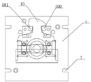
FIG. 4 is a schematic top view of the present invention.
In the figure, 1-an upper center plate, 2-a lower center plate, 3-a center positioning device, 301-a center positioning shaft, 302-a thrust ball bearing, 4-a pin protection positioning device, 401-a lower type pin protection positioning device, 402-an upper type pin protection positioning device, 403-a cylindrical head screw, 404-a processing hole, 5-a traction table positioning device, 501-an upper type traction flange positioning device, 502-a lower type traction flange positioning device, 6-an upper positioning device, 601-a support column, 602-a pressure plate, 603-a compression bolt, 604-a compression nut, 605-a compression sizing block, 606-a positioning sleeve, 607-a positioning pin, 7-a locking hole, 8-a quick-release locking bolt, 9-a processing device, 901-a cutter sleeve, 902-a cutter rod and 10-a coupler tongue body, 11-ruler.
Detailed Description
In order to make the objects, technical solutions and advantages of the embodiments of the present invention more apparent, the technical solutions of the embodiments of the present invention will be described clearly and completely with reference to the accompanying drawings of the embodiments of the present invention, and it is obvious that the described embodiments are some, but not all embodiments of the present invention. The components of embodiments of the present invention generally described and illustrated in the figures herein may be arranged and designed in a wide variety of different configurations.
Thus, the following detailed description of the embodiments of the present invention, presented in the figures, is not intended to limit the scope of the utility model, as claimed, but is merely representative of selected embodiments of the utility model. All other embodiments, which can be obtained by a person skilled in the art without any inventive step based on the embodiments of the present invention, are within the scope of the present invention.
In addition, the embodiments of the present invention and the features of the embodiments may be combined with each other without conflict.
It should be noted that: like reference numbers and letters refer to like items in the following figures, and thus, once an item is defined in one figure, it need not be further defined and explained in subsequent figures.
In the description of the present invention, it should be noted that the terms "center", "upper", "lower", "left", "right", "vertical", "horizontal", "inner", "outer", and the like indicate orientations or positional relationships based on the orientations or positional relationships shown in the drawings, or orientations or positional relationships that are conventionally placed when the products of the present invention are used, or orientations or positional relationships that are conventionally understood by those skilled in the art, and are used only for convenience of describing the present invention and simplifying the description, but do not indicate or imply that the device or element that is referred to must have a specific orientation, be constructed in a specific orientation, and be operated, and thus, should not be construed as limiting the present invention. Furthermore, the terms "first," "second," and the like are used merely to distinguish one description from another, and are not to be construed as indicating or implying relative importance.
In the description of the present invention, it should also be noted that, unless otherwise explicitly specified or limited, the terms "disposed," "mounted," "connected," and "connected" are to be construed broadly and may, for example, be fixedly connected, detachably connected, or integrally connected; can be mechanically or electrically connected; they may be connected directly or indirectly through intervening media, or they may be interconnected between two elements. The specific meanings of the above terms in the present invention can be understood in specific cases to those skilled in the art.
Referring to an embodiment shown in fig. 1-4, a coupler knuckle center lathe machining positioning device comprises an upper center plate 1 and a machining device 9, wherein a coupler knuckle body 10 is arranged on the upper center plate 1, the machining device 9 corresponds to a coupler knuckle pin hole of the coupler knuckle body 10, a lower center plate 2 is arranged on the bottom surface of the upper center plate 1, a center positioning device 3 is arranged on the upper center plate 1 and the lower center plate 2, a guard pin positioning device 4 is arranged on the upper center plate 1, a traction table positioning device 5 is arranged on the upper center plate 1, an upper positioning device 6 is arranged on the upper center plate 1 and the lower center plate 2, the center positioning device 3 is provided with a center positioning shaft 301 and a thrust ball bearing 302, the thrust ball bearing 302 is arranged inside the upper center plate 1 and the lower center plate 2, the center positioning shaft 301 penetrates through the upper center plate 1 and the lower center plate 2 and is connected with an inner ring of the thrust ball bearing 302, the guard pin positioning device 4 is provided with a lower guard pin positioning 401 and an upper guard pin positioning 402, a lower type guard pin positioning 401 is arranged on an upper core plate 1 through a cylindrical head screw 403, an upper type guard pin positioning 402 is arranged on the upper core plate 1 through the cylindrical head screw 403, machining holes 404 corresponding to a hook tongue pin hole on a hook tongue body 10 are respectively arranged on the lower type guard pin positioning 401 and the upper type guard pin positioning 402, a traction table positioning device 5 is provided with an upper type traction flange positioning 501 and a lower type traction flange positioning 502, the upper type traction flange positioning 501 is arranged on the upper core plate 1, the lower type traction flange positioning 502 is arranged on the upper core plate 1, an upper positioning device 6 is provided with a support column 601 and a positioning pin 607, the support column 601 is arranged on the upper core plate 1, the positioning pin 607 is arranged on the upper core plate 1 and the lower core plate 2 through a positioning sleeve 606, a pressing plate 602 is arranged on a pressing bolt 603, the bottom surface of the pressing plate 602 is interfered with the upper surface of the hook tongue body 10, a pressing nut 604 is arranged on the pressing bolt 603, and the bottom surface of the pressing plate 602 is interfered with the support column 601, a compression sizing block 605 is arranged between the pressure plate 602 and the coupler knuckle body 10, and is positioned by arranging a central positioning device 3 and an upper positioning device 6 which is designed to position the distance dimension from the center of a pin hole of the coupler knuckle body 10 to the vertical surface of the lock surface of the coupler knuckle body 10, so that the positioning deviation from the center of the pin hole of the coupler knuckle body 10 to the vertical surface of the lock surface of the coupler knuckle body 10 is prevented from causing the center of a pin hole of the coupler knuckle to directly generate equivalent deviation value transmission, and further the phenomena of assembly deviation, interference, uneven running stress and the like of the coupler knuckle are eliminated, the coupler knuckle traction table is firmer and not easy to crack, the service life of the coupler knuckle traction table is prolonged, the processing precision of the coupler knuckle body 10 and the loading application safety are improved, the processing device 9 is provided with a cutter sleeve 901, the cutter holder 902 is arranged on the cutter sleeve 901, the cutter sleeve 901 and the cutter holder correspond to the pin hole of the coupler knuckle body 10, the upper core plate 1 is provided with a locking hole 7, the locking hole 7 is provided with a quick-release locking bolt 8, the connecting strength between the upper core plate 1 and the lower core plate 2 is firmer by arranging the locking hole 7 and the quick-release locking bolt 8, the upper core plate 1 is provided with a ruler 11 for measuring the distance from the center of the pin hole to the vertical surface of the locking surface, and the distance L between the center of the pin hole and the vertical surface of the locking surface is conveniently measured by arranging the ruler 11.
The working process of the utility model is as follows: when the device is used, firstly, the coupler knuckle body 10 is preliminarily positioned through the pin protection positioning device 4 and the traction table positioning device 5 on the upper center plate 1, the machining hole 404 corresponds to a pin hole on the coupler knuckle body 10, the pressing sizing block 605 is placed on the coupler knuckle body 10, then the pressing plate 602 penetrates through the pressing bolt 603 to interfere with the upper surface of the coupler knuckle body 10 and simultaneously contacts with the pressing sizing block 605, the bottom surface of the pressing plate 602 interferes with the upper end of the supporting column 601, then the ruler 11 is started to be matched with the upper positioning device 6 to position the distance from the center of the pin hole of the coupler knuckle body 10 to the vertical surface of the lock face of the coupler knuckle, so that the positioning is more reasonable, and then the cutter bar 902 is started to be matched with the cutter sleeve 901 to machine the inside of the pin hole on the coupler knuckle body 10.
Although the present invention has been described in detail with reference to the foregoing embodiments, it will be apparent to those skilled in the art that various changes in the embodiments and/or modifications of the utility model can be made, and equivalents and modifications of some features of the utility model can be made without departing from the spirit and scope of the utility model.
Claims (8)
Priority Applications (1)
| Application Number | Priority Date | Filing Date | Title |
|---|---|---|---|
| CN202120200909.7U CN215393824U (en) | 2021-01-25 | 2021-01-25 | A kind of common lathe processing and positioning device for hook tongue |
Applications Claiming Priority (1)
| Application Number | Priority Date | Filing Date | Title |
|---|---|---|---|
| CN202120200909.7U CN215393824U (en) | 2021-01-25 | 2021-01-25 | A kind of common lathe processing and positioning device for hook tongue |
Publications (1)
| Publication Number | Publication Date |
|---|---|
| CN215393824U true CN215393824U (en) | 2022-01-04 |
Family
ID=79661931
Family Applications (1)
| Application Number | Title | Priority Date | Filing Date |
|---|---|---|---|
| CN202120200909.7U Expired - Fee Related CN215393824U (en) | 2021-01-25 | 2021-01-25 | A kind of common lathe processing and positioning device for hook tongue |
Country Status (1)
| Country | Link |
|---|---|
| CN (1) | CN215393824U (en) |
-
2021
- 2021-01-25 CN CN202120200909.7U patent/CN215393824U/en not_active Expired - Fee Related
Similar Documents
| Publication | Publication Date | Title |
|---|---|---|
| CN218612960U (en) | Bearing ring compresses tightly frock for drilling machine | |
| CN216245949U (en) | Quick detection device of trailer ball | |
| CN205209395U (en) | Car body strengthens utensil of examining of plate | |
| CN214351074U (en) | Clamp for machining oil cup opening of brake master cylinder | |
| CN213208896U (en) | Battery pack support deformation detection tool | |
| CN212095410U (en) | Fastening tool for workpiece machining | |
| CN213331589U (en) | Fan supporting cushion block | |
| CN214080373U (en) | Pull-down clamp | |
| CN216758909U (en) | Bearing end cover drilling and tapping tool | |
| CN112059612B (en) | Automobile steering knuckle shell clamp | |
| CN213106431U (en) | Automobile-used gearbox valve body adds clamping apparatus | |
| CN219685023U (en) | Sheet metal part polishing machine | |
| CN217358324U (en) | Automatic locking detection device for steering yoke | |
| CN214518797U (en) | Adjusting device for base of machine tool clothes closet | |
| CN219368581U (en) | Bottom shell position degree gauge | |
| CN221135029U (en) | Comprehensive clamp of brake caliper | |
| CN216263552U (en) | Auxiliary tool for machining outer circle of axle housing | |
| CN222758284U (en) | Thin-wall ring piece processing tool | |
| CN217290255U (en) | Flower-drum forging die convenient for processing tooth shape | |
| CN222784577U (en) | A kind of missing hole inspection tool | |
| CN206393243U (en) | Pattern block facade processing tool | |
| CN223454932U (en) | Stamping device for processing air compressor crankshafts | |
| CN218822272U (en) | Hub inner diameter measuring tool | |
| CN111730417A (en) | High-compression-resistance eccentric cover for machine tool and forming process thereof | |
| CN223389121U (en) | A skirt coaxiality detection device |
Legal Events
| Date | Code | Title | Description |
|---|---|---|---|
| GR01 | Patent grant | ||
| GR01 | Patent grant | ||
| CF01 | Termination of patent right due to non-payment of annual fee |
Granted publication date: 20220104 |
|
| CF01 | Termination of patent right due to non-payment of annual fee |