Aluminum pipe production die capable of achieving rapid cooling and demolding
Technical Field
The utility model relates to the field of production dies, in particular to an aluminum pipe production die capable of being cooled and demoulded quickly.
Background
The mould is various moulds and tools for obtaining required products by injection molding, blow molding, extrusion, die casting or forging forming, smelting, stamping and other methods in industrial production; in short, a mold is a tool used to make a shaped article, the tool being made up of various parts, different molds being made up of different parts.
The problem that the exhaust cooling speed is low in the casting process exists in the aluminum pipe production mold at the present stage; the problems that a finished aluminum pipe is difficult to demould, the die is integrally designed, and the maintenance cost is high exist. Accordingly, those skilled in the art have provided a rapid cooling and demolding aluminum pipe production mold which solves the problems set forth in the background art described above.
SUMMERY OF THE UTILITY MODEL
The utility model aims to provide an aluminum pipe production die capable of rapidly cooling and demolding, which aims to solve the problems in the background technology.
In order to achieve the purpose, the utility model provides the following technical scheme: an aluminum pipe production die capable of achieving rapid cooling and demolding comprises a lower die base, wherein an upper die base is installed on the top surface of the lower die base in a matched mode, a lower die frame plate is installed on the bottom surface of the lower die base in a threaded mode, an upper die frame plate is installed on the top surface of the upper die base in a threaded mode, side-mounted screws are installed on the two sides of the lower die base in a threaded mode, a pulling handle is welded on the left side wall surface of the lower die base, an outer side end plate is arranged on the right side end surface of the lower die base and the upper die base, a transverse casting hole is formed in the inner side of the outer side end plate, the left side of the transverse casting hole is communicated with the right side of a die core, an upper mounting screw is installed on the top surface of the upper die base in a threaded mode, a supplementary casting hole is formed in the top surface of the upper die base, an exhaust cooling device is fixedly installed on the right side end surfaces of the upper die base and the lower die base, the exhaust cooling device is communicated with the outer side of the die base through a connecting seat, and a disassembly combination plate is installed on the right side of the lower die base in a matched mode, the rapid cooling device has the advantages of rapid internal exhaust cooling, convenient demoulding and detachable mould.
Preferably, clamping seats are arranged on the front side end face and the rear side end face of the lower die seat, and frame plate handles are welded on the outer side of the lower die frame plate, so that the die is convenient to disassemble.
Preferably, the top surface of the upper die base is provided with a front end screw in a threaded manner, so that the upper die frame plate can be fixed.
Preferably, the bottom surface of the pulling handle is welded with the pulling base, so that the die is convenient to move.
Preferably, the top surface and the lower end surface of the detachable combined plate are provided with matching grains, so that the detachment and installation of the die can be realized.
Preferably, the inner side wall surface of the outer side end plate is provided with an exhaust groove, and the outer side wall surface of the outer side end plate is provided with an end plate screw in a threaded manner, so that the exhaust of the mold can be assisted.
Preferably, the mold core outside has been seted up inboard air vent, and the mold core right-hand member face installs the drawing of patterns mouth, the aluminium pipe mould body is installed to drawing of patterns mouth inside wall face, and aluminium pipe mould body bottom surface has seted up the drawing of patterns groove, the supplementary casting groove is installed on the upper left side top of aluminium pipe mould body, and the drawing of patterns of supplementary casting groove up end connection in supplementary casting hole bottom surface, the aluminium pipe of being convenient for.
Compared with the prior art, the utility model has the beneficial effects that:
(1) the utility model provides an aluminum pipe production mould of quick cooling demolding, parts such as aluminum pipe production mould installation exhaust cooling device and exhaust duct through giving quick cooling demolding, because the mould is at the casting process, the temperature is high, the fuse-element will replace the gas in the die cavity, if gas discharge is untimely, will cause the fuse-element to fill the difficulty, cause the injection volume not enough and can not be full of the die cavity, the finished product aluminum pipe that leads to in the die core gas pocket and hollow problem appear, therefore need carry out exhaust cooling from the mould is inside, inboard air vent is installed in the mold core outside to this product, let in exhaust cooling device through vent line, can, the exhaust duct has been seted up to the outside end plate simultaneously, assist the exhaust heat dissipation, realize the quick cooling of aluminum pipe.
(2) The aluminum pipe production die for rapid cooling demolding is provided with components such as a demolding opening, an aluminum pipe die body and the like, and the traditional die does not consider the large length-width ratio of the aluminum pipe, so that the aluminum pipe is easy to bend and deform due to large bending moment in the demolding process, and demolding grooves and demolding openings are formed in two sides of the aluminum pipe die body of the product, so that the aluminum pipe finished product can be conveniently and rapidly demolded; the equipment adopts a sectional assembly design, so that workers can maintain the die conveniently, and die parts are easy to maintain.
Drawings
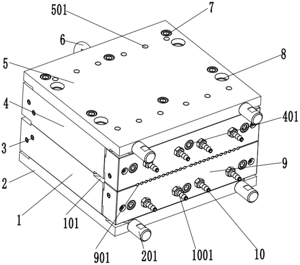
FIG. 1 is a schematic structural view of the present invention;
FIG. 2 is a partial schematic view showing the structure of the aluminum pipe producing mold according to the present invention;
FIG. 3 is a schematic sectional view of the structure of the die holder according to the present invention;
fig. 4 is a partial schematic view of the structure of the mold core of the present invention.
In the figure: 1. a lower die base; 101. clamping a seat; 2. a lower mold frame plate; 201. a frame plate handle; 3. side mounting screws; 4. an upper die base; 401. a front end screw; 5. an upper mold frame plate; 6. pulling the handle; 601. pulling the base; 7. mounting screws on the base; 8. hole repair casting; 9. disassembling the combined plate; 901. matching the lines; 10. an exhaust gas cooling device; 1001. a connecting seat; 11. an outer end plate; 1101. an exhaust groove; 1102. an end plate screw; 12. transverse casting holes; 13. a mold core; 1301. an inner vent hole; 1302. a demoulding port; 1303. an aluminum pipe die body; 1304. a demoulding groove; 1305. and (5) groove repair casting.
Detailed Description
The technical solutions in the embodiments of the present invention will be clearly and completely described below with reference to the drawings in the embodiments of the present invention, and it is obvious that the described embodiments are only a part of the embodiments of the present invention, and not all of the embodiments. All other embodiments, which can be derived by a person skilled in the art from the embodiments given herein without making any creative effort, shall fall within the protection scope of the present invention.
Referring to fig. 1-4, in the embodiment of the present invention, an aluminum pipe production mold for rapid cooling and mold stripping comprises a lower mold base 1, an upper mold base 4 is fittingly installed on the top surface of the lower mold base 1, a lower mold frame plate 2 is threadedly installed on the bottom surface of the lower mold base 1, an upper mold frame plate 5 is threadedly installed on the top surface of the upper mold base 4, side-installed screws 3 are threadedly installed on both sides of the lower mold base 1, a pull handle 6 is welded on the left side wall surface of the lower mold base 1, an outer side end plate 11 is installed on the right side end surfaces of the lower mold base 1 and the upper mold base 4, a transverse casting hole 12 is installed on the inner side of the outer side end plate 11, the left side of the transverse casting hole 12 is communicated with the right side of a mold core 13, an upper installation screw 7 is threadedly installed on the top surface of the upper mold base 4, a casting supplementing hole 8 is installed on the top surface of the upper mold base 4, and an exhaust cooling device 10 is fixedly installed on the right side end surfaces of the upper mold base 4 and the lower mold base 1, and exhaust cooling device 10 communicates in the mould seat outside through connecting seat 1001, and dismantlement compoboard 9 is installed in the cooperation of lower mould seat 1 right side, has inside quick exhaust cooling, makes things convenient for the drawing of patterns, mould detachable advantage.
The clamping seats 101 are arranged on the front side end face and the rear side end face of the lower die seat 1, and the frame plate handle 201 is welded on the outer side of the lower die frame plate 2, so that the die is convenient to disassemble; a front end screw 401 is arranged on the top surface of the upper die seat 4 in a threaded manner, so that the upper die frame plate 5 can be fixed; the bottom surface of the pulling handle 6 is welded with a pulling base 601, so that the die is convenient to move; matching lines 901 are arranged between the top surface and the lower end surface of the detachable combination board 9, so that the detachment and installation of the die can be realized; an exhaust groove 1101 is formed in the inner side wall surface of the outer side end plate 11, and an end plate screw 1102 is installed on the outer side wall surface of the outer side end plate 11 in a threaded mode and can assist in exhausting of the mold; an inner vent hole 1301 is formed in the outer side of the mold core 13, a demolding hole 1302 is formed in the right end face of the mold core 13, an aluminum pipe mold body 1303 is installed on the inner side wall face of the demolding hole 1302, a demolding groove 1304 is formed in the bottom face of the aluminum pipe mold body 1303, a casting supplementing groove 1305 is installed at the top end of the left upper side of the aluminum pipe mold body 1303, and the upper end face of the casting supplementing groove 1305 is connected to the bottom face of the casting supplementing hole 8, so that aluminum pipe demolding is facilitated.
The working principle is as follows: the main body of the aluminum pipe production die for fast cooling and demolding comprises a lower die seat 1, a lower die frame plate 2, a side screw 3, an upper die seat 4 and the like, and the device is different from common aluminum pipe dies in the market, and has the advantages of fast internal exhaust cooling, convenience in demolding and detachable die; because the temperature of the die is extremely high in the casting process, the melt replaces the gas in the cavity, if the gas is not discharged timely, the melt is difficult to fill, the injection quantity is insufficient, the cavity cannot be filled, and the problem of air holes and cavities of the finished aluminum tube in the die core 13 is caused, so that the exhaust cooling needs to be carried out from the inside of the die; because the traditional die does not consider the large length-width ratio of the aluminum tube, the aluminum tube is easy to bend and deform due to large bending moment in the demolding process, so that the demolding grooves 1304 and the demolding openings 1302 are formed in the two sides of the aluminum tube die body 1303 of the product, and the finished aluminum tube can be conveniently and rapidly demolded; the equipment adopts a sectional assembly design, so that workers can maintain the die conveniently, and die parts are easy to maintain.
Although embodiments of the present invention have been shown and described, it will be appreciated by those skilled in the art that changes, modifications, substitutions and alterations can be made in these embodiments without departing from the principles and spirit of the utility model, the scope of which is defined in the appended claims and their equivalents.