SUMMERY OF THE UTILITY MODEL
The utility model aims to provide an air-cooled power cabinet to improve the heat dissipation uniformity of a power module. Another object of the present invention is to provide a wind power converter including the above-mentioned wind cooling power cabinet.
In order to achieve the above object, the present invention provides an air-cooled power cabinet, comprising:
the cabinet is internally provided with a first cavity;
the module assembly is arranged in the first cavity and comprises a power module, the power module comprises a plurality of power modules, and the air inlet ends of the power modules are located at the same air inlet end of the power module.
Preferably, the plurality of power modules are sequentially arranged along a direction perpendicular to the airflow direction in the heat dissipation air duct in the first cavity.
Preferably, a second cavity which is independent of the first cavity is arranged in the cabinet, and the cabinet further comprises a reactor assembly which is arranged in the second cavity and comprises a reactor and a reactor cooling fan.
Preferably, the first cavity is located directly above the second cavity or the second cavity is located directly above the first cavity.
Preferably, the second cavity is located at the bottom of the cabinet, the air inlet of the second cavity is located at the bottom wall of the cabinet, and the air outlet of the second cavity is located at the side wall of the cabinet.
Preferably, the air outlet of the second cavity is located on a back plate of the cabinet, and the air outlet of the second cavity is provided with a breathable dust screen.
Preferably, the air inlet of the second cavity is provided with a breathable dustproof net.
Preferably, the reactor is located upstream of the reactor radiator fan in the direction of gas flow in the second chamber.
Preferably, the reactor assembly further comprises an air duct partition plate sleeved on the periphery of the reactor, and an air duct is formed between the air duct partition plate and a coil of the reactor.
Preferably, the top end of the air duct partition plate is located in the middle of the height of the reactor assembly, and the plate surface of the air duct partition plate is perpendicular to the central axis of the reactor assembly.
Preferably, the number of the reactors is multiple, each reactor comprises a coil and a support arranged between coils of adjacent coils, and an air channel in the same direction as the air flow direction of the second cavity is formed between two adjacent layers of the coils.
Preferably, a third cavity communicated with the first cavity is arranged in the cabinet, the cabinet further comprises a peripheral heating accessory arranged in the third cavity, the third cavity and the first cavity share an air inlet, and an air outlet of the third cavity is an opening communicated with the first cavity.
Preferably, the third cavity is located right above the first cavity, and the third cavity is located at the top end of the cabinet.
Preferably, the peripheral heating accessory comprises a filter capacitor assembly and/or a crowbar control unit and/or a crowbar resistor.
Preferably, the air outlet of the first cavity and the air inlet of the first cavity are respectively located on the side wall of the cabinet, which is arranged back to back.
Preferably, the extending direction of the heat sink fins of the power module is the air flow direction in the module assembly.
Preferably, the module assembly further comprises a dc bus disposed on the windward side of the power module, and the central symmetry line of the dc bus is coplanar with the central symmetry plane of the power module.
Preferably, first cavity includes module installation cavity, module collection wind chamber and the fan installation cavity that sets gradually along the gas flow direction, the power module is installed the module installation cavity, the module subassembly is including setting up module radiator fan in the fan installation cavity.
Preferably, the air inlet end of the module air collecting cavity is in sealed connection with the edge of the air outlet end of the module mounting cavity, and the air outlet end of the module air collecting cavity is in sealed connection with the edge of the air inlet end of the fan mounting cavity.
Preferably, the air inlets of the air collecting cavity are multiple, the air inlets of the air collecting cavity correspond to the power modules one by one, and the air inlets of the air collecting cavity are attached to the power module radiator of the power module.
A wind power converter comprises an air-cooled power cabinet, wherein the air-cooled power cabinet is any one of the air-cooled power cabinets.
In the technical scheme, the air-cooled power cabinet provided by the utility model comprises a cabinet and a module assembly, wherein a first cavity is arranged in the cabinet; the module assembly is arranged in the first cavity and comprises a power module and a module cooling fan, the power module comprises a plurality of power modules, and the air inlet ends of the power modules are located at the same air inlet end of the power module.
According to the air-cooled power cabinet, the air inlet ends of the power modules are located at the same air inlet end of the power module, namely the air inlet temperatures of the power modules are the same, so that the heat dissipation effects of the power modules tend to be uniform, and the heat dissipation uniformity of the power modules is improved.
Detailed Description
The core of the utility model is to provide the air-cooled power cabinet to improve the heat dissipation uniformity of the power module. The other core of the utility model is to provide a wind power converter comprising the wind cooling power cabinet.
In order to make the technical solutions of the present invention better understood by those skilled in the art, the present invention will be further described in detail with reference to the accompanying drawings and embodiments.
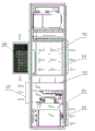
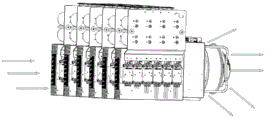
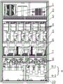
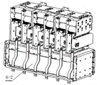
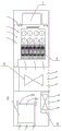
Please refer to fig. 4 to fig. 11.
In a specific implementation manner, the air-cooled power cabinet provided in the specific embodiment of the present invention includes a cabinet 10 and a module assembly, wherein a first cavity is disposed in the cabinet 10; the module assembly is arranged in the first cavity and comprises a power module 4, the power module 4 comprises a plurality of power modules 4-2, and air inlet ends of the power modules 4-2 are located at the same air inlet end of the power module 4. Preferably, the power module 4 includes the module radiator fan 6 disposed in the first cavity, wherein the installation number of the module radiator fan 6 is based on the actual requirement, and the present application is not specifically limited, and preferably, all the module radiator fans 6 are disposed along the direction of the rotation axis of the fan blade perpendicular to the module radiator fan 6. Specifically, the module heat dissipation fan 6 may be located at an air inlet of the first cavity or an air outlet of the first cavity, and when the module heat dissipation fan 6 is located at the air outlet of the first cavity, the module heat dissipation fan air outlet 10-3 of the module heat dissipation fan 6 is the air outlet of the first cavity.
Preferably, the plurality of power modules 4-2 are arranged in sequence along a direction perpendicular to the airflow direction in the heat dissipation air duct in the first cavity. Specifically, all the power modules 4-2 may be arranged in sequence along a direction perpendicular to the airflow direction in the heat dissipation air duct in the first cavity.
As can be seen from the above description, in the air-cooled power cabinet provided in the embodiment of the present application, since the air inlet ends of the multiple power modules 4-2 are located at the same air inlet end of the power module 4, that is, the air inlet temperatures of the multiple power modules 4-2 are the same, the heat dissipation effects of the multiple power modules 4-2 tend to be uniform, and further, the heat dissipation uniformity of the power modules 4-2 is improved.
Because the module radiator fan 6 is arranged in the cabinet 10, the outside of the cabinet 10 is not protruded, the size of the maximum appearance thickness direction of the cabinet 10 is reduced, thereby indirectly reducing the packaging and transportation cost, and the appearance of the cabinet 10 is more beautiful.
In a specific embodiment, a second cavity which is independent from the first cavity is arranged in the cabinet 10, and the reactor assembly 9 is arranged in the second cavity, and the reactor assembly 9 includes a reactor and a reactor cooling fan 8. Specifically, the fan partition plate 7 is used as a boundary between the first cavity and the second cavity, and the fan partition plate 7 isolates air flow between the first cavity and the second cavity, so that the power module 4 and the reactor assembly 9 form an independent heat dissipation air duct.
Wherein the reactor assembly 9 comprises a machine side reactor 9-1 and a grid side reactor 9-2. Specifically, the reactor cooling fan 8 may be located downstream of the reactor assembly 9, and specifically may be located at an upper rear position of the second cavity.
Because the heat dissipation air duct of the power module 4 is completely independent of the heat dissipation air duct of the reactor component 9, the two components with the largest heat generation in the cabinet 10 can ensure that the respective heat dissipation air ducts do not influence each other, reduce the internal environment temperature of the cabinet 10 to the maximum extent, and further prolong the service life of devices.
In specific implementation, the first cavity is located right above the second cavity, or the second cavity is located right above the first cavity. Or the first cavity and the second cavity can be horizontally and transversely arranged
In a specific embodiment, the second cavity is located at the bottom of the cabinet 10, the air inlet of the second cavity is located at the bottom wall of the cabinet 10, and the air outlet of the second cavity is located at the side wall of the cabinet 10. Specifically, a cabinet bottom plate 10-1 of the cabinet 10 is located at a position corresponding to the bottom of the reactor assembly 9, and preferably, an air inlet of the second cavity is provided with a breathable dust screen. Specifically, the air inlet is provided with structural grid holes as an air-permeable dustproof net, and the net separation holes are used as the air inlet of the second cavity.
Specifically, the air outlet of the second cavity is located on the back plate of the cabinet 10. Preferably, the air outlet of the second cavity is provided with a breathable dustproof net. The back board of the cabinet 10 is located at a position corresponding to the module cooling fan 6 and the reactor cooling fan 8, and has structural grid holes as a breathable dustproof net. The air current in the second cavity passes through an air inlet at the bottom of the cabinet 10, then enters the reactor assembly 9, takes away heat, passes through the reactor cooling fan 8, passes through the backboard grid holes, and is discharged out of the cabinet 10.
Specifically, the air outlet of the first cavity and the air outlet of the second cavity are both located on the back plate of the cabinet 10.
Specifically, in particular use, the reactor is located upstream of the reactor radiator fan 8 in the direction of gas flow in the second chamber. The reactor cooling fan 8 may be located at an air outlet of the second cavity, that is, the reactor cooling fan air outlet 10-4 is an air outlet of the second cavity.
In a specific embodiment, the reactor assembly 9 further includes an air duct partition plate sleeved on the periphery of the reactor, and an air duct is formed between the air duct partition plate and the reactor coil. The top end of the air duct partition plate is located in the middle of the height of the reactor assembly 9, namely the air duct partition plate is optimally arranged at the midpoint of the reactor in the height direction and is perpendicular to the central axis of the reactor assembly 9.
In a specific implementation mode, the reactor is multiple, the reactor comprises coils and a support arranged between coils of adjacent coils, and an air channel in the same direction as the air flow direction of the second cavity is formed between two adjacent layers of coils. Specifically, the coil may be formed by winding aluminum foil, and the brackets are directly provided on different layers of aluminum foil, so that a ventilation duct penetrating up and down is formed inside the reactor component 9.
In order to improve the overall heat dissipation efficiency of the heating device in the air-cooled power cabinet, preferably, a third cavity communicated with the first cavity is arranged in the cabinet 10, and the air-cooled power cabinet further comprises a peripheral heating accessory 1 arranged in the third cavity, specifically, the peripheral heating accessory 1 comprises a filter capacitor assembly and/or a crowbar control unit and/or a crowbar resistor and other low-heating-value electric devices.
The third cavity and the first cavity share the air inlet, and the air outlet of the third cavity is an opening communicated with the first cavity. Specifically, the second cavity is located below the first cavity, and the third cavity is located above the first cavity. The third cavity and the first cavity can use the first cavity mounting plate 2 as a boundary line, wherein the first cavity mounting plate 2 is provided with a ventilation mesh, so that air can enter the first cavity from the third cavity through the mesh, and then some cold air can be ensured to flow through the peripheral heating fitting 1, and the peripheral heating fitting 1 is cooled.
Specifically, the third chamber is located at the top of the cabinet 10. Because the module cooling fan 6 is arranged in the cabinet 10, the front maintenance can be carried out, the maintenance efficiency is improved, and the maintenance space required by the air cooling power cabinet is reduced.
The air outlet of the first cavity and the air inlet of the first cavity at the bottom end are respectively located on the side wall of the cabinet 10, which is arranged back to back. The air inlet of the first cavity is provided with a shutter 10-2, specifically, the shutter 10-2 is arranged on a front door plate of the cabinet 10, and the center height of the shutter is positioned above the power module 4; the shutter 10-2 is a heat dissipation air inlet of the power module 4.
In one embodiment, the heat sink fins of the power module heat sink 4-1 extend in the direction of the module assembly airflow. Specifically, two heat sink fins are arranged in parallel.
Specifically, the module assembly further comprises a direct current bus 3 arranged on the windward side of the power module 4, and the central symmetry line of the direct current bus 3 is coplanar with the center of the power module 4. Specifically, the dc bus 3 is located above the power module 4, and the installation position of the dc bus is symmetrical to the power module 4, so that the ripple of the power module 4 is effectively reduced.
On the basis of above-mentioned each scheme, preferably, first cavity includes module installation cavity, module collection wind chamber 5 and the fan installation cavity that sets gradually along the gas flow direction, and power module 4 installs in the module installation cavity, and module radiator fan 8 installs in the fan installation cavity. Specifically, the front of the mounting area of the module radiator fan 6 is sealed by a front sealing plate 6-2, the mounting area of the module radiator fan 6 is sealed by a side sealing plate 6-1, and only the rear end can ventilate, so that the air duct is ensured to flow to a mesh partition hole 10-3 in an air outlet of the module radiator fan 6 of the rear door plate in the mechanism 10.
For the convenience of smooth air flow, it is preferred that the air inlet end of module collection wind chamber 5 and the air-out end edge of module installation cavity are sealed and linked up, and the air-out end of module collection wind chamber 5 and the air-in end edge of fan installation cavity are sealed and linked up.
Specifically, the module air collecting cavity 5 can be fixed on the vertical beam of the cabinet 10 by two ends, and the module heat dissipation fan 6 is positioned at the lower end of the module air collecting cavity 5; the power module 4 is installed on the upper end face of the module air collecting cavity 5, the direct current bus 3 is connected to a direct current side leading-out terminal on the power module 4, and the direct current bus 3 and the power module 4 are in a completely symmetrical position.
Preferably, the air inlets of the air collecting cavity are multiple, the air inlets of the air collecting cavity correspond to the power modules 4-2 one by one, and the air inlets of the air collecting cavity are attached to the power module radiators 4-1 of the power module 4. When six ventilation openings are formed in the upper end face of the module air collecting cavity 5, one single power module 4-2 corresponds to one ventilation opening, and the ventilation openings are attached to the power module radiator 4-1.
For example, the power module 4 includes six single-phase power modules 4-2, which are arranged in two ways: one is that: the power supply is divided into a left group and a right group, each group comprises three different phases of a three-phase power supply, the left group is three grid-side single-phase power modules, and the right group is three machine-side single-phase power modules. The other is the cross distribution of the machine net side. Both schemes can be realized and selected according to practical application. The arrangement sequence of the machine net side can be A-B-C-U-V-W, or the cross arrangement of the machine net side A-U-B-V-C-W is based on the actual requirement.
Most of the cold air flow directly enters the first cavity through the air inlet of the first cavity, and a small part of the cold air flow passes through the peripheral heating accessory 1 of the third cavity. Then the heat of the power module 4 is taken away by the power module radiator 4-1, enters the module air collecting cavity 5, flows through the plate grid holes of the rear door by the module radiating fan 6, and is discharged out of the cabinet 10. The louver 10-2 of the air inlet of the first cavity can be replaced by other ventilation structures, and the actual standard is to be met.
The working process is further described with reference to fig. 10, when the device is operated, the module heat dissipation fan 6 rotates to form a negative pressure, the cold air flow enters from the louver 10-2 of the front panel, passes through the power module 4, enters the power module heat sink 4-1 of the power module 4, meanwhile, a part of the cold air flow passes through the third cavity, takes away the heat of the peripheral heat generating accessory 1, then enters the first cavity through the first cavity mounting plate 2, then flows through the power module heat sink 4-1, takes away the whole heat, and the cold air flow is changed into hot air flow. Because the power module radiator 4-1 is tightly attached to the module air-collecting cavity 5, hot air completely enters the module air-collecting cavity 5, and then is thrown out of the cabinet 10 through the module heat-dissipating fan 6 and the module heat-dissipating fan air outlet 10-3 at the back of the cabinet 10.
It can be seen that the air inlet direction of the power module 4 is vertical to the arrangement of the power modules 4-2, the air inlet temperature of each power module 4-2 is the same, the fin paths of the power module radiators 4-1 flowing through the fin paths are the same, the heat dissipation effect of each power module 4-2 is guaranteed to be the same, and the structural form of the air duct can achieve the effect of reducing the temperature rise of the power module 4-2 by using the power module radiators 4-1 in the common process.
The application provides an air-cooled power cabinet, overall structure is simple, improves air-cooled power cabinet maintainability, reduces 10 maximum dimensions of rack, reduces this packing cost of transportation, improves the power cabinet outward appearance. Meanwhile, the process technology cost of the power module radiator 4-1 is reduced, and further the system cost of the air cooling power cabinet is reduced. The heat dissipation structure is particularly suitable for the power module 4 with the multiple power modules 4-2 connected in parallel, so that the heat dissipation efficiency of each power module 4-2 on the power module 4 is the same, the heat dissipation efficiency is the highest, and the process technology cost of the power module heat sink 4-1 is reduced.
The application provides a wind power converter, including the forced air cooling power cabinet, wherein, the forced air cooling power cabinet is any kind of forced air cooling power cabinet of above-mentioned. The foregoing describes a specific structure of an air-cooled power cabinet, and the present application includes the above-mentioned air-cooled power cabinet, which also has the above-mentioned technical effects.
The embodiments in the present description are described in a progressive manner, each embodiment focuses on differences from other embodiments, and the same and similar parts among the embodiments are referred to each other.
The previous description of the disclosed embodiments is provided to enable any person skilled in the art to make or use the present invention. Various modifications to these embodiments will be readily apparent to those skilled in the art, and the generic principles defined herein may be applied to other embodiments without departing from the spirit or scope of the utility model. Thus, the present invention is not intended to be limited to the embodiments shown herein but is to be accorded the widest scope consistent with the principles and novel features disclosed herein.