CN215378216U - Agricultural planting ground electric power engineering is with special high-voltage substation cabinet - Google Patents
Agricultural planting ground electric power engineering is with special high-voltage substation cabinet Download PDFInfo
- Publication number
- CN215378216U CN215378216U CN202121859715.4U CN202121859715U CN215378216U CN 215378216 U CN215378216 U CN 215378216U CN 202121859715 U CN202121859715 U CN 202121859715U CN 215378216 U CN215378216 U CN 215378216U
- Authority
- CN
- China
- Prior art keywords
- dust removal
- main body
- cabinet main
- removal box
- power transformation
- Prior art date
- Legal status (The legal status is an assumption and is not a legal conclusion. Google has not performed a legal analysis and makes no representation as to the accuracy of the status listed.)
- Expired - Fee Related
Links
- 239000000428 dust Substances 0.000 claims abstract description 58
- 230000009466 transformation Effects 0.000 claims abstract description 29
- 230000017525 heat dissipation Effects 0.000 claims abstract description 25
- OKTJSMMVPCPJKN-UHFFFAOYSA-N Carbon Chemical compound [C] OKTJSMMVPCPJKN-UHFFFAOYSA-N 0.000 claims description 20
- 238000009434 installation Methods 0.000 claims description 6
- 238000009423 ventilation Methods 0.000 claims description 5
- 238000005192 partition Methods 0.000 claims description 4
- 238000000034 method Methods 0.000 claims description 3
- 210000005056 cell body Anatomy 0.000 claims description 2
- 238000009825 accumulation Methods 0.000 description 2
- 230000008901 benefit Effects 0.000 description 2
- 230000005540 biological transmission Effects 0.000 description 2
- 238000009313 farming Methods 0.000 description 2
- 238000004519 manufacturing process Methods 0.000 description 2
- 238000006243 chemical reaction Methods 0.000 description 1
- 238000010276 construction Methods 0.000 description 1
- 238000010586 diagram Methods 0.000 description 1
- 230000000694 effects Effects 0.000 description 1
- 238000005516 engineering process Methods 0.000 description 1
- 230000007246 mechanism Effects 0.000 description 1
- 230000004048 modification Effects 0.000 description 1
- 238000012986 modification Methods 0.000 description 1
- 238000010248 power generation Methods 0.000 description 1
- 230000008569 process Effects 0.000 description 1
- 238000000638 solvent extraction Methods 0.000 description 1
Images


Landscapes
- Patch Boards (AREA)
Abstract
The utility model discloses a special high-voltage power transformation cabinet for electric power engineering in agricultural planting areas, which comprises a base with a top fixedly provided with a power transformation cabinet main body and a heat dissipation assembly detachably arranged on one side of the power transformation cabinet main body, wherein two first air pumps are fixedly arranged above one side of the power transformation cabinet main body provided with the heat dissipation assembly through pipelines, the heat dissipation assembly comprises a rectangular plate with one side provided with a dust filter screen in the middle and a dust removal box fixedly arranged on one side of the rectangular plate, two second air pumps communicated with the interior of the dust removal box through pipelines are symmetrically and fixedly arranged on the top of one side of the dust removal box away from the power transformation cabinet main body, and a rectangular groove communicated with the interior of the dust removal box and used for fixedly installing an air permeable screen is arranged at the bottom of one side of the dust removal box away from the power transformation cabinet main body, the practicability is strong.
Description
Technical Field
The utility model belongs to the technical field of high-voltage power transformation cabinets, and particularly relates to a special high-voltage power transformation cabinet for power engineering of an agricultural planting field.
Background
The high-voltage transformer cabinet is an electrical appliance product which is used for power generation, power transmission, power distribution, electric energy conversion and consumption of an electric power system and plays roles of on-off, control or protection and the like, and the voltage level is 3.6 kV-550 kV, and mainly comprises a high-voltage circuit breaker, a high-voltage isolating switch, a grounding switch, a high-voltage load switch, a high-voltage automatic reclosing and sectioning device, a high-voltage operating mechanism, a high-voltage explosion-proof power distribution device, a high-voltage switch cabinet and the like. The high-voltage switch manufacturing industry is an important component of the power transmission and transformation equipment manufacturing industry and plays a very important role in the whole power industry.
Present high-voltage transformer cabinet, its inside device can produce the heat at the in-process of operation, and under long-time work, inside heat is piled up and is difficult to initiative discharge, only is difficult to carry out quick heat dissipation through the radiating groove that transformer cabinet surface was seted up, influences the normal operating of the inside device of transformer cabinet.
SUMMERY OF THE UTILITY MODEL
The utility model aims to provide a special high-voltage transformer cabinet for an electric power project of an agricultural planting field, which aims to solve the problems that heat accumulation generated in the operation process of internal devices of the transformer cabinet in the background technology is difficult to actively discharge and rapid heat dissipation cannot be performed.
In order to achieve the purpose, the utility model provides the following technical scheme: a special high-voltage power transformation cabinet for electric power engineering of an agricultural planting field comprises a base with a power transformation cabinet main body fixedly arranged at the top and a heat dissipation assembly detachably arranged on one side of the power transformation cabinet main body;
the dust filter comprises a transformer cabinet main body, a dust filter screen, a dust removal box and a dust collection box, wherein two air pumps I are fixedly arranged above one side of the transformer cabinet main body, which is provided with a heat dissipation assembly, through pipelines, and a through groove is formed in the abutting position of the transformer cabinet main body and the heat dissipation assembly;
the top of one side of the dedusting box far away from the transformer cabinet main body is symmetrically and fixedly provided with two air pumps II communicated with the inside of the dedusting box through pipelines, and the bottom of one side of the dedusting box far away from the transformer cabinet main body is provided with a rectangular groove communicated with the inside of the dedusting box and used for fixedly installing a ventilation net.
Preferably, the top and the bottom of one side that the transformer cabinet main part was kept away from to the rectangular plate are equidistant to be provided with a plurality of connecting pieces that are used for dismantling radiator unit and transformer cabinet main part and be connected.
Preferably, a partition plate for partitioning the inner part of the dust removal box into two chambers is constructed in the dust removal box, an activated carbon layer is fixedly arranged in the two chambers in the middle, and filter screens are fixedly arranged on two sides of the activated carbon layer in the two chambers.
Preferably, the cell body that supplies rectangle framework demountable installation is seted up between two parties to one side of dust removal box, the equal distance in one side top and the bottom that the dust removal box was kept away from to the rectangle framework is provided with a plurality of installed parts that are used for carrying out the demountable connection with rectangle framework and dust removal box, and fixed mounting has the dust screen in the rectangle framework.
Preferably, the both sides of base are all constructed centrally and are extended the board, the equidistance is provided with a plurality of mountings that are used for carrying out fixed mounting to the base in the extended plate, and extended plate up end symmetric construction has two to support the rib.
Preferably, one side of the base is provided with a cabinet door in a hinged mode through a hinge, and two buckling grooves for facilitating opening of the cabinet door are symmetrically formed in the cabinet door.
The utility model has the technical effects and advantages that: this farming land is special high-voltage power transformation cabinet for electric power engineering, benefit from the setting of radiator unit and air pump one, through starting air pump one, can make the inside atmospheric pressure of transformer cabinet main part reduce, thereby make external cold air enter into the dust removal box through ventilative net, and enter into in the transformer cabinet main part through the dirt filtrating net, start air pump two simultaneously, make the inside atmospheric pressure of dust removal box reduce, hot-air in the transformer cabinet main part enters into the dust removal box through the dirt filtrating net, and discharge thereupon, realize the circulation of cold and hot air, realize the initiative heat dissipation, avoid thermal pile up the normal operating that influences the inside device of transformer cabinet main part.
Drawings
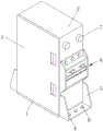
FIG. 1 is a schematic structural view of the present invention;
FIG. 2 is a schematic structural diagram of a heat dissipation assembly according to the present invention;
fig. 3 is a cross-sectional view taken at a-a of fig. 2 in accordance with the present invention.
In the figure: 1. a base; 2. a power transformation cabinet main body; 3. a cabinet door; 4. an extension plate; 5. a support rib; 6. a fixing member; 7. a first air pump; 8. a heat dissipating component; 801. a rectangular plate; 802. a connecting member; 803. a dust removal box; 804. a second air pump; 805. a rectangular frame body; 806. a dust screen; 807. a breathable net; 808. a filter screen; 809. an activated carbon layer; 810. a partition plate; 811. and (4) a dust filter screen.
Detailed Description
The technical solutions in the embodiments of the present invention will be clearly and completely described below with reference to the drawings in the embodiments of the present invention, and it is obvious that the described embodiments are only a part of the embodiments of the present invention, and not all of the embodiments. All other embodiments, which can be derived by a person skilled in the art from the embodiments given herein without making any creative effort, shall fall within the protection scope of the present invention.
In order to realize active heat dissipation and avoid heat accumulation from influencing the normal operation of devices in the transformer cabinet, as shown in fig. 1-3, the special high-voltage transformer cabinet for the power engineering of the agricultural planting field comprises a base 1 with a transformer cabinet main body 2 fixedly mounted at the top and a heat dissipation assembly 8 detachably arranged on one side of the transformer cabinet main body 2, two air pumps I7 are fixedly mounted above one side of the transformer cabinet main body 2 provided with the heat dissipation assembly 8 through pipelines, and a through groove is formed in the abutting position of the transformer cabinet main body 2 and the heat dissipation assembly 8;
as shown in fig. 2 and 3, the heat dissipation assembly 8 includes a rectangular plate 801 with one side fixedly installed with a dust filter net 811 in the middle and a dust removal box 803 fixedly installed on one side of the rectangular plate 801, two air pumps 804 connected to the inside of the dust removal box 803 through pipes are symmetrically and fixedly installed on the top of one side of the dust removal box 803 away from the transformer cabinet main body 2, and a rectangular groove connected to the inside of the dust removal box 803 and used for fixedly installing a ventilation net 807 is opened on the bottom of one side of the dust removal box 803 away from the transformer cabinet main body 2, so that, thanks to the arrangement of the heat dissipation assembly 8 and the air pump one 7, the air pressure inside the transformer cabinet main body 2 can be reduced by starting the air pump one 7, thereby the external cold air enters the dust removal box 803 through the ventilation net 811 and enters the transformer cabinet main body 2 through the dust filter net 811, and simultaneously the air pumps 804 are started to reduce the air pressure inside the dust removal box 803, and the hot air inside the transformer cabinet main body 2 enters the dust removal box 803 through the dust filter net 811, and then discharge, realize the circulation of cold and hot air, realize initiatively dispelling the heat, avoid thermal pile up the normal operating that influences the inside device of transformer cabinet main part 2.
In order to achieve active heat dissipation and reduce dust entering, as shown in fig. 1-3, a plurality of connecting members 802 for detachably connecting the heat dissipation assembly 8 and the substation main body 2 are arranged at equal distances at the top and bottom of one side of the rectangular plate 801 away from the substation main body 2 (in specific implementation, the connecting members 802 may be selected but are not limited to be selected with bolts), a groove body for detachably mounting the rectangular frame 805 is formed in the middle of one side of the dust removal box 803, a plurality of mounting members for detachably connecting the rectangular frame 805 and the dust removal box 803 are arranged at equal distances at the top and bottom of one side of the rectangular frame 805 away from the dust removal box 803 (in specific implementation, the mounting members may be selected but are not limited to be selected with bolts), and a dust screen 806 is fixedly mounted in the rectangular frame 805;
as shown in fig. 3, a partition 810 for dividing the interior of the dust removal box 803 into two chambers is configured in the dust removal box 803, an activated carbon layer 809 is fixedly disposed in each of the two chambers, and filter screens 808 are fixedly mounted on both sides of the activated carbon layer 809 in each of the two chambers (in specific implementation, cold air entering the dust removal box 803 is filtered and decontaminated through the filter screens 808 and the activated carbon layer 809 to avoid bringing dust into the dust removal box, and enters the transformer cabinet main body 2 through the dust filter screen 811).
In order to facilitate the fixed installation of the power transformation cabinet, as shown in fig. 1-3, two sides of the base 1 are both provided with an extension plate 4 in the middle, a plurality of fixing members 6 (during specific implementation, the fixing members 6 can be selected and used without limitation to select bolts) for the fixed installation of the base 1 are arranged in the extension plate 4 at equal intervals, two support ribs 5 are symmetrically arranged on the upper end face of the extension plate 4, one side of the base 1 is provided with a cabinet door 3 through hinges, and two fastening grooves for facilitating the opening of the cabinet door 3 are symmetrically arranged in the cabinet door 3.
The working principle is as follows: when the special high-voltage power transformation cabinet for the electric power engineering of the agricultural planting field is used, the base 1 is placed at the installation position, the fixing of the base 1 and the power transformation cabinet main body 2 is realized by screwing the fixing piece 6 into the pre-drilled installation hole, the air pressure in the power transformation cabinet main body 2 can be reduced by starting the air pump I7, so that outside cold air enters the dust removal box 803 through the ventilation net 807, the cold air entering the dust removal box 803 is filtered and decontaminated through the filter net 808 and the activated carbon layer 809 to avoid bringing dust into the power transformation cabinet main body 2, the air pump II 804 is started to reduce the air pressure in the dust removal box 803, hot air in the power transformation cabinet main body 2 enters the dust removal box 803 through the dust filter net 811, and is discharged to the outside after being filtered by the filter net 808 and the activated carbon layer 809 to realize the circulation of the cold air, this special high-voltage power transformation cabinet for farming ground electric power engineering, it is rational in infrastructure, be convenient for realize initiative heat dissipation, avoid the heat to pile up the normal operating that influences the inside device of power transformation cabinet, the practicality is strong.
Finally, it should be noted that: although the present invention has been described in detail with reference to the foregoing embodiments, it will be apparent to those skilled in the art that modifications may be made to the embodiments or portions thereof without departing from the spirit and scope of the utility model.
Claims (6)
1. A special high-voltage power transformation cabinet for an electric power project of an agricultural planting field comprises a base (1) and a heat dissipation assembly (8), wherein the top of the base (1) is fixedly provided with a power transformation cabinet main body (2), and the heat dissipation assembly (8) is detachably arranged on one side of the power transformation cabinet main body (2);
the method is characterized in that: two air pumps I (7) are fixedly mounted above one side, provided with a heat dissipation assembly (8), of the transformer cabinet main body (2) through a pipeline, a through groove is formed in the abutting position of the transformer cabinet main body (2) and the heat dissipation assembly (8), and the heat dissipation assembly (8) comprises a rectangular plate (801) and a dust removal box (803), wherein a dust filter screen (811) is fixedly mounted in the middle of one side of the rectangular plate (801);
the top of one side of the dedusting box (803) far away from the transformer cabinet main body (2) is symmetrically and fixedly provided with two air pumps (804) communicated with the interior of the dedusting box (803) through pipelines, and the bottom of one side of the dedusting box (803) far away from the transformer cabinet main body (2) is provided with a rectangular groove communicated with the interior of the dedusting box (803) and fixedly provided with a ventilation net (807).
2. The special high-voltage power transformation cabinet for the electric power engineering of the agricultural planting field according to claim 1, characterized in that: the top and the bottom of one side of rectangular plate (801) far away from transformer cabinet main part (2) are equidistantly provided with a plurality of connecting pieces (802) used for detachably connecting heat dissipation assembly (8) with transformer cabinet main part (2).
3. The special high-voltage power transformation cabinet for the electric power engineering of the agricultural planting field according to claim 2, characterized in that: the dust removal box (803) is internally provided with a partition plate (810) which is used for separating the interior of the dust removal box (803) into two cavities, the two cavities are internally provided with an activated carbon layer (809) in a fixed mode, and filter screens (808) are fixedly arranged on two sides of the activated carbon layer (809) in the two cavities.
4. The special high-voltage transformer cabinet for the electric power engineering of the agricultural planting field according to claim 3, characterized in that: one side of dust removal box (803) is seted up the cell body that supplies rectangle framework (805) demountable installation between two parties, one side top and the bottom equidistance that dust removal box (803) was kept away from in rectangle framework (805) are provided with a plurality of installed parts that are used for carrying out the dismantlement with rectangle framework (805) and dust removal box (803) and be connected, and fixed mounting has dust screen (806) in rectangle framework (805).
5. The special high-voltage power transformation cabinet for the electric power engineering of the agricultural planting field according to claim 1, characterized in that: the both sides of base (1) are all constructed extension board (4) between two parties, the equidistance is provided with a plurality of mounting (6) that are used for carrying out fixed mounting to base (1) in extension board (4), and extension board (4) up end symmetry constructs two and supports rib (5).
6. The special high-voltage power transformation cabinet for the electric power engineering of the agricultural planting field according to claim 1, characterized in that: one side of the base (1) is provided with a cabinet door (3) through hinges, and two fastening grooves for opening the cabinet door (3) are symmetrically formed in the cabinet door (3).
Priority Applications (1)
| Application Number | Priority Date | Filing Date | Title |
|---|---|---|---|
| CN202121859715.4U CN215378216U (en) | 2021-08-10 | 2021-08-10 | Agricultural planting ground electric power engineering is with special high-voltage substation cabinet |
Applications Claiming Priority (1)
| Application Number | Priority Date | Filing Date | Title |
|---|---|---|---|
| CN202121859715.4U CN215378216U (en) | 2021-08-10 | 2021-08-10 | Agricultural planting ground electric power engineering is with special high-voltage substation cabinet |
Publications (1)
| Publication Number | Publication Date |
|---|---|
| CN215378216U true CN215378216U (en) | 2021-12-31 |
Family
ID=79617456
Family Applications (1)
| Application Number | Title | Priority Date | Filing Date |
|---|---|---|---|
| CN202121859715.4U Expired - Fee Related CN215378216U (en) | 2021-08-10 | 2021-08-10 | Agricultural planting ground electric power engineering is with special high-voltage substation cabinet |
Country Status (1)
| Country | Link |
|---|---|
| CN (1) | CN215378216U (en) |
-
2021
- 2021-08-10 CN CN202121859715.4U patent/CN215378216U/en not_active Expired - Fee Related
Similar Documents
| Publication | Publication Date | Title |
|---|---|---|
| CN211063188U (en) | Box-type substation with dehumidification function | |
| CN220220454U (en) | Cabinet structure of multi-port intelligent distribution charging pile | |
| CN211579333U (en) | Box type fixed metal closed switch cabinet | |
| CN207265501U (en) | Assembly type power distribution cabinet | |
| CN219591953U (en) | Movable centrally installed switchgear | |
| CN207819238U (en) | an enveloping box | |
| CN207459466U (en) | A kind of cubicle switch | |
| CN215185398U (en) | Type armored movable type AC metal-enclosed switchgear | |
| CN210092581U (en) | High-low voltage power distribution cabinet convenient to it is fixed | |
| CN210723878U (en) | Outdoor power equipment box | |
| CN202121490U (en) | Small size high voltage frequency converter | |
| CN205092429U (en) | Dustproof regulator cubicle of being qualified for next round of competitions | |
| CN112040702A (en) | Network rack convenient to heat dissipation | |
| CN218783420U (en) | Inversion all-in-one machine | |
| CN221633165U (en) | Photovoltaic conflux regulator cubicle | |
| CN220358221U (en) | Energy storage battery cabinet | |
| CN206742710U (en) | A kind of antistatic heat dissipation power distribution cabinet of convenient maintenance | |
| CN220896144U (en) | Modularized box-type substation | |
| CN202121489U (en) | Integrated high voltage frequency converter | |
| CN222654023U (en) | Small-size battery high temperature formation cabinet | |
| CN204538941U (en) | Energy accumulation current converter | |
| CN221080757U (en) | Low-voltage complete reactive power compensation device for outdoor use | |
| CN220107344U (en) | Novel energy-saving compensation device | |
| CN221264346U (en) | Multi-module extensible integrated cabinet body | |
| TWI805471B (en) | Integrated substation |
Legal Events
| Date | Code | Title | Description |
|---|---|---|---|
| GR01 | Patent grant | ||
| GR01 | Patent grant | ||
| CF01 | Termination of patent right due to non-payment of annual fee |
Granted publication date: 20211231 |
|
| CF01 | Termination of patent right due to non-payment of annual fee |