Difference-common mode integrated reactor
Technical Field
The utility model relates to the technical field of reactors, in particular to a differential-mode and common-mode integrated reactor.
Background
Reactors, also called inductors, are electrical conductors that, when energized, generate a magnetic field in a certain spatial area occupied by a conductor, so that all electrical conductors capable of carrying current are inductive in the general sense. However, the inductance of the electrified long straight conductor is small, and the generated magnetic field is not strong, so that the actual reactor is in a mode that a conducting wire is wound into a solenoid, and is called as an air-core reactor; in order to make this solenoid have a larger inductance, a core, called a core reactor, is sometimes inserted into the solenoid. Reactors used in power systems are typically series reactors and parallel reactors. Series reactors are used primarily to limit short-circuit currents and also in filters in series or parallel with capacitors to limit higher harmonics in the network.
But current reactor adopts independent differential mode inductance and independent common mode inductance mostly, causes equipment occupation space great like this, and the installation is inconvenient to do not have waterproof and dustproof construction, have the potential safety hazard of using, consequently need the technical scheme of this application to solve above-mentioned problem urgently.
SUMMERY OF THE UTILITY MODEL
The utility model aims to overcome the defects of the prior art and provide a differential-mode integrated reactor, which integrates a common-mode magnetic circuit and a differential-mode magnetic circuit, reduces the equipment volume, saves the installation space, has a waterproof and dustproof structure and achieves a wider application range.
The utility model is realized in such a way that the differential-mode integrated reactor comprises an iron core and two windings, wherein the iron core is an EI-shaped iron core, the windings are arranged on two sides of the iron core, a common-mode magnetic circuit and a differential-mode magnetic circuit are formed in the iron core after the two windings are electrified, a terminal table support is arranged above the windings, a terminal table is installed on the terminal table support, a conductive block is embedded in the terminal table, a waterproof step is arranged between the conductive block and the terminal table, and the conductive block is electrically connected with the windings.
In some embodiments, the winding is formed by winding enameled wires, and the winding surface is wound with a winding polyester imide adhesive tape.
In some embodiments, the core includes a center leg, an air gap structure, and side legs disposed on both sides of the center leg and separated by the air gap structure, the windings being mounted outside the side legs.
In some embodiments, a right angle brace is disposed between the side legs and the windings.
In some embodiments, the bottom of the iron core is provided with a mounting bracket.
In some embodiments, the terminal block support is in a notched rectangular arrangement.
In some embodiments, the terminal block is a trapezoidal plastic part, the front side and the rear side of the terminal block are provided with wire pressing holes, the inner side of the terminal block is provided with wiring holes, and wiring pipes are installed in the wiring holes.
In summary, due to the adoption of the technical scheme, the utility model has the beneficial effects that: the arranged iron core is an EI-shaped iron core, the windings are arranged on two sides of the iron core, and a common-mode magnetic circuit and a differential-mode magnetic circuit are formed in the iron core after the two windings are electrified, so that the volume of the equipment is reduced, and the installation space is saved; a waterproof step is arranged between the conductive block and the terminal block, and the waterproof and dustproof structure is adopted, so that a wider application range is achieved.
Drawings
In order to more clearly illustrate the technical solution of the present invention, the drawings needed to be used in the embodiments will be briefly described below, and it is obvious that the drawings in the following description are only some embodiments of the present invention, and it is obvious for those skilled in the art that other drawings can be obtained according to the drawings without creative efforts.
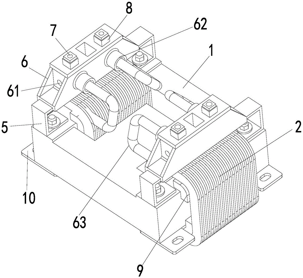
Fig. 1 is a schematic perspective view of a differential-common mode integrated reactor provided in an embodiment of the present invention;
fig. 2 is a schematic front view of a differential-common mode integrated reactor provided in an embodiment of the present invention;
FIG. 3 is a schematic diagram of a differential-to-common mode magnetic circuit of a differential-to-common mode integrated reactor according to an embodiment of the present invention;
fig. 4 is an enlarged schematic structural diagram of a terminal block of a differential-common mode integrated reactor provided in an embodiment of the present invention;
FIG. 5 is a schematic diagram of a differential-common mode integrated reactor provided by an embodiment of the utility model;
fig. 6 is a schematic circuit diagram of an application circuit of the differential-common mode integrated reactor provided by the embodiment of the present invention.
Detailed Description
The foregoing and other technical matters, features and advantages of the present invention will be apparent from the following detailed description of the embodiments, which is to be read in connection with the accompanying drawings. The following description contains various specific details to aid in this understanding, but these details should be construed as merely exemplary. Moreover, descriptions of well-known functions and constructions may be omitted for clarity and conciseness.
In the description of the present invention, it is to be understood that the terms "upper", "lower", "left", "right", "top", "bottom", and the like, indicate orientations or positional relationships based on those shown in the drawings, and are only for convenience in describing the present invention and simplifying the description, but do not indicate or imply that the device or element referred to must have a specific orientation, be constructed in a specific orientation, and be operated, and thus, should not be construed as limiting the present invention.
As shown in fig. 1-4, the differential-mode and common-mode integrated reactor of the present embodiment includes an iron core 1 and two windings 2, the iron core 1 is an EI-type iron core, the windings 2 are disposed on two sides of the iron core 1, and a common-mode magnetic circuit 3 and a differential-mode magnetic circuit 4 are formed in the iron core 1 after the two windings 2 are energized, so that the volume of the apparatus is reduced, and the installation space is saved. A terminal block bracket 5 is arranged above the winding 2, and specifically, the terminal block bracket 5 is fixed on the iron core 1 by bolts. The terminal block support 5 is provided with a terminal block 6, and a conductive block 7 is embedded in the terminal block 6, wherein the conductive block 7 is processed by a copper piece with good conductivity, the external connection is free from cable connection, and a matched circuit board connection point can be arranged, so that the terminal block support can be used as a circuit connection point and a circuit board support piece. Be equipped with waterproof step 8 between conducting block 7 and the terminal platform 6, waterproof step 8 adopts the insulating rubber material for the clearance between conducting block 7 and the terminal platform 6 is in encapsulated situation, can reach water-proof effects, conveniently does water repellent. The conductive block 7 is electrically connected to the winding 2.
Preferably, the winding 2 is formed by winding enameled wires, the winding polyester imide adhesive tape is wound on the surface of the winding 2, the insulation effect is achieved, and in the specific production process, the polyester imide adhesive tape enables the winding 2 to meet IP54 level waterproof performance.
Preferably, iron core 1 includes center pillar 11, air gap structure 12 and side column 13, and side column 13 establishes in center pillar 11 both sides and is kept apart by air gap structure 12, and winding 2 is installed in the side column 13 outside, and air gap structure 12's benefit satisfies winding 2's installation demand, can possess the radiating effect again.
Preferably, a right-angle stay 9 is provided between the side legs 13 and the winding 2, and mainly functions to support the winding 2, reduce leakage loss on the winding 2, and isolate the core 1.
Preferably, the bottom of the iron core 1 is provided with a mounting bracket 10, and the mounting bracket 10 is welded at the bottom of the iron core 1, so that the whole structure is convenient to mount.
Preferably, the terminal block support 5 is rectangular with a notch so that the end does not obstruct the winding 2 when the block support 5 is placed over the winding 2.
Preferably, the terminal block 6 is a trapezoidal plastic part, the front side and the rear side of the terminal block 6 are both provided with wire pressing holes 61, the inner side of the terminal block 6 is provided with a wire connecting hole 62, a wire connecting pipe 63 is installed in the wire connecting hole 62, when the terminal block is used, an enameled wire of the winding 2 penetrates into the wire connecting pipe 63 and is electrically connected with the conductive block 7 through the wire connecting hole 62, and the conductive block 7 and the enameled wire are firmly connected by installing bolts in the wire pressing holes 61.
As shown in fig. 5, the reactor of the present application is provided with four conductive blocks 7, LIN, NIN, LOUT, NOUT, as binding posts, which are respectively connected to a live wire incoming wire, a zero wire incoming wire, a live wire outgoing wire and a zero wire outgoing wire.
As shown in fig. 6, in order to make the rectified output have a dc output with a good effect, an inductor and a capacitor become indispensable important components, and in a high-current rectification module, in order to increase reliability, a multi-channel silicon controlled rectifier module is generally adopted, and due to multi-channel switching phase angle precision errors, common mode and differential mode higher harmonic components exist in the waveform at the rectification rear end. These higher harmonic components are usually combined with an inductor and a capacitor to form a low-pass filter. This application adopts the inductance part to produce poor common mode integrated reactor through design make full use of EI iron core structural feature, structurally through having waterproof, dirt-proof effect concurrently.
The present invention is not limited to the above exemplary embodiments, and any modifications, equivalent replacements, improvements, etc. within the spirit and principle of the present invention should be included in the protection scope of the present invention.