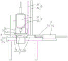
Automatic drilling machine
Technical Field
The utility model relates to a machining device, in particular to an automatic drilling machine.
Background
In furniture manufacture, a cylindrical pad is needed, and the specific structure is a cylindrical wood block, and a hole position is processed in the middle of the cylindrical wood block. When drilling the cylindrical pad, the existing processing mode is generally manual operation, the cylindrical wood block to be processed is placed on a workbench of drilling equipment, drilling is carried out after positioning, and the cylindrical wood block is taken down after completion. This processing method has problems of low speed and low efficiency.
Disclosure of Invention
In order to solve the problems in the prior art, the utility model provides the drilling machine which is efficient and can automatically drill the cylindrical pad.
An automatic drilling machine comprises a rack and a drilling mechanism, wherein a machining station is arranged on the rack, and the automatic drilling machine also comprises a material placing mechanism which is arranged on the rack and used for placing stacked workpieces; the pushing mechanism is arranged on the rack and used for pushing a workpiece positioned at the lowest part in the discharging mechanism to the processing station; the positioning mechanism is arranged on the rack and used for positioning the workpiece on the machining position; the pressing mechanism is arranged on the rack and is used for pressing the workpiece on the processing position; the pushing mechanism is arranged on the rack, and a pushing end of the pushing mechanism is fixedly connected with the drilling mechanism and is used for pushing the drilling mechanism to drill the workpiece on the machining position; and the discharging mechanism is arranged on the rack and used for pushing the drilled workpiece away from the machining station.
The improved discharging mechanism comprises a baffle and two L-shaped limiting plates which are symmetrically arranged and can adjust the distance, an area which can be used for placing workpieces is formed between the baffle and the two limiting plates, and openings for moving out the workpieces at the bottom are formed in the bottoms of the baffle and the two limiting plates.
The material pushing mechanism is further improved to comprise a first pushing piece and a pushing block, the pushing block is opposite to the workpiece at the lowest part of the material discharging mechanism, the first pushing piece is fixedly connected to the rack, and the pushing end of the first pushing piece is fixedly connected with the pushing block and can push the workpiece at the lowest part to move out of the openings at the bottoms of the baffle and the two limiting plates.
The positioning mechanism comprises a first positioning block, a second positioning block and a positioning pushing piece which are arranged on the machine frame and can adjust positions, the positioning surfaces of the first positioning block and the second positioning block are perpendicular to each other, and the positioning pushing piece can push a workpiece to be tightly attached to the positioning surfaces of the first positioning block and the second positioning block.
The discharging mechanism is a discharging pushing piece which is arranged on the rack and can adjust the position of the discharging mechanism, and the second positioning block is fixedly connected with the pushing end of the discharging pushing piece.
The improved structure is characterized in that a discharge hopper is further arranged on the rack, the discharge hopper is opposite to the second positioning block, the first positioning block is opposite to the pushing block, the positioning pushing piece is positioned between the discharge hopper and the pushing block, and the pushing end of the positioning pushing piece faces the processing position.
In a further improvement, the pressing mechanism comprises a second pushing piece fixedly connected to the frame and having a pushing end capable of moving up and down and a pressing plate fixedly connected with the pushing end of the second pushing piece.
In a further improvement, the pushing mechanism comprises a third pushing piece arranged on the rack and a mounting rack fixedly connected with a pushing end of the third pushing piece, and the drilling mechanism is fixedly connected to the mounting rack.
The drilling mechanism comprises a motor and a drill bit which are fixedly connected to the mounting frame, and the output end of the motor is connected with the drill bit.
The improved drilling machine is characterized in that the rack comprises a workbench and a portal frame arranged on the workbench, the discharging mechanism, the material pushing mechanism, the positioning mechanism, the discharging mechanism and the pushing mechanism are all arranged on the workbench, and the drilling mechanism and the pressing mechanism are arranged on the portal frame.
When the drilling machine is used, workpieces are placed in the discharging mechanism, the discharging mechanism pushes the workpiece at the lowest position to move to a machining position and then reset, the positioning mechanism positions the workpieces, the position needing drilling is aligned with the drilling mechanism, then the pressing mechanism presses the workpieces, then the pushing mechanism pushes the drilling mechanism to drill the workpieces, finally the discharging mechanism pushes the machined workpieces away from the machining position, and the drilling operation of all the workpieces is completed in a circulating mode. The automatic drilling machine can automatically process workpieces from feeding, drilling and discharging, and has higher speed and higher efficiency compared with the existing manual operation mode.
Drawings
FIG. 1 is a schematic top view of the present invention;
fig. 2 is a schematic front view of the present invention.
Detailed Description
The present invention will be described in further detail below with reference to specific embodiments and the attached drawings.
Referring to fig. 1 and 2, the automatic drilling machine comprises a frame 1 and a drilling mechanism 2, wherein a processing station is arranged on the frame 1, and the automatic drilling machine further comprises a discharging mechanism 3 which is arranged on the frame 1 and used for placing stacked workpieces; the pushing mechanism 4 is arranged on the rack 1 and used for pushing a workpiece positioned at the lowest position in the discharging mechanism 3 to the processing position; the positioning mechanism 7 is arranged on the rack 1 and used for positioning the workpiece on the processing position; the pressing mechanism 5 is arranged on the rack 1 and is used for pressing the workpiece on the processing position; the pushing mechanism 6 is arranged on the rack 1, and the pushing end of the pushing mechanism is fixedly connected with the drilling mechanism 2 and is used for pushing the drilling mechanism 2 to drill a workpiece on the machining position; and the discharging mechanism 8 is arranged on the machine frame 1 and is used for pushing the drilled workpiece away from the machining position.
As a preferred embodiment, referring to fig. 1 and 2, the discharge mechanism 3 includes a baffle 31 and two L-shaped spacing plates 32 symmetrically arranged and with adjustable spacing, an area for placing a workpiece is formed between the baffle 31 and the two spacing plates 32, and openings for removing the lowest workpiece are provided at the bottoms of the baffle 31 and the two spacing plates 32. In this embodiment, two are adjustable interval, are convenient for adapt to the work piece of different specifications through adjusting interval, when stacking the work piece, because the work piece of action of gravity below shifts out the back from the opening, all the other work pieces can fall by oneself, conveniently process in proper order, do not need additionally to establish other mechanisms, simple structure. In a further improvement, the material pushing mechanism 4 includes a first pushing member 41 and a pushing block 42, the pushing block 42 is opposite to the lowest workpiece of the material discharging mechanism 3, the first pushing member 41 is fixedly connected to the frame 1, and a pushing end of the first pushing member 41 is fixedly connected to the pushing block 42 and can push the lowest workpiece to move out of the openings at the bottoms of the baffle 31 and the two limiting plates 32.
As a preferred embodiment, referring to fig. 1 and 2, the positioning mechanism 7 includes a first positioning block 71, a second positioning block 72, and a positioning pushing member 73, which are all disposed on the frame 1 and are adjustable in position, the positioning surfaces of the first positioning block 71 and the second positioning block 72 are perpendicular to each other, and the positioning pushing member 73 can push the workpiece to be attached to the positioning surfaces of the first positioning block 71 and the second positioning block 72. Because the workpiece pushed to the processing station from the pushing mechanism 4 deviates, the first positioning block 71 and the second positioning block 72 with mutually vertical positioning surfaces are arranged to block the workpiece, and the positioning pushing piece 73 is used for pushing the workpiece to be tightly attached to the positioning surfaces of the first positioning block 71 and the second positioning block 72, so that the positioning is finished. In a further improvement, the discharging mechanism 8 is a discharging pushing member which is arranged on the frame 1 and can adjust the position of the discharging pushing member, and the second positioning block 72 is fixedly connected with a pushing end of the discharging pushing member. For the work piece ejection of compact after conveniently processing be provided with out hopper 9 on the frame 1, specific overall arrangement is: the discharge hopper 9 is opposite to the second positioning block 72, the first positioning block 71 is opposite to the pushing block 42, the positioning pushing piece 73 is positioned between the discharge hopper 9 and the pushing block 42, the pushing end of the positioning pushing piece 73 faces the processing station, and in the structure, the pushing end of the positioning pushing piece 73 faces between the first positioning block 71 and the second positioning block 72, so that a workpiece can be tightly attached to the first positioning block 71 and the second positioning block 72 to realize positioning when the workpiece is pushed. Of course, the positions of the first positioning hole and the second positioning block 72 can be adjusted, and the adjustable positioning device can adapt to workpieces of different specifications and sizes.
As a preferred embodiment, referring to fig. 1 and 2, the pressing mechanism 5 includes a second pushing member 51 fixedly connected to the frame 1 and having a pushing end capable of moving up and down, and a pressing plate 52 fixedly connected to the pushing end of the second pushing member 51. The pressing mechanism 5 can move up and down, and when moving down, the pressing plate 52 can press the upper surface of the workpiece, so that the workpiece can be kept fixed and cannot deviate in the drilling process through pressing. The pushing mechanism 6 comprises a third pushing member 61 arranged on the frame 1 and a mounting frame 62 fixedly connected with a pushing end of the third pushing member 61, and the drilling mechanism 2 is fixedly connected to the mounting frame 62. The drilling mechanism 2 comprises a motor 21 and a drill bit 22 which are both fixedly connected to a mounting frame 62, and the output end of the motor 21 is connected with the drill bit 22. The third pushing piece 61 can push the mounting frame 62 to move up and down, so as to control the drilling mechanism 2 to drill and recover the workpiece.
For further improvement of the above embodiment, referring to fig. 1 and 2, the rack 1 includes a workbench 11 and a portal frame 12 arranged on the workbench 11, the material discharging mechanism 3, the material pushing mechanism 4, the positioning mechanism 7, the discharging mechanism 8 and the pushing mechanism 6 are all arranged on the workbench 11, and the drilling mechanism 2 and the pressing mechanism 5 are arranged on the portal frame 12. In this embodiment, by arranging the gantry 12 and the workbench 11, different components are installed at required positions, so that the whole framework is simple and reliable. In addition, in the above embodiment, the first pushing member 41, the second pushing member 51, the positioning pushing member 73 and the discharging pushing member all adopt the air cylinder or the linear motor.
In the present invention, unless otherwise explicitly specified or limited, the terms "mounted," "connected," "arranged," and the like are to be construed broadly and may, for example, be connected in an arrangement, detachably connected, or integrated; they may be mechanically coupled, directly coupled, or indirectly coupled through intervening agents, both internally and/or in any other manner known to those skilled in the art. The specific meanings of the above terms in the present invention can be understood by those skilled in the art according to specific situations.
While the utility model has been described in conjunction with the specific embodiments set forth above, it is evident that many alternatives, modifications, and variations will be apparent to those skilled in the art in light of the foregoing description. Accordingly, it is intended to embrace all such alternatives, modifications, and variations that fall within the spirit and scope of the appended claims.