Background
Rectification is used as the most widely and important mass transfer separation operation unit in the chemical production process, and more than 90% of the product is proposed and recovered by rectification, 40-70% of the energy consumption in the chemical production process is used for separation, and the rectification energy consumption accounts for more than 90% of the energy consumption. Although the rectification technology is quite mature and widely applied, energy conservation and emission reduction are vigorously advocated in China, and energy conservation in the rectification process is more and more concerned. Most of the existing hydrogen peroxide concentration adopts a conventional rectification mode, so that the treatment capacity is large, the energy consumption is high, a new technology is urgently needed to reduce the energy consumption and save the operation cost.
The heat pump rectification is based on the principle of a heat pump, the steam coming out of the tower top does not need to be condensed, the temperature and the pressure of the steam are directly increased through a compressor, the enthalpy value of the steam is increased, then the steam is used as a heat source of a reboiler to heat materials, the latent heat of the steam at the tower top is fully utilized, the consumption of the generated steam is reduced, and the operation cost is reduced. According to different external energy consumed by the heat pump, the heat pump rectification mode includes indirect heat pump rectification, tower top gas direct compression type heat pump rectification, split heat pump rectification, flash distillation reboiler type heat pump rectification and the like. The application of the energy-saving technology can bring greater economic benefits for enterprises.
SUMMERY OF THE UTILITY MODEL
The utility model aims to overcome the defects of the prior art and provide the hydrogen peroxide heat pump rectifying device which is energy-saving, consumption-reducing and cost-saving.
In order to solve the technical problems, the utility model is realized by adopting the following technical scheme: the hydrogen peroxide solution heat pump rectifying device comprises a rectifying tower, a falling film evaporator and a preheater, and is characterized in that: an inlet of the preheater is connected with a dilute hydrogen peroxide feeding pipeline, an outlet of the preheater is connected with a material inlet of the falling-film evaporator, a steam outlet of the falling-film evaporator is connected with a gas inlet at the bottom of the rectifying tower, and a liquid outlet at the bottom of the rectifying tower is connected with a liquid inlet of the falling-film evaporator; a liquid outlet at the bottom of the falling-film evaporator is connected with a forced circulation pump, an outlet of the forced circulation pump is respectively connected with a liquid inlet at the top of the falling-film evaporator and the other inlet of the preheater through a forced circulation return pipeline and a forced circulation extraction pipeline, the other outlet of the preheater is connected with a concentrated hydrogen peroxide extraction pipeline, a condensate outlet of the falling-film evaporator is connected with a liquid inlet of a buffer tank, a liquid outlet at the bottom of the buffer tank is connected with a return pump, an outlet of the return pump is respectively connected with a water extraction pipeline and a return port at the top of the rectifying tower, and a gas outlet at the top of the buffer tank is connected with a vacuum system; and a gas outlet at the top of the rectifying tower is connected with a gas inlet of a compressor, a gas outlet of the compressor is connected with a gas inlet of the falling film evaporator, and the falling film evaporator is also provided with a raw steam inlet.
Preferably, a gas outlet at the top of the buffer tank is connected with a condenser, a gas outlet of the condenser is connected with a vacuum system, and an outlet of the condenser is connected with a receiving tank.
Preferably, the compressor is a centrifugal compressor, a roots compressor or a screw compressor.
Preferably, the preheater adopts a spiral winding tube type heat exchanger, a shell and tube type heat exchanger, a spiral plate type heat exchanger or a plate type heat exchanger.
Preferably, the condenser adopts a spiral wound tube type heat exchanger, a shell and tube type heat exchanger, a spiral plate type heat exchanger or a plate type heat exchanger.
Preferably, the system operation pressure of the falling film evaporator is 5-50kPa absolute and the compressor pressure ratio is 1-5.
The improved hydrogen peroxide heat pump rectifying device has the advantages that steam at the top of the rectifying tower is pressurized and heated by the compressor to be used as a heat source of the falling film evaporator, the consumption of raw steam of the falling film evaporator is greatly reduced, the raw steam is saved by more than 90%, the total energy saving of the system is more than 50%, the energy saving effect is remarkable, a large amount of operating cost is saved, and the practical economic value is brought to enterprises.
Detailed Description
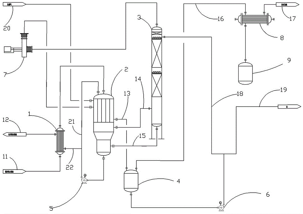
The drawings show the structure of the utility model, and the details thereof are further described below with reference to the drawings. In the embodiment, the hydrogen peroxide heat pump rectifying device comprises a rectifying tower 3, a falling-film evaporator 2 and a preheater 1, wherein an inlet of the preheater 1 is connected with a dilute hydrogen peroxide feeding pipeline 11, an outlet of the preheater 1 is connected with a material inlet of the falling-film evaporator 2, a steam outlet of the falling-film evaporator 2 is connected with a gas inlet at the bottom of the rectifying tower 3, and a liquid outlet at the bottom of the rectifying tower 3 is connected with a liquid inlet of the falling-film evaporator 2; a liquid outlet at the bottom of the falling-film evaporator 2 is connected with a forced circulation pump 5, an outlet of the forced circulation pump 5 is respectively connected with a liquid inlet at the top of the falling-film evaporator 2 and another inlet of the preheater 1 through a forced circulation return pipeline 21 and a forced circulation extraction pipeline 22, another outlet of the preheater 1 is connected with a concentrated hydrogen peroxide extraction pipeline 12, a condensate outlet of the falling-film evaporator 2 is connected with a liquid inlet of the buffer tank 4, a liquid outlet at the bottom of the buffer tank 4 is connected with a return pump 6, an outlet of the return pump 6 is respectively connected with a water extraction pipeline 19 and a return port at the top of the rectifying tower 3, and a gas outlet at the top of the buffer tank 4 is connected with a vacuum system 17; the gas outlet at the top of the rectifying tower 3 is connected with the gas inlet of a compressor 7, the gas outlet of the compressor 7 is connected with the gas inlet of the falling film evaporator 2, the falling film evaporator 2 is also provided with a raw steam inlet, and the raw steam inlet is connected with raw steam through a raw steam heating pipeline 20.
As a further improved specific embodiment, a condenser 8 is connected to a gas outlet at the top of the buffer tank 4, a vacuum system 17 is connected to a gas outlet of the condenser 8, and a receiving tank 9 is connected to an outlet of the condenser 8. The condenser 8 is arranged to reduce the temperature of the gas exiting the buffer tank 4.
As a more improved embodiment, the compressor 7 is a centrifugal compressor, a roots compressor or a screw compressor.
As a further improved specific embodiment, the preheater 1 adopts a spiral wound tube type heat exchanger, a shell and tube type heat exchanger, a spiral plate type heat exchanger or a plate type heat exchanger.
In a further improved embodiment, the condenser 8 is a spiral wound tube heat exchanger, a shell and tube heat exchanger, a spiral plate heat exchanger or a plate heat exchanger.
As a further improved specific embodiment, the system operation pressure of the falling-film evaporator 2 is 5-50kPa absolute, the pressure ratio of a compressor is 1-5, the compressor compresses gas discharged from the top of the rectifying tower 3 at the pressure ratio of 1-5, and the pressure of gas discharged from the outlet of the compressor is consistent with the system operation pressure of the falling-film evaporator 2.
The specific process implementation steps of the utility model are described as follows:
in the first embodiment, 30% of dilute hydrogen peroxide water flow 26t/h enters the preheater 1 through the dilute hydrogen peroxide feeding pipeline 11, and flows into the falling film evaporator 2 after being preheated to 45 ℃ by the preheater 1, the system heats and gasifies the material in the falling film evaporator 2 through the raw steam 20 when the system is started, the absolute pressure of the system is 10kPa, the evaporation temperature of the falling film evaporator 2 is 55 ℃, the evaporated gas enters the rectifying tower 3 from the falling film evaporator 2 through the material steam pipeline 14, the liquid at the bottom of the rectifying tower 3 flows back into the falling film evaporator 2 through the liquid return pipeline 15, the gas at the top of the rectifying tower 3 enters the compressor 7, the temperature of the gas entering the compressor is 45 ℃, the gas is pressurized and heated by the compressor 7, the gas is changed into 75 ℃ steam and enters the falling film evaporator 2 for heat exchange, the system does not need the raw steam to heat the falling film evaporator 2 after normal operation, the condensate after heat exchange enters the buffer tank 4 from the falling film evaporator 2 through the cold condensation water pipeline 13, the buffer tank 4 is connected with a vacuum pipeline 16, the vacuum pipeline 16 is connected with a condenser 8, the condenser 8 is connected with a vacuum system 17, the whole system is evaporated and rectified under negative pressure through the vacuum system 17, condensate water in the condenser 8 flows into a receiving tank 9, part of the condensate water in the buffer tank 4 flows back into a rectifying tower 3 through a return pipeline 18 through a return pump 6, the return flow rate is 3.5t/h, part of the condensate water flows out 12.2t/h through a water extraction pipeline 19, part of materials in the falling-film evaporator 2 flows back into the top of the falling-film evaporator 2 through a forced circulation return pipeline 21 through a forced circulation pump 5, and part of the materials are extracted out to the preheater 1 through a forced circulation extraction pipeline 22 and exchange heat with feeding materials, the extraction flow rate is 13.8t/h, and the concentration of hydrogen peroxide is 55%.
In the second embodiment, 27% of the flow rate of the dilute hydrogen peroxide enters the preheater 1 through the dilute hydrogen peroxide feeding pipeline 11, the dilute hydrogen peroxide enters the falling film evaporator 2 after being preheated to 45 ℃ by the preheater 1, the material in the falling film evaporator 2 is heated and gasified by the raw steam 20 when the system is started, the absolute pressure of the system is 10kPa, the evaporation temperature of the falling film evaporator 2 is 55 ℃, the evaporated gas enters the rectifying tower 3 from the falling film evaporator 2 through the material steam pipeline 14, the liquid at the bottom of the rectifying tower 3 reflows into the falling film evaporator 2 through the liquid reflowing pipeline 15, the gas at the top of the rectifying tower 3 enters the compressor 7, the temperature of the gas entering the compressor is 45 ℃, the gas is changed into 75 ℃ steam after being pressurized and heated by the compressor 7, the steam enters the falling film evaporator 2 for heat exchange, the condensate after the heat exchange enters the buffer tank 4 from the falling film evaporator 2 through the water condensing pipeline 13, the vacuum pipeline 16 is connected to the buffer tank 4, and the vacuum pipeline 16 is connected with the condenser 8, the condenser 8 is connected with a vacuum system 17, the whole system is evaporated and rectified under negative pressure through the vacuum system 17, condensate water in the condenser 8 flows into the receiving tank 9, part of the condensate water in the buffer tank 4 flows back into the rectifying tower 3 through a return pipeline 18 through a return pump 6, the reflux flow is 1.1t/h, part of the condensate water flows out 9.0t/h through a water extraction pipeline 19, part of materials in the falling-film evaporator 2 flows back into the top of the falling-film evaporator 5 through a forced circulation return pipeline 21 through a forced circulation pump 5, and part of the materials are extracted out of the preheater 1 through a forced circulation extraction pipeline 22, and after heat exchange with feeding materials, the extraction flow is 11.9t/h, and the concentration of hydrogen peroxide is 50%.
In summary, the above description is only a preferred embodiment of the present invention, and is not intended to limit the scope of the present invention. Any modification, equivalent replacement, or improvement made within the spirit and principle of the present invention should be included in the protection scope of the present invention.