CN215349561U - Leg fixing device for femoral vein puncture catheter - Google Patents
Leg fixing device for femoral vein puncture catheter Download PDFInfo
- Publication number
- CN215349561U CN215349561U CN202121649968.9U CN202121649968U CN215349561U CN 215349561 U CN215349561 U CN 215349561U CN 202121649968 U CN202121649968 U CN 202121649968U CN 215349561 U CN215349561 U CN 215349561U
- Authority
- CN
- China
- Prior art keywords
- fixing
- connecting rod
- leg
- femoral vein
- accommodating
- Prior art date
- Legal status (The legal status is an assumption and is not a legal conclusion. Google has not performed a legal analysis and makes no representation as to the accuracy of the status listed.)
- Active
Links
Images


Landscapes
- Orthopedics, Nursing, And Contraception (AREA)
Abstract
一种用于股静脉穿刺置管的腿部固定装置,其包括腿部容纳件;所述腿部容纳件包括用于固定腿部膝盖上方的第一容纳件,和用于固定腿部膝盖下方的第二容纳件;所述第一容纳件和第二容纳件之间通过连接件活动连接;通过此种方式先确定病人腿部外展姿势及角度后,将病人腿部置于第一容纳件与第二容纳件内部并固定,以实现维持病人保持腿部外展姿势的目的。

A leg fixing device for femoral vein puncture cannulation, comprising a leg holder; the leg holder comprises a first holder for fixing the upper part of the knee of the leg, and a first holder for fixing the lower part of the knee of the leg the second accommodating part; the first accommodating part and the second accommodating part are movably connected by connecting parts; in this way, after first determining the abduction posture and angle of the patient's leg, place the patient's leg in the first accommodating part The part is fixed inside and fixed with the second accommodating part, so as to achieve the purpose of maintaining the patient's leg abduction posture.
Description
技术领域technical field
本实用新型属于医疗器械技术领域,具体涉及为一种用于股静脉穿刺置管的腿部固定装置。The utility model belongs to the technical field of medical devices, and in particular relates to a leg fixing device used for femoral vein puncture and cannulation.
背景技术Background technique
股静脉是下肢深静脉之一,位于大腿根部。股静脉在人体的位置相对表浅,是静脉穿刺以及留置导管等常用部位,特别是股静脉处留置双腔/三腔大流量导管用来进行血液净化及相关治疗模式用于治疗与抢救重症患者时,是临床较为常用的静脉置管方法之一。The femoral vein is one of the deep veins of the lower extremity, located at the root of the thigh. The femoral vein is relatively superficial in the human body, and is a common site for venipuncture and indwelling catheters, especially indwelling double-lumen/three-lumen high-flow catheters at the femoral vein for blood purification and related treatment modes for the treatment and rescue of critically ill patients It is one of the most commonly used venous catheterization methods in clinical practice.
在进行股静脉置管操作或血液净化治疗时,需要将术侧或置管侧腿部进行一定角度的外展,以保证血管位置或治疗时体外循环血流的稳定性,但是如果需要患者自己保持腿部外展的被迫体位,既很难长时间保持体位,也没有舒适性。重症患者进行血液净化治疗时,根据不同治疗方式所需要的时间也不同,较短时间的治疗需要4小时左右,如果是持续血液净化治疗则需要24-72小时,甚至更长时间,患者很难主动保持长时间腿部外展的被动体位。此外,医生在进行股静脉置管时,患者会因为局部穿刺的疼痛感以及较长时间被动体位后的疲劳不适感,引起术侧肢体移动,改变穿刺置管位置,引发不良反应。例如,穿刺时体位移动,有可能会导致穿刺失败甚至局部出血;血液净化治疗中体位发生改变,可能会引起血液循环不稳定,缺血报警甚至血液断流发生,不仅会延长治疗时间,还会出现治疗管路内压力增高,严重者还会发生体外循环管路凝血甚至堵塞,最终无法继续进行治疗。不但达不到医生既定的治疗量与预期治疗效果,还会增加病人花费,增加住院时间,增加了病人、家庭和社会的经济负担。因此为了保证穿刺置管与血液净化治疗时腿部长期保持外展姿势,需要一种用于股静脉置管与治疗时的腿部固定装置。When performing femoral vein catheterization or blood purification treatment, it is necessary to abduct the operation side or the leg at the side of catheterization at a certain angle to ensure the stability of blood vessel position or extracorporeal circulation during treatment. The forced position of maintaining leg abduction is neither difficult nor comfortable to hold for long periods of time. When blood purification treatment is performed on critically ill patients, the time required varies according to different treatment methods. Shorter treatment takes about 4 hours, and continuous blood purification treatment takes 24-72 hours, or even longer. It is difficult for patients. A passive position that actively maintains abduction of the legs for long periods of time. In addition, when doctors perform femoral vein catheterization, the patient will move the operative side due to the pain of local puncture and the fatigue and discomfort after a long passive position, which will cause the movement of the operative side, change the location of puncture and catheterization, and cause adverse reactions. For example, if the body position moves during puncture, it may lead to puncture failure or even local bleeding; if the body position changes during blood purification treatment, it may cause blood circulation instability, ischemia alarm or even blood cutoff, which will not only prolong the treatment time, but also The pressure in the treatment pipeline increases, and in severe cases, coagulation or even blockage of the extracorporeal circulation pipeline may occur, and eventually the treatment cannot be continued. Not only does it fail to reach the doctor's prescribed treatment volume and expected treatment effect, but it also increases the patient's cost, increases the length of hospital stay, and increases the economic burden on the patient, family and society. Therefore, in order to ensure the long-term abduction posture of the legs during puncture catheterization and blood purification treatment, a leg fixing device for femoral vein catheterization and treatment is required.
本实用新型针对上述问题,提供一种用于股静脉穿刺置管与以股静脉置管为基础建立体外循环行血液净化治疗的腿部固定装置。In view of the above problems, the utility model provides a leg fixing device used for femoral vein puncture and catheterization and establishment of extracorporeal circulation for blood purification treatment based on femoral vein catheterization.
实用新型内容Utility model content
为了克服背景技术中提出的问题,本实用新型提供一种用于股静脉穿刺置管的腿部固定装置。In order to overcome the problems raised in the background art, the present invention provides a leg fixing device for femoral vein puncture and cannulation.
一种用于股静脉穿刺置管的腿部固定装置,其包括腿部容纳件;所述腿部容纳件包括用于固定腿部膝盖上方的第一容纳件,和用于固定腿部膝盖下方的第二容纳件;所述第一容纳件和第二容纳件之间通过连接件活动连接;通过此种方式先确定病人腿部外展姿势及角度后,将病人腿部置于第一容纳件与第二容纳件内部并固定,以实现维持病人保持腿部外展姿势的目的。A leg fixing device for femoral vein puncture cannulation, comprising a leg holder; the leg holder comprises a first holder for fixing the upper part of the knee of the leg, and a first holder for fixing the lower part of the knee of the leg the second accommodating part; the first accommodating part and the second accommodating part are movably connected by a connecting piece; in this way, after first determining the abduction posture and angle of the patient's leg, place the patient's leg in the first accommodating part The part is fixed inside the second accommodating part, so as to achieve the purpose of maintaining the patient's leg abduction posture.
进一步,所述连接件包括设置在第一容纳件内侧的第一连接杆,和设置在第二容纳件内侧的第二连接杆,第一连接杆和第二连接杆之间转动连接;通过改变第一连接杆和第二连接杆之间的角度,实现调节第一容纳件和第二容纳件之间的相对角度,并实现对大腿外展角度、小腿和大腿之间夹角的有效调节。Further, the connecting member includes a first connecting rod disposed inside the first accommodating member, and a second connecting rod disposed inside the second accommodating member, and the first connecting rod and the second connecting rod are rotatably connected; by changing The angle between the first connecting rod and the second connecting rod can adjust the relative angle between the first accommodating part and the second accommodating part, and effectively adjust the abduction angle of the thigh and the angle between the calf and the thigh.
进一步,在所述第一连接杆和第二连接杆的自由端分别设置连接板,连接板的厚度小于第一连接杆/第二连接杆的厚度;且在连接板的上方和下方设置转轴,转轴上下贯穿连接板;此种设置保证第一连接杆和第二连接杆之间的无障碍自由旋转。Further, connecting plates are respectively provided at the free ends of the first connecting rod and the second connecting rod, and the thickness of the connecting plate is smaller than the thickness of the first connecting rod/the second connecting rod; and a rotating shaft is arranged above and below the connecting plate, The rotating shaft penetrates the connecting plate up and down; this arrangement ensures the barrier-free and free rotation between the first connecting rod and the second connecting rod.
进一步,设置在所述第一连接杆的连接板和设置在第二连接杆的连接板的总厚度等于第一连接杆或第二连接杆的厚度;此种前后厚度相一致的设置方便临床的操作。Further, the total thickness of the connecting plate disposed on the first connecting rod and the connecting plate disposed on the second connecting rod is equal to the thickness of the first connecting rod or the second connecting rod; operate.
进一步,在所述连接板的上端或下端设置螺纹固定孔,以及与螺纹固定孔匹配使用的固定帽;临床上将第一连接杆和第二连接杆之间调整至合适夹角后,再将固定帽拧入螺纹固定孔有效固定第一连接杆和第二连接杆的相对位置。Further, a threaded fixing hole is arranged on the upper end or the lower end of the connecting plate, and a fixing cap matched with the threaded fixing hole is used; after clinically adjusting the angle between the first connecting rod and the second connecting rod to an appropriate angle, The fixing cap is screwed into the threaded fixing hole to effectively fix the relative positions of the first connecting rod and the second connecting rod.
进一步,所述螺纹固定孔贯穿上方连接板,并伸入下方连接板;此种设置能实现对第一连接杆和第二连接杆间夹角的有效固定。Further, the threaded fixing hole penetrates through the upper connecting plate and extends into the lower connecting plate; this arrangement can effectively fix the angle between the first connecting rod and the second connecting rod.
进一步,所述第一连接杆和第二连接杆均设置为可伸缩型;可伸缩型连接杆的设置有效满足对第一容纳件和第二容纳件进行随意调节的需求。Further, the first connecting rod and the second connecting rod are both set to be telescopic; the setting of the telescopic connecting rod can effectively meet the requirement of arbitrarily adjusting the first accommodating member and the second accommodating member.
进一步,所述第一容纳件设置为具有开口的C形固定环一,在C形固定环一的外侧设置用于调整C形固定环一的松紧度的固定结构,固定结构在C形固定环一外侧的位置可调;使用时,根据不同病人的需求调整固定结构相对C形固定环一的位置和松紧度,最终实现对大腿的有效固定作用。Further, the first accommodating member is set as a C-shaped fixing ring 1 with an opening, and a fixing structure for adjusting the tightness of the C-shaped fixing ring 1 is arranged on the outer side of the C-shaped fixing ring 1, and the fixing structure is in the C-shaped fixing ring. The position of the outer side can be adjusted; when in use, the position and tightness of the fixing structure relative to the C-shaped fixing ring 1 can be adjusted according to the needs of different patients, and finally the effective fixing effect on the thigh can be realized.
进一步,所述固定结构为设置在C形固定环一外侧靠近上端开口处的固定带一,固定带一的两端通过连接结构活动连接;使用时,C形固定环一外套在患者的大腿外围,再通过连接结构调节固定带一的松紧度,以保证对大腿的固定效果。Further, the fixing structure is a fixing belt 1 arranged on the outer side of the C-shaped fixing ring, close to the opening of the upper end, and the two ends of the fixing belt 1 are movably connected by the connecting structure; when in use, the C-shaped fixing ring jacket is on the periphery of the patient's thigh. , and then adjust the tightness of the fixing belt 1 through the connection structure to ensure the fixing effect on the thigh.
进一步,所述连接结构包括设置在固定带一第一端的固定框,和设置在固定带一第二端外侧的粘贴结构;通过此种方式将固定带一的第二端穿过固定框,将固定带一调节至合适长度后,再翻折回使得固定带一第二端外侧的粘贴结构互相重合,实现对C形固定环一的内径、位置的固定。Further, the connection structure includes a fixing frame arranged at the first end of the fixing band, and a sticking structure arranged outside the second end of the fixing band; in this way, the second end of the fixing band 1 is passed through the fixing frame, After adjusting the fixing band 1 to a suitable length, it is folded back so that the sticking structures on the outside of the second end of the fixing band 1 overlap each other, so as to fix the inner diameter and position of the C-shaped fixing ring 1.
进一步,在所述固定带一的第二端设置用于容纳放置静脉置管的置管区域,以保证对静脉置管的有效固定。Further, a catheter placement area for accommodating the venous catheter is provided at the second end of the fixing band 1, so as to ensure the effective fixation of the venous catheter.
进一步,所述置管区域设置为固定卡槽,固定卡槽设置在粘贴结构的对面;在固定卡槽上方还设置用于固定静脉置管的粘贴带;通过此种方式将静脉置管放置在固定卡槽内,再利用粘贴带对静脉置管进行有效固定。Further, the catheter placement area is set as a fixed clip slot, and the fixed clip slot is arranged on the opposite side of the sticking structure; an adhesive tape for fixing the venous tube placement is also set above the fixed clip slot; in this way, the venous placement tube is placed on the In the fixing slot, use the adhesive tape to effectively fix the venous catheter.
进一步,所述固定卡槽至少设置2个,2或多个固定卡槽平行位于固定带一的第二端;此种设置能够满足临床上对静脉置管的固定需求。Further, there are at least two fixed clip grooves, and two or more fixed clip slots are located parallel to the second end of the first fixed belt; such a configuration can meet the clinical requirements for the fixation of the venous catheter.
进一步,在所述固定带一第二端设置置管区域的位置设置加厚带,加厚带的设置能够保证固定卡槽的深度。Further, a thickened belt is arranged at the position where the tube placement area is arranged at the second end of the fixing belt, and the arrangement of the thickened belt can ensure the depth of the fixing slot.
进一步,所述固定结构还包括设置在C形固定环一外侧靠近下端开口处的固定带二,固定带二的两端通过连接结构活动连接;通过连接结构调节固定带二的松紧度,进一步保证C形固定环一对大腿的固定效果。Further, the fixing structure also includes a second fixing belt arranged on the outer side of the first C-shaped fixing ring and close to the opening of the lower end, and the two ends of the second fixing belt are movably connected by the connecting structure; the tightness of the second fixing belt is adjusted through the connecting structure to further ensure The fixed effect of a pair of thighs by a C-shaped fixing ring.
进一步,所述第二容纳件设置为具有开口的C形固定环二,在C形固定环二外侧靠近上端开口和/或靠近下端开口的位置设置固定带二,固定带二的两端通过连接结构活动连接;通过连接结构调节固定带二的松紧度,进一步保证C形固定环二对小腿的固定效果。Further, the second accommodating member is set as a C-
进一步,所述C形固定环一下端的环壁具有坡度,以保证大腿下方的膝盖处不会发生悬空。Further, the ring wall at the lower end of the C-shaped fixing ring has a slope, so as to ensure that the knee below the thigh does not hang.
进一步,所述C形固定环一和C形固定环二选用施外力可改变延展度且有弹性的材质;此种材质可掰开,可固定,还能很好地恢复原样,方便将腿部很好地固定在第一容纳件和第二容纳件的内部,方便操作。Further, the first C-shaped fixing ring and the second C-shaped fixing ring are made of materials that can change the ductility and elasticity by applying external force; this material can be broken apart, fixed, and can be restored to its original state, which is convenient for the legs. It is well fixed inside the first accommodating part and the second accommodating part, which is convenient for operation.
进一步,在所述C形固定环一和C形固定环二的外侧设置有保证患者舒适度的外棉套。Further, an outer cotton cover to ensure the comfort of the patient is provided on the outer sides of the first C-shaped fixing ring and the second C-shaped fixing ring.
本实用新型的有益效果:1、通过设置容纳大腿的第一容纳件,和用于容纳小腿的第二容纳件,并在第一容纳件和第二容纳件的外围设置能够调整松紧度的固定结构,有效保证了患者在进行股静脉置管操作与血液净化治疗时腿部能够长期保持外展的姿势,克服了患者很难自主采取腿部外展姿势的困难;还能够根据不同患者作适应性调整,以满足不同患者的需求;2、半开放的C形固定环的设置能够很好地暴露管路的位置,并通过在固定带一的对应位置设置置管区域,很好地保证了对静脉置管的有效固定效果,避免发生脱管的现象;3、通过在第一容纳件的下端进行坡度设置,保证患者膝盖处不会发生悬空,显著增加患者大腿部的稳定性,和患者被迫保持腿部外展体位的舒适度;4、通过在第一容纳件和第二容纳件之间设置连接件,有效满足根据临床需求调节大腿和小腿外展姿势的目的,结构简单,操作方便。The beneficial effects of the present invention are as follows: 1. By arranging a first accommodating piece for accommodating the thigh and a second accommodating piece for accommodating the lower leg, and setting a fixation capable of adjusting the tightness on the periphery of the first accommodating piece and the second accommodating piece The structure effectively ensures that the patient can maintain the abducted posture of the legs for a long time during the femoral vein catheterization and blood purification treatment, and overcomes the difficulty that the patient can not take the leg abduction posture independently; it can also be adapted according to different patients. It can be adjusted to meet the needs of different patients; 2. The setting of the semi-open C-shaped fixing ring can well expose the position of the pipeline. The effective fixation effect on the venous catheter can avoid the phenomenon of tube detachment; 3. By setting the slope at the lower end of the first accommodating member, it can ensure that the patient's knee will not be suspended, and significantly increase the stability of the patient's thigh, and The patient is forced to maintain the comfort of the leg abduction position; 4. By arranging a connecting piece between the first accommodating part and the second accommodating part, the purpose of adjusting the thigh and calf abduction posture according to clinical needs is effectively met, and the structure is simple and Easy to operate.
附图说明Description of drawings
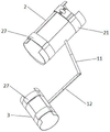
图1为本实用新型的整体结构示意图;Fig. 1 is the overall structure schematic diagram of the present utility model;
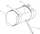
图2为本实用新型中第一容纳件和第一连接杆的结构示意图;2 is a schematic structural diagram of a first accommodating member and a first connecting rod in the utility model;
图3为本实用新型中固定带一的连接结构部分的局部放大结构示意图;Fig. 3 is the partial enlarged structural schematic diagram of the connecting structure part of the fixing belt 1 in the utility model;
图4为本实用新型中固定带一的连接结构部分的局部放大结构前视示意图;Fig. 4 is the partial enlarged structural front view schematic diagram of the connecting structure part of the fixing belt 1 in the utility model;
图5为本实用新型中第一连接杆和第二连接杆连接处的放大结构示意图;Fig. 5 is the enlarged structural schematic diagram of the connection between the first connecting rod and the second connecting rod in the present invention;
图6为本实用新型中第一连接杆或第二连接杆的局部放大结构示意图;Fig. 6 is the partial enlarged structural schematic diagram of the first connecting rod or the second connecting rod in the utility model;
图中,11、第一连接杆;12、第二连接杆;13、连接板;14、转轴;15、螺纹固定孔;16、固定帽;2、C形固定环一;21、固定带一;22、固定框;23、粘贴结构;24、固定卡槽;25、粘贴带;26、加厚带;27、固定带二;3、C形固定环二。In the figure, 11, the first connecting rod; 12, the second connecting rod; 13, the connecting plate; 14, the rotating shaft; 15, the threaded fixing hole; 16, the fixing cap; 2, the C-shaped fixing ring; 22. Fixed frame; 23. Paste structure; 24. Fixed card slot; 25. Adhesive tape; 26. Thickened tape; 27. Fixed tape two;
具体实施方式Detailed ways
以下通过特定的具体实施例对本实用新型实施例中的技术方案进行清楚、完整地描述,显然,所描述的实施例仅仅是本实用新型一部分实施例,而不是全部的实施例,本领域技术人员可由本说明书所揭露的内容轻易地了解本实用新型的其他优点与功效。本实用新型还可以通过另外不同的具体实施方式加以实施或应用,在不冲突的情况下,以下实施例及实施例中的特征可以相互组合,基于本实用新型中的实施例,本领域普通技术人员在没有做出创造性劳动前提下所获得的所有其他实施例,都属于本实用新型保护的范围。The technical solutions in the embodiments of the present invention will be clearly and completely described below through specific specific embodiments. Obviously, the described embodiments are only a part of the embodiments of the present invention, rather than all the embodiments. Those skilled in the art Other advantages and functions of the present invention can be easily understood from the contents disclosed in this specification. The present invention can also be implemented or applied through other different specific embodiments. If there is no conflict, the following embodiments and the features in the embodiments can be combined with each other. Based on the embodiments of the present invention, ordinary skills in the art All other embodiments obtained by personnel without creative work fall within the protection scope of the present invention.
实施例1Example 1
请参照图1-图6,本实施例中的一种用于股静脉穿刺置管的腿部固定装置,其包括腿部容纳件;腿部容纳件包括用于固定腿部膝盖上方的第一容纳件,和用于固定腿部膝盖下方的第二容纳件;第一容纳件和第二容纳件之间通过连接件活动连接;通过此种方式先确定病人腿部外展姿势及角度后,将病人腿部置于第一容纳件与第二容纳件内部并固定,以实现维持病人保持腿部外展姿势的目的。Please refer to FIG. 1 to FIG. 6 , a leg fixing device for femoral vein puncture and cannulation in this embodiment includes a leg accommodating member; the leg accommodating member includes a first A accommodating piece, and a second accommodating piece for fixing the leg below the knee; the first accommodating piece and the second accommodating piece are movably connected by a connecting piece; in this way, after first determining the abduction posture and angle of the patient's legs, The patient's leg is placed inside the first accommodating part and the second accommodating part and fixed, so as to achieve the purpose of maintaining the patient's leg abduction posture.
连接件包括设置在第一容纳件内侧的第一连接杆11,和设置在第二容纳件内侧的第二连接杆12,第一连接杆11和第二连接杆12之间转动连接;通过改变第一连接杆11和第二连接杆12之间的角度,实现调节第一容纳件和第二容纳件之间的相对角度,并实现对大腿外展角度、小腿和大腿之间夹角的有效调节。The connecting piece includes a first connecting
在第一连接杆11和第二连接杆12的自由端分别设置连接板13,连接板13的厚度小于第一连接杆11/第二连接杆12的厚度;且在连接板13的上方和下方设置转轴14,转轴14上下贯穿连接板13;此种设置保证第一连接杆11和第二连接杆12之间的无障碍自由旋转。Connecting
设置在第一连接杆11的连接板13和设置在第二连接杆12的连接板13的总厚度等于第一连接杆11或第二连接杆12的厚度;此种前后厚度相一致的设置方便临床的操作。The total thickness of the connecting
在连接板13的上端或下端设置螺纹固定孔15,以及与螺纹固定孔15匹配使用的固定帽16;临床上将第一连接杆11和第二连接杆12之间调整至合适夹角后,再将固定帽16拧入螺纹固定孔15有效固定第一连接杆11和第二连接杆12的相对位置。螺纹固定孔15贯穿上方连接板13,并伸入下方连接板13;此种设置能实现对第一连接杆11和第二连接杆12间夹角的有效固定。第一连接杆11和第二连接杆12均设置为可伸缩型;可伸缩型连接杆的设置有效满足对第一容纳件和第二容纳件进行随意调节的需求。A threaded fixing
第一容纳件设置为具有开口的C形固定环一2,在C形固定环一2的外侧设置用于调整C形固定环一2的松紧度的固定结构,固定结构在C形固定环一2外侧的位置可调;使用时,根据不同病人的需求调整固定结构相对C形固定环一2的位置和松紧度,最终实现对大腿的有效固定作用。The first accommodating member is set as a C-shaped fixing ring-2 with an opening, and a fixing structure for adjusting the tightness of the C-shaped fixing ring-2 is arranged on the outer side of the C-shaped fixing ring-2, and the fixing structure is located in the C-shaped fixing ring-1. 2. The position of the outer side can be adjusted; when in use, the position and tightness of the fixing structure relative to the C-shaped fixing ring-2 can be adjusted according to the needs of different patients, and finally the effective fixing effect on the thigh can be realized.
固定结构为设置在C形固定环一2外侧靠近上端开口处的固定带一21,固定带一21的两端通过连接结构活动连接;使用时,C形固定环一2外套在患者的大腿外围,再通过连接结构调节固定带一21的松紧度,以保证对大腿的固定效果。The fixing structure is a fixing belt-21 arranged on the outer side of the C-shaped fixing ring-2 near the opening of the upper end, and the two ends of the fixing belt-21 are movably connected by the connecting structure; when in use, the C-shaped fixing ring-2 is covered on the periphery of the patient's thigh. , and then adjust the tightness of the fixing belt 1 21 through the connection structure to ensure the fixing effect on the thigh.
连接结构包括设置在固定带一21第一端的固定框22,和设置在固定带一21第二端外侧的粘贴结构23;通过此种方式将固定带一21的第二端穿过固定框22,将固定带一21调节至合适长度后,再翻折回使得固定带一21第二端外侧的粘贴结构23互相重合,实现对C形固定环一2的内径、位置的固定。The connection structure includes a fixing
第二容纳件设置为具有开口的C形固定环二3,在C形固定环二3外侧靠近上端开口和/或靠近下端开口的位置设置固定带二27,固定带二27的两端通过连接结构活动连接;通过连接结构调节固定带二27的松紧度,进一步保证C形固定环二3对小腿的固定效果。The second accommodating member is configured as a C-shaped
C形固定环一2下端的环壁具有坡度,以保证大腿下方的膝盖处不会发生悬空。The ring wall at the lower end of the C-shaped fixing ring-2 has a slope, so as to ensure that the knee under the thigh does not hang.
C形固定环一2和C形固定环二3选用施外力可改变延展度且有弹性的材质;此种材质可掰开,可固定,还能很好地恢复原样,方便将腿部很好地固定在第一容纳件和第二容纳件的内部,方便操作。在C形固定环一2和C形固定环二3的外侧设置有保证患者舒适度的外棉套。The C-shaped fixing ring 1 2 and the C-shaped
实施例2Example 2
请参照图1-图4,本实施例在实施例1的基础上增加以下技术特征:在固定带一21的第二端设置用于容纳放置静脉置管的置管区域,以保证对静脉置管的有效固定。Referring to FIGS. 1 to 4 , this embodiment adds the following technical features on the basis of Embodiment 1: a catheter placement area for accommodating venous catheter placement is provided at the second end of the fixing band 1 21 to ensure that the venous catheter is placed Effective fixation of the tube.
置管区域设置为固定卡槽24,固定卡槽24设置在粘贴结构23的对面;在固定卡槽24上方还设置用于固定静脉置管的粘贴带25;通过此种方式将静脉置管放置在固定卡槽24内,再利用粘贴带25对静脉置管进行有效固定。固定卡槽24至少设置2个,2或多个固定卡槽24平行位于固定带一21的第二端;此种设置能够满足临床上对静脉置管的固定需求。在固定带一21第二端设置置管区域的位置设置加厚带26,加厚带26的设置能够保证固定卡槽24的深度。The catheter placement area is set as a fixed
实施例3Example 3
请参照图1-图2,本实施例在实施例1或实施例2的基础上增加以下技术特征:固定结构还包括设置在C形固定环一2外侧靠近下端开口处的固定带二27,固定带二27的两端通过连接结构活动连接;通过连接结构调节固定带二27的松紧度,进一步保证C形固定环一2对大腿的固定效果。Please refer to FIG. 1 to FIG. 2 , this embodiment adds the following technical features on the basis of Embodiment 1 or Embodiment 2: the fixing structure further includes a fixing
使用时,股静脉穿刺点位于C形固定环一2上端开口的上方,先确定病人腿部外展姿势及角度后,再将大腿部放在C形固定环一2内部,小腿部放在C形固定环二3内部,并利用固定结构对C形固定环一2和C形固定环二3的内径进行调整和固定,既保证对腿部的固定效果,也满足患者的舒适度;再根据临床操作需求调整C形固定环一2和/或C形固定环二3的位置和相对角度,确定后再利用固定帽16缩紧第一连接杆11和第二连接杆12,以保证病人腿部外展角度的稳定性。When in use, the puncture point of the femoral vein is located above the opening of the upper end of the C-shaped fixing ring-2. After the abduction posture and angle of the patient's legs are determined, the thigh is placed inside the C-shaped fixing ring-2, and the lower leg is placed. Inside the C-shaped
上述实施例的说明只是用于理解本实用新型。应当指出,对于本领域的普通技术人员来说,在不脱离本实用新型原理的前提下,还可以对本实用新型进行若干改进,这些改进也将落入本实用新型权利要求的保护范围内。The description of the above embodiment is only for understanding the present invention. It should be pointed out that for those of ordinary skill in the art, without departing from the principles of the present utility model, several improvements can also be made to the present utility model, and these improvements will also fall within the protection scope of the claims of the present utility model.
Claims (7)
Priority Applications (1)
| Application Number | Priority Date | Filing Date | Title |
|---|---|---|---|
| CN202121649968.9U CN215349561U (en) | 2021-07-20 | 2021-07-20 | Leg fixing device for femoral vein puncture catheter |
Applications Claiming Priority (1)
| Application Number | Priority Date | Filing Date | Title |
|---|---|---|---|
| CN202121649968.9U CN215349561U (en) | 2021-07-20 | 2021-07-20 | Leg fixing device for femoral vein puncture catheter |
Publications (1)
| Publication Number | Publication Date |
|---|---|
| CN215349561U true CN215349561U (en) | 2021-12-31 |
Family
ID=79610377
Family Applications (1)
| Application Number | Title | Priority Date | Filing Date |
|---|---|---|---|
| CN202121649968.9U Active CN215349561U (en) | 2021-07-20 | 2021-07-20 | Leg fixing device for femoral vein puncture catheter |
Country Status (1)
| Country | Link |
|---|---|
| CN (1) | CN215349561U (en) |
-
2021
- 2021-07-20 CN CN202121649968.9U patent/CN215349561U/en active Active
Similar Documents
| Publication | Publication Date | Title |
|---|---|---|
| CN204468878U (en) | Venous detaining needle protection system | |
| CN212973833U (en) | Postoperative drainage tube fixing device | |
| CN210932395U (en) | Movable arm bracket | |
| CN211611139U (en) | A arm nursing device for high warning medicine exosmosis | |
| CN209967293U (en) | Adjustable blood return prevention micro-pump transfusion auxiliary device | |
| CN211272857U (en) | Umbilical vein catheterization fixing device | |
| CN217286734U (en) | A pressure-releasing and skin-friendly butterfly wing airtight peripheral vein indwelling needle for preventing acupuncture injury and its pressure-releasing skin-friendly structure | |
| CN108514490A (en) | A kind of PICC sets pipe bed | |
| CN210933140U (en) | A cross-shaped fixing film for infusion port | |
| CN211796936U (en) | Elbow vein is put effective position mount down in supersound guide | |
| CN204307141U (en) | The convenient fixture of ankle venous transfusion | |
| CN211584621U (en) | A Novel Cannulation Fixing Device for Vascular Surgery | |
| CN209187756U (en) | A kind of decompression remaining needle | |
| CN206492064U (en) | A kind of venous detaining needle | |
| CN217391308U (en) | Retaining needle fixing strap | |
| CN219148201U (en) | Breathable PICC (peripherally inserted central catheter) applied patch for protecting patients from being pressed | |
| CN219185352U (en) | A medical hand rest | |
| CN219001664U (en) | A New Type of Deep Vein Catheter Fixing Paste | |
| CN222265857U (en) | Disposable extension tube with anti-drop structure | |
| CN222033248U (en) | Fixable sealing patch for peripheral intravenous catheter | |
| CN219109774U (en) | Radial artery puncture fixing hand rest | |
| CN216061538U (en) | Remaining needle with backflow prevention function | |
| CN214968355U (en) | A kind of PICC tube placement and dressing change support frame | |
| CN209253784U (en) | A kind of fixation oversleeve of PICC | |
| CN111000696A (en) | An upper limb immobilization device that facilitates PICC cannulation and dressing changes |
Legal Events
| Date | Code | Title | Description |
|---|---|---|---|
| GR01 | Patent grant | ||
| GR01 | Patent grant |