Stable steel hanging scaffold for engineering project construction
Technical Field
The utility model relates to the technical field of building construction, in particular to a stable steel suspension scaffold for engineering project construction.
Background
The scaffold is the work platform who sets up in order to guarantee that each work progress goes on smoothly, and is very common in the construction, divide into pole setting formula scaffold, bridge type scaffold, gate-type scaffold, suspension type scaffold, hanging scaffold, chooses formula scaffold, climbs formula scaffold according to the configuration form.
However, the suspended scaffold in the market is difficult to mount and dismount in the use process, the connection dislocation and the loosening are easy to occur, the stability is poor, the safety is low, and a lot of inconvenience is brought to the use.
SUMMERY OF THE UTILITY MODEL
The utility model provides a stable steel suspension scaffold for engineering project construction, which can effectively solve the problems that the suspension scaffold provided by the background technology is difficult to mount and dismount, is easy to have the conditions of connection dislocation and looseness, causes poor stability and low safety, and brings inconvenience to use in the use process.
In order to achieve the purpose, the utility model provides the following technical scheme: the hanging beam comprises a hanging beam, hanging rods are evenly installed on the outer side of the hanging beam in a hanging mode, a positioning connection assembly is arranged on the outer side of each hanging rod, and each positioning connection assembly comprises a first positioning screw rod, a connection screw tube, a guide tube, a sliding rod, a positioning hole, a positioning groove, a pin, a magnet, a buffer spring, a supporting plate, a vertical rod, a bearing plate and an outer screw tube;
the positioning and connecting assembly comprises a first positioning screw rod, the first positioning screw rod is installed at the top end of the hanging rod in a penetrating mode, a connecting screw pipe is welded on one side of the middle of the hanging rod, a guide pipe is hinged to the position, such as the same height as the connecting screw pipe, on the other side of the middle of the hanging rod, a sliding rod is installed in the guide pipe in a sliding mode, one end of the sliding rod is rotatably sleeved with an outer screw pipe, one end, far away from a connecting point, of the guide pipe is provided with a positioning hole, one side, close to the positioning hole, of the sliding rod is evenly provided with a positioning groove, a pin is installed inside the positioning hole in a sliding mode, and a magnet is bonded to the bottom end of the pin;
the utility model discloses a buffer spring, including hanger bar, layer board, buffer spring, suspension rod bottom equidistance spot welding is connected with buffer spring, and is a plurality of buffer spring top is all spot welding connection layer board, the welding of layer board bottom surface in buffer spring inside position department has vertical pole, the activity of vertical pole bottom runs through the hanger bar bottom, and is a plurality of the bearing plate has been placed on the layer board top.
Preferably, the guide pipe is connected with the hanging rod through a hinged seat, and the diameter of the guide pipe is smaller than the thickness of the hanging beam.
Preferably, the inside of the longitudinal section of the guide pipe is regular hexagon, and the sliding rod is matched with the guide pipe.
Preferably, the diameters of the positioning hole, the positioning groove, the pin and the magnet are equal, the positioning hole is matched with the pin, and the top end of the pin is provided with a pull ring.
Preferably, the bottom end of the hanging rod, which is far away from the positioning connecting assembly, is provided with a protection assembly, and the protection assembly comprises a fixed pipe, an extension rod, a second positioning screw, a clamping frame, a telescopic rod and a clamping block;
fixed tube welding is in the bottom that the location coupling assembling was kept away from to the peg, fixed intraduct slidable mounting has the extension rod, second positioning screw is installed on fixed tub of top, the welding of extension rod top has the joint frame, the telescopic link is installed through the pivot to the inside one end of joint frame, the telescopic link is kept away from junction one end welding and is had the fixture block.
Preferably, one end of the clamping frame is matched with the clamping block, and the contact surface of the fixing pipe and the extension rod is a smooth plane.
Compared with the prior art, the utility model has the beneficial effects that: the utility model has scientific and reasonable structure and safe and convenient use;
1. be provided with positioning connection subassembly, articulate the peg in proper order in hanging the roof beam position, through rotating the stand pipe, the pulling slide bar, outer solenoid and connection solenoid butt joint are connected, connect simple and conveniently, and rotate the stand pipe and be the revolution mechanic, are difficult for the dislocation, and the interval is adjusted easily, and the rethread rotates first positioning screw and fixes, guarantees the stability of connecting to improve holistic stability.
2. Be provided with protection component, the inside extension rod of fixed intraduct of pulling is gone into the fixture block card again and is gone into the joint frame in, when making things convenient for operating personnel to get into, the guardrail of extension rod and joint frame cooperation stand nest of tubes synthesis scaffold frame both sides improves the security.
3. When putting the bearing plate, the bearing plate overlap joint in layer board top surface, the bearing plate is not direct and peg contact, and the vibration between bearing plate and the peg is absorbed to alleviate the vibration of transmission to the peg junction when walking about at the bearing plate top surface, prevent that the junction is not hard up, the security is better.
Drawings
The accompanying drawings, which are included to provide a further understanding of the utility model and are incorporated in and constitute a part of this specification, illustrate embodiments of the utility model and together with the description serve to explain the principles of the utility model and not to limit the utility model.
In the drawings:
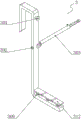
FIG. 1 is a schematic structural view of the present invention;
FIG. 2 is a schematic view of the positioning and connecting assembly of the present invention;
FIG. 3 is a schematic view of the mounting structure of the slide bar of the present invention;
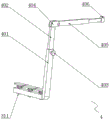
FIG. 4 is a schematic structural view of the shield assembly of the present invention;
reference numbers in the figures: 1. hanging a beam; 2. a hanging rod;
3. positioning the connecting assembly; 301. a first positioning screw; 302. connecting a solenoid; 303. a guide tube; 304. a slide bar; 305. positioning holes; 306. positioning a groove; 307. a pin; 308. a magnet; 309. a buffer spring; 310. a support plate; 311. a vertical rod; 312. a bearing plate; 313. an outer coil;
4. a guard assembly; 401. a fixed tube; 402. an extension rod; 403. a second positioning screw; 404. a clamping frame; 405. a telescopic rod; 406. and (7) clamping blocks.
Detailed Description
The preferred embodiments of the present invention will be described in conjunction with the accompanying drawings, and it will be understood that they are described herein for the purpose of illustration and explanation and not limitation.
Example (b): as shown in fig. 1-4, the present invention provides a stable steel suspended scaffold for engineering project construction, which comprises a hanging beam 1, hanging rods 2 are evenly hung and mounted on the outer side of the hanging beam 1, a positioning connection assembly 3 is arranged on the outer side of the hanging rod 2, the positioning connection assembly 3 comprises a first positioning screw 301, a connection screw pipe 302, a guide pipe 303, a sliding rod 304, a positioning hole 305, a positioning groove 306, a pin 307, a magnet 308, a buffer spring 309, a supporting plate 310, a vertical rod 311, a bearing plate 312 and an outer screw pipe 313;
the positioning connection assembly 3 comprises a first positioning screw 301, the first positioning screw 301 is installed at the top end of the hanging rod 2 in a penetrating mode, a connecting spiral pipe 302 is welded at one side of the middle of the hanging rod 2, a guide pipe 303 is hinged at the position of the same height as the connecting spiral pipe 302 at the other side of the middle of the hanging rod 2, the guide pipe 303 is connected with the hanging rod 2 through a hinge seat, the diameter of the guide pipe 303 is smaller than the thickness of the hanging beam 1 so as to facilitate installation of the guide pipe 303, a sliding rod 304 is installed inside the guide pipe 303 in a sliding mode, the longitudinal section of the guide pipe 303 is regular hexagon, the sliding rod 304 is matched with the guide pipe 303 so as to prevent the sliding rod 304 from rotating when being pulled, an outer spiral pipe 313 is sleeved at one end of the sliding rod 304 in a rotating mode, a positioning hole 305 is formed at one end, far away from a connection point, positioning grooves 306 are uniformly formed at one side, close to the positioning hole 305, pins 307 are installed inside the positioning hole 305 in a sliding mode, the positioning holes 306, the pins 307 are equal in diameter of the pins 305, the positioning holes 305, the pins 307, the positioning holes 306, the pins 307 and the pins 307 are equal to the magnets 308, the positioning hole 305 is matched with the pin 307, the top end of the pin 307 is provided with a pull ring, so that the pin 307 can be conveniently embedded into the positioning hole 305, and the bottom end of the pin 307 is bonded with a magnet 308;
the equidistant spot welding in peg 2 bottom is connected with buffer spring 309, and a plurality of buffer spring 309 top all spot welding connect the layer board 310, and the bottom surface of layer board 310 is in buffer spring 309 internal portion department welding has vertical pole 311, and the activity of vertical pole 311 bottom runs through peg 2 bottom, and bearing plate 312 has been placed on a plurality of layer boards 310 top.
The bottom end of the hanging rod 2, which is far away from the positioning connecting assembly 3, is provided with a protective assembly 4, and the protective assembly 4 comprises a fixed pipe 401, an extension rod 402, a second positioning screw 403, a clamping frame 404, an expansion rod 405 and a clamping block 406;
fixed pipe 401 welds in the bottom that the positioning connection subassembly 3 was kept away from to peg 2, the inside slidable mounting of fixed pipe 401 has extension rod 402, second positioning screw 403 is installed on fixed pipe 401 top, extension rod 402 top welding has joint frame 404, telescopic link 405 is installed through the pivot to the inside one end of joint frame 404, telescopic link 405 is kept away from junction one end welding and is had fixture block 406, joint frame 404 one end agrees with fixture block 406, fixed pipe 401 and extension rod 402 contact surface are smooth plane, be convenient for stimulate extension rod 402, aim at joint frame 404 embedding with fixture block 406.
The working principle and the using process of the utility model are as follows: the hanging rod 2 is sequentially hung on the position of a hanging beam 1 at equal intervals for preliminary fixing, the guide pipe 303 is rotated, the sliding rod 304 is pulled, the positioning hole 305 is aligned with the positioning groove 306, the pin 307 is installed, the magnet 308 adsorbs the iron sliding rod 304 for fixing and prevents dropping, the outer screwed pipe 313 and the connecting screwed pipe 302 are rotated for butt joint for connection, the connection is simple and convenient, the guide pipe 303 is rotated to be a movable structure, the butt joint position can be adjusted, the butt joint position is not easy to be misplaced, the distance between the hanging rods 2 is easy to adjust, the hanging rods 2 are fixed by rotating the first positioning screw 301, the stability of connection is ensured, the overall stability is improved, then the bearing plate 312 is laid, the bearing plate 312 is lapped on the top surface of the supporting plate 310, the bearing plate 312 is not directly contacted with the hanging rods 2, vibration between the bearing plate 312 and the hanging rods 2 is absorbed by the buffer spring 309, and therefore vibration transmitted to the joint of the hanging rods 2 when the top surface of the bearing plate 312 moves, the looseness of the connection part is prevented, and the safety is better;
the inside extension rod 402 of fixed pipe 401 of pulling, adjust the height of extension rod 402 in the fixed pipe 401, rotate extension rod 402 again and block 406 card go into the joint frame 404 in, extension rod 402 and joint frame 404 cooperation stand pipe 303 make up into the guardrail of scaffold frame both sides, improve the security, the accessible rotates telescopic link 405, opens the breach, makes things convenient for operating personnel to get into, and easy operation is convenient.
Finally, it should be noted that: although the present invention has been described in detail with reference to the foregoing embodiments, it will be apparent to those skilled in the art that changes may be made in the embodiments and/or equivalents thereof without departing from the spirit and scope of the utility model. Any modification, equivalent replacement, or improvement made within the spirit and principle of the present invention should be included in the protection scope of the present invention.