CN215326647U - Endless rope continuous traction winch multi-roadway transportation system - Google Patents
Endless rope continuous traction winch multi-roadway transportation system Download PDFInfo
- Publication number
- CN215326647U CN215326647U CN202121638299.5U CN202121638299U CN215326647U CN 215326647 U CN215326647 U CN 215326647U CN 202121638299 U CN202121638299 U CN 202121638299U CN 215326647 U CN215326647 U CN 215326647U
- Authority
- CN
- China
- Prior art keywords
- wheel
- rope
- guide wheel
- roadway
- main
- Prior art date
- Legal status (The legal status is an assumption and is not a legal conclusion. Google has not performed a legal analysis and makes no representation as to the accuracy of the status listed.)
- Active
Links
- 229910000831 Steel Inorganic materials 0.000 claims abstract description 23
- 239000010959 steel Substances 0.000 claims abstract description 23
- 239000000463 material Substances 0.000 abstract description 15
- 238000005065 mining Methods 0.000 description 2
- 238000006467 substitution reaction Methods 0.000 description 2
- 230000009286 beneficial effect Effects 0.000 description 1
- 239000003638 chemical reducing agent Substances 0.000 description 1
- 230000007547 defect Effects 0.000 description 1
- 238000000034 method Methods 0.000 description 1
Images


Landscapes
- Electric Cable Installation (AREA)
Abstract
The utility model discloses a multi-roadway transportation system of an endless rope continuous traction winch, which comprises a main roadway, a branch roadway after the main roadway turns, a winch and a tensioning device arranged on one side of the main roadway, a guide wheel set, a turning wheel set, a conventional wheel set, a steel wire rope and a shuttle car. According to the utility model, the steel wire rope can be connected with the front end and the rear end of the shuttle car through the guide wheel set, so that the shuttle car can freely advance forwards and backwards, the turning wheel set is added at the turning point of the roadway, and finally, the purpose of completing material transportation in multiple roadways by adopting one traction device is achieved. The utility model reduces the traction equipment and operators in multi-roadway transportation and improves the transportation efficiency.
Description
Technical Field
The utility model belongs to the technical field of mining engineering equipment, particularly relates to transportation equipment in a roadway, and particularly relates to a multi-roadway transportation system of an endless rope continuous traction winch.
Background
The endless rope continuous traction winch is powered by a motor, is driven by a speed reducer or a gearbox and a pair of involute cylindrical spur gears, and achieves the purpose of conveying heavy objects by means of friction force between a steel wire rope and a roller through rotation of the drum of the endless rope winch. The endless rope continuous traction winch transportation equipment is suitable for the direct transportation without transshipment of materials and equipment such as working face gate roads, mining area mountaineering and concentrated track roadways under the working conditions of long distance, large inclination angle, multiple slopes and large tonnage. The traditional material transportation mode is that an endless rope continuous traction winch can only transport materials back and forth in one roadway. When materials in the branch roadway are transported, a traction device needs to be added.
Disclosure of Invention
The utility model aims to provide a multi-roadway material transportation mode of an endless rope continuous traction winch, which overcomes the defect that one traction device needs to be added during material transportation in a branch roadway.
The purpose of the utility model is realized by the following technical scheme:
a multi-roadway transportation system of an endless rope continuous traction winch comprises a main roadway, a branch roadway after the main roadway turns, a winch and a tensioning device arranged on one side of the main roadway, a guide wheel set, a turning wheel set, a conventional wheel set, a steel wire rope and a shuttle car; the winch and tensioning device comprises: the system comprises a main machine of the endless rope winch, a hydraulic tensioning device connected behind the main machine of the endless rope winch, a tensioning tail pulley and a tensioning oblique pulley which are connected with the hydraulic tensioning device, and a heavy hammer tensioning device in front of the main machine of the endless rope winch; the guide wheel group includes: the device comprises two rope pressing guide wheels arranged in front of a heavy hammer tensioning device and 4 guide way guide wheels arranged in front of the two rope pressing guide wheels, wherein each rope pressing guide wheel comprises an inner side rope pressing guide wheel and an outer side rope pressing guide wheel; the 4 guide wheels are respectively a first guide wheel, a second guide wheel, a third guide wheel and a fourth guide wheel, the first guide wheel and the third guide wheel are arranged on the outer side of the main roadway, the second guide wheel and the fourth guide wheel are arranged on the main roadway, and the third guide wheel and the fourth guide wheel are positioned in front of the first guide wheel and the second guide wheel; the turning wheel group is formed by arranging and combining a plurality of turning wheels at a turning part connecting the main roadway and the branch roadway; the conventional wheel set includes: the main pressure rope wheel, the auxiliary pressure rope wheel, the rope supporting wheel, the main roadway tail wheel arranged at the tail end of the main roadway and the branch roadway tail wheel arranged at the tail end of the branch roadway are arranged on the main roadway; one end of the steel wire rope passes through a rope groove on a main machine of the endless rope winch and is wound for a plurality of circles, and then the steel wire rope passes through a heavy hammer tensioning device, an inner side rope pressing guide wheel, a first guide wheel, a second guide wheel, a rope supporting wheel, an auxiliary rope pressing wheel and a main roadway tail wheel and is fixed on the rear end of the shuttle car; the other end of the steel wire rope passes through a tensioning oblique wheel, passes through a rope groove on a main machine of the endless rope winch, is wound for a plurality of circles, then passes through a heavy hammer tensioning device, an outer side rope pressing guide wheel, a third guide wheel, a fourth guide wheel, a turning wheel, a tail wheel of a back branch roadway, is wound for a circle, passes through a rope supporting wheel and is fixed at the front end of the shuttle car through a main rope pressing wheel.
Furthermore, a rope pressing wheel and a rope supporting wheel are also arranged on the branch roadway.
Furthermore, the mode of the arrangement and combination of the turning wheels in the turning wheel group is as follows: every two transverse arrangement's of group turn wheel, multiunit turn wheel is along turning track longitudinal arrangement, and multiunit turn wheel passes through bottom plate fixed connection, and the bottom plate passes through the fix with screw on the tunnel.
Further, the multiple groups of turning wheels are at least 2 groups.
Further, a steel wire rope extending from the fourth guide wheel to the tail wheel direction of the branch roadway passes through the space between each two turning wheels; and the steel wire rope returning from the tail wheel of the branch roadway after being wound passes through the outer sides of the two transversely arranged turning wheels.
The utility model has the beneficial effects that:
1) according to the endless rope continuous traction winch system, the steel wire rope can be connected with the front end and the rear end of the shuttle car by adding the series of guide wheels, so that the shuttle car can freely move forwards and backwards, meanwhile, the turning wheel group is added at the turning point in the branch roadway, and finally, the material transportation in multiple roadways is completed by adopting one traction device.
2) The utility model reduces traction equipment, reduces operators and improves the transportation efficiency.
Drawings
Fig. 1 is a schematic view of the overall structure of the present invention.
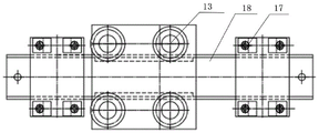
Fig. 2 is a schematic structural view (top view) of a turning wheel set.
FIG. 3 is a schematic view of a turning wheel set (side view)
Reference numerals:
1. an endless rope winch main machine; 2-1, pressing a rope guide wheel at the inner side; 2-2, pressing the rope guide pulley outside; 3. a hydraulic tensioning device; 4. a shuttle car; 5. a main rope pressing wheel; 6. a secondary pressure sheave; 7. a rope supporting wheel; 8-1, a tail wheel of the main roadway; 8-2, a tail wheel of the branch roadway; 9. a weight tensioner; 10. tensioning the tail pulley; 11. a wire rope; 12. tensioning a skew wheel; 13. a turning wheel; 14-1. a first guide wheel; 14-2. a second guide wheel; 14-3. a third guide wheel; 14-4. a fourth guide wheel; 15. a main roadway; 16. a branch roadway; 17. a screw; 18. a base plate; A. the rear end of the shuttle car; B. the front end of the shuttle car.
Detailed Description
Example 1
As shown in fig. 1, a multi-lane transportation system of an endless rope continuous traction winch comprises a main lane 15, a branch lane 16 after the main lane turns, a winch and a tensioning device arranged on one side of the main lane 15, a guide wheel set, a turning wheel set, a conventional wheel set, a steel wire rope 11 and a shuttle car 4;
the winch and tensioning device comprises: the system comprises an endless rope winch host 1, a hydraulic tensioning device 3 connected to the rear of the endless rope winch host 1, a tensioning tail pulley 10 and a tensioning skew pulley 12 connected with the hydraulic tensioning device 3, and a heavy hammer tensioning device 9 in front of the endless rope winch host 1;
the guide wheel group includes: the rope pressing guide wheels are arranged in front of the heavy hammer tensioning device 9, and the guide wheels are arranged in front of the two rope pressing guide wheels and comprise 4 guide way guide wheels, wherein each rope pressing guide wheel comprises an inner side rope pressing guide wheel 2-1 and an outer side rope pressing guide wheel 2-2; the 4 guide way guide wheels are respectively a first guide wheel 14-1, a second guide wheel 14-2, a third guide wheel 14-3 and a fourth guide wheel 14-4, the first guide wheel 14-1 and the third guide wheel 14-3 are arranged on the outer side of the main roadway 15, the second guide wheel 14-2 and the fourth guide wheel 14-4 are arranged on the main roadway 15, and the third guide wheel 14-3 and the fourth guide wheel 14-4 are positioned in front of the first guide wheel 14-1 and the second guide wheel 14-2;
the turning wheel group is formed by arranging and combining a plurality of turning wheels 13 at the turning part connecting a main roadway 15 and a branch roadway 16;
the conventional wheel set includes: a main pressure rope wheel 5, an auxiliary pressure rope wheel 6, a rope supporting wheel 7, a main roadway tail wheel 8-1 arranged at the tail end of the main roadway 15 and a branch roadway tail wheel 8-2 arranged at the tail end of a branch roadway 16 are arranged on the main roadway 15;
one end of a steel wire rope 11 passes through a rope groove on the endless rope winch main machine 1 and is wound for a plurality of circles, and then is fixed on the rear end A of the shuttle car 4 through a heavy hammer tensioning device 9, an inner side rope pressing guide wheel 2-1, a first guide wheel 14-1, a second guide wheel 14-2, a rope supporting wheel 7, an auxiliary rope pressing wheel 6 and a main roadway tail wheel 8-1; the other end of the steel wire rope 11 passes through a tensioning skew wheel 12, passes through a rope groove on the endless rope winch main machine 1, is wound for a plurality of circles, passes through a heavy hammer tensioning device 9, an outer side rope pressing guide wheel 2-2, a third guide wheel 14-3, a fourth guide wheel 14-4, a turning wheel 13, and then passes through a branch roadway tail wheel 8-2, and is wound for a circle, passes through a rope supporting wheel 7, and a main rope pressing wheel 5 and is fixed on the front end B of the shuttle car 4.
In this embodiment: the branch roadway 16 is also provided with a plurality of rope pressing wheels and rope supporting wheels.
As shown in fig. 2 and 3, the arrangement and combination of the turning wheels in the turning wheel set in this embodiment is as follows: and each group of the two transversely arranged turning wheels 13 is provided with a plurality of groups of turning wheels which are longitudinally arranged along a turning track, the plurality of groups of turning wheels are fixedly connected through a bottom plate 18, and the bottom plate 18 is fixed on a roadway through a screw 17. Any multiple groups can be selected according to actual working requirements, and at least 2 groups can be selected.
A steel wire rope 11 extending from the fourth guide wheel 14-4 to the tail wheel 8-2 direction of the branch roadway passes through between each two turning wheels 13; the steel wire rope 11 returning after being wound by the tail wheel 8-2 of the branch roadway passes through the outer sides of the two transversely arranged turning wheels 13. Can effectively ensure that the shuttle car smoothly passes through at the turning position.
Description of the working process: if a material mine car is hung at the end A of the shuttle car 4, a material mine car is hung at the end B of the shuttle car 4, when the endless rope winch host 1 rotates forwards, the steel wire rope 11 drives the shuttle car 4 to move forwards, and the material mine car hung at the end A of the shuttle car 4 and the material mine car hung at the end B of the shuttle car 4 also move forwards; when the endless rope winch main machine 1 rotates backwards, the steel wire rope 11 drives the shuttle car 4, the shuttle car 4 moves backwards, the material mine car hung at the end A of the shuttle car 4 moves backwards, and the material mine car hung at the end B of the shuttle car 4 also moves backwards. The material mine car can safely run at the roadway slope when being transported to the turning wheel 13.
The above description is only for the specific embodiments of the present invention, but the scope of the present invention is not limited thereto, and any person skilled in the art can easily conceive of the changes or substitutions within the technical scope of the present invention, and all the changes or substitutions should be covered within the scope of the present invention. Therefore, the protection scope of the present invention shall be subject to the protection scope of the appended claims.
Claims (5)
1. The utility model provides a many roadways transportation system of endless rope continuous traction winch which characterized in that: the device comprises a main roadway (15), a branch roadway (16) after the main roadway turns, a winch and a tensioning device arranged on one side of the main roadway (15), a guide wheel set, a turning wheel set, a conventional wheel set, a steel wire rope (11) and a shuttle car (4);
the winch and tensioning device comprises: the device comprises a main machine (1) of the endless rope winch, a hydraulic tensioning device (3) connected to the rear of the main machine (1) of the endless rope winch, a tensioning tail pulley (10) and a tensioning skew pulley (12) connected with the hydraulic tensioning device (3), and a heavy hammer tensioning device (9) in front of the main machine (1) of the endless rope winch;
the guide wheel group includes: the weight tensioning device comprises two rope pressing guide wheels arranged in front of the weight tensioning device (9) and 4 guide wheels arranged in front of the two rope pressing guide wheels, wherein each rope pressing guide wheel comprises an inner side rope pressing guide wheel (2-1) and an outer side rope pressing guide wheel (2-2); the 4 guide way guide wheels are respectively a first guide wheel (14-1), a second guide wheel (14-2), a third guide wheel (14-3) and a fourth guide wheel (14-4), the first guide wheel (14-1) and the third guide wheel (14-3) are arranged on the outer side of the main roadway (15), the second guide wheel (14-2) and the fourth guide wheel (14-4) are arranged on the main roadway (15), and the third guide wheel (14-3) and the fourth guide wheel (14-4) are positioned in front of the first guide wheel (14-1) and the second guide wheel (14-2);
the turning wheel group is formed by arranging and combining a plurality of turning wheels (13) at the turning part connecting the main roadway (15) and the branch roadway (16);
the conventional wheel set includes: a main pressure rope wheel (5), an auxiliary pressure rope wheel (6), a rope supporting wheel (7), a main tunnel tail wheel (8-1) arranged at the tail end of the main tunnel (15) and a branch tunnel tail wheel (8-2) arranged at the tail end of a branch tunnel (16) are arranged on the main tunnel (15);
one end of a steel wire rope (11) passes through a rope groove on a main machine (1) of the endless rope winch and is wound for a plurality of circles, and then the steel wire rope passes through a heavy hammer tensioning device (9), an inner side rope pressing guide wheel (2-1), a first guide wheel (14-1), a second guide wheel (14-2), a rope supporting wheel (7), an auxiliary rope pressing wheel (6) and a main roadway tail wheel (8-1) and is fixed on the rear end (A) of the shuttle car (4); the other end of the steel wire rope (11) passes through a tensioning skew wheel (12), passes through a rope groove on a main machine (1) of the endless rope winch, is wound for a plurality of circles, then passes through a heavy hammer tensioning device (9), an outer side rope pressing guide wheel (2-2), a third guide wheel (14-3), a fourth guide wheel (14-4), a turning wheel (13), a back pass branch roadway tail wheel (8-2), is wound for a circle, passes through a rope supporting wheel (7), and a main rope pressing wheel (5) is fixed on the front end (B) of the shuttle car (4).
2. The endless rope continuous traction winch multi-lane haulage system of claim 1, wherein: and a rope pressing wheel and a rope supporting wheel are also arranged on the branch roadway (16).
3. The endless rope continuous traction winch multi-lane haulage system of claim 1, wherein: the mode of the arrangement and combination of the turning wheels in the turning wheel group is as follows: the turning wheels (13) are transversely arranged in each group, the turning wheels are longitudinally arranged along a turning track, the turning wheels are fixedly connected through a bottom plate (18), and the bottom plate (18) is fixed on a roadway through screws (17).
4. The endless rope continuous traction winch multi-lane haulage system of claim 3, wherein: the multiple groups of turning wheels are at least 2 groups.
5. The endless rope continuous traction winch multi-lane haulage system of claim 3, wherein: a steel wire rope (11) extending from the fourth guide wheel (14-4) to the tail wheel (8-2) of the branch roadway passes through between each two turning wheels (13); the steel wire rope (11) which returns after being wound by the tail wheel (8-2) of the branch roadway passes through the outer sides of the two transversely arranged turning wheels (13).
Priority Applications (1)
| Application Number | Priority Date | Filing Date | Title |
|---|---|---|---|
| CN202121638299.5U CN215326647U (en) | 2021-07-19 | 2021-07-19 | Endless rope continuous traction winch multi-roadway transportation system |
Applications Claiming Priority (1)
| Application Number | Priority Date | Filing Date | Title |
|---|---|---|---|
| CN202121638299.5U CN215326647U (en) | 2021-07-19 | 2021-07-19 | Endless rope continuous traction winch multi-roadway transportation system |
Publications (1)
| Publication Number | Publication Date |
|---|---|
| CN215326647U true CN215326647U (en) | 2021-12-28 |
Family
ID=79568580
Family Applications (1)
| Application Number | Title | Priority Date | Filing Date |
|---|---|---|---|
| CN202121638299.5U Active CN215326647U (en) | 2021-07-19 | 2021-07-19 | Endless rope continuous traction winch multi-roadway transportation system |
Country Status (1)
| Country | Link |
|---|---|
| CN (1) | CN215326647U (en) |
Cited By (1)
| Publication number | Priority date | Publication date | Assignee | Title |
|---|---|---|---|---|
| CN116081209A (en) * | 2022-12-20 | 2023-05-09 | 山西中煤担水沟煤业有限公司 | A rail transport system capable of continuous transport of stepless rope winches |
-
2021
- 2021-07-19 CN CN202121638299.5U patent/CN215326647U/en active Active
Cited By (2)
| Publication number | Priority date | Publication date | Assignee | Title |
|---|---|---|---|---|
| CN116081209A (en) * | 2022-12-20 | 2023-05-09 | 山西中煤担水沟煤业有限公司 | A rail transport system capable of continuous transport of stepless rope winches |
| CN116081209B (en) * | 2022-12-20 | 2025-08-26 | 山西中煤担水沟煤业有限公司 | A rail transport system capable of realizing continuous transport with a stepless rope winch |
Similar Documents
| Publication | Publication Date | Title |
|---|---|---|
| CN101598018B (en) | Alpine bolter miner back affiliating travel type breaking and transhipping continuous transporting device | |
| CN110027867A (en) | One kind can overlap swing type speedy drivage system sealing-tape machine self-movable foot end | |
| CN211202013U (en) | A segment transport device suitable for large slope and fast transport | |
| CN201068346Y (en) | A scraper conveyor for loading | |
| CN102518008A (en) | Movable turnout platform used for shield tunnel | |
| CN112253158A (en) | Full-coal roadway cross shaft tunneling machine, control method and application | |
| CN102979521B (en) | Rocker-type transverse shearer | |
| CN107934443A (en) | The belt continuous haulage system that remote-controlled walking, tracking are turned | |
| CN202012369U (en) | Telescopic belt conveyer for fully-mechanized coal winning | |
| CN103935689A (en) | Belt conveyor capable of bending horizontally | |
| CN109707407B (en) | Mortar tank truck, auxiliary transfer device of mortar tank truck and tunnel construction transportation method | |
| CN203050701U (en) | Traction part with bridge-type structure for low-seam coal-mining machine | |
| CN202595586U (en) | Movable turnout platform used for shield tunnel | |
| CN103935688A (en) | Conveyor belt capable of bending horizontally | |
| CN105197626B (en) | A kind of material Loosen machine | |
| CN203097891U (en) | Rocker type transverse drum shearer | |
| CN112408225A (en) | Mining skip overhauls platform | |
| CN203699778U (en) | Double-roadway endless rope winch device | |
| CN103663231B (en) | Two tunnels endless rope winch device | |
| CN202165092U (en) | Split type automatic walking concrete pump | |
| CN206409240U (en) | A kind of track traffic bored tunnel electric railcar transports corollary system | |
| CN104860075B (en) | Chain stacking piles up equipment | |
| CN203189014U (en) | Vertical shearer with large inclination angle | |
| CN211418519U (en) | A mobile bridge loader | |
| CN210912407U (en) | Mining explosion-proof electric traction clamping rail toothed rail locomotive |
Legal Events
| Date | Code | Title | Description |
|---|---|---|---|
| GR01 | Patent grant | ||
| GR01 | Patent grant |