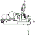
Oscillating grinding device
Technical Field
The utility model belongs to the technical field of workpiece polishing equipment, and particularly relates to a swing type polishing device.
Background
With the increasing demand for products, the improvement of the surface smoothness of the workpiece becomes a concern. Whether burrs protrude from the surface of the workpiece or welding seams protrude can influence partial assembled parts. At this time, special polishing equipment is needed to polish the workpiece. Traditional polishing is manual polishing, a polishing machine is held by an operator to polish a workpiece, the surface finish condition polished by the traditional polishing method depends on the experience of the operator, the surface finish of the polished product is uneven, the polishing part is not polished or polished more, the production efficiency is seriously influenced, and the cost is wasted. Later, special polishing equipment was available, which can polish a workpiece by fixing the workpiece through a special positioning mechanism, but the polishing equipment can only polish one surface of the workpiece, and other surfaces cannot be related, so that the universality is low.
Chinese patent 201310459883.8 discloses a swing type pipe end grinding machine, which comprises a base, a lifting rotary roller arranged at the front end of the base, a movable cart capable of moving on the base, a grinding device arranged on the movable cart, and a clamping mechanism arranged at the front end of the movable cart, wherein the grinding device comprises a feeding sliding table fixed on the movable cart, and an inner weld grinding mechanism and an outer weld grinding mechanism arranged on the feeding sliding table. The swing type pipe end grinding machine positions a pipe needing to be subjected to welding seam grinding through the lifting rotary roller and the clamping mechanism, the inner welding seam grinding mechanism and the outer welding seam grinding mechanism on the grinding device are driven to be located on the inner side and the outer side of the pipe respectively through the movement of the movable cart and the feeding sliding table, the pipe is subjected to copying grinding through the inner welding seam grinding mechanism and the outer welding seam grinding mechanism, the precision and the grinding efficiency of pipe end welding seams can be improved, and labor cost is saved. However, the utility model is used in the field of weld grinding devices and has an insufficient application range.
SUMMERY OF THE UTILITY MODEL
In order to solve the problems, the utility model provides a swing type polishing device which comprises a cylinder transmission mechanism, a workpiece positioning and clamping mechanism, a limiting mechanism and the like, can realize the positioning of a workpiece and the fixing of the workpiece in a polishing process, and can polish and swing the angle of the workpiece while polishing so as to realize multi-angle polishing. The utility model not only makes better use of the polishing equipment, but also improves the polishing quality and the production efficiency of the workpiece.
The utility model is implemented by the following technical scheme:
an oscillating sanding device comprising: backup pad, grinding part, swing mechanism polishes.
The supporting plate comprises a substrate a, a substrate b and a substrate c; the grinding part comprises a grinding machine and a grinding machine moving mechanism; the grinding swing mechanism comprises a clamping component and an angle adjusting component, wherein the clamping component comprises a workpiece holding mechanism and a workpiece positioning and clamping mechanism; the angle adjusting component comprises a limiting mechanism and a cylinder for swinging angle.
The sander moving mechanism is arranged on one side of the substrate a; the grinding machine is arranged above the grinding machine moving mechanism.
The substrate b is arranged on the other side of the substrate a; the base plate b be close to the part one side of polishing and install the support frame, support frame upper end be provided with the swing point A of the swing mechanism of polishing, the swing mechanism of polishing is connected with the support frame through swing point A.
The workpiece holding mechanism, the workpiece positioning and clamping mechanism and the limiting mechanism are arranged on the substrate c; the limiting mechanism is connected with the substrate b through two limiting guide rods capable of adjusting height. And a rotating point A is arranged between the workpiece holding mechanism and the workpiece positioning and clamping mechanism.
The cylinder for the swing angle comprises a cylinder body, a cylinder mounting plate, a cylinder mounting seat I, a cylinder mounting seat II and a cylinder telescopic guide rod.
The cylinder body is arranged on a cylinder mounting plate, and the cylinder mounting plate is connected to a cylinder mounting seat I through a rotating point B; the first cylinder mounting seat is connected with the substrate b; the cylinder telescopic guide rod is connected with the cylinder body and is connected to the second cylinder mounting seat through a rotating point C, and the second cylinder mounting seat is fixed on the substrate C.
The cylinder for the swing angle drives the whole clamping mechanism to rotate through the linkage of the cylinder telescopic guide rod, the rotating point A, the rotating point B and the rotating point C, and therefore the swing purpose is achieved.
The base plate a and the base plate b are installed in parallel, and the angle of the base plate c is adjusted along with the swinging of the polishing swinging mechanism.
The limiting mechanism and the oscillating angle cylinder are used for adjusting the rotating angle of the grinding workpiece.
The sander moving mechanism can move on the substrate a to push the sander to a sanding position for sanding.
When the swing angle is extended by the cylinder, the grinding inclination angle is up to 15 °.
When the swing angle is retracted by the air cylinder, the grinding inclination angle is up to 10 °.
The utility model has the following advantages:
1. the standard part adopts a universal standard part, is easy to purchase and has low cost;
2. the processing difficulty of the machined part is low, the use is simple and convenient, and no special skill requirement exists;
3. the swing polishing angle is changeable, the polishing machine can be used for polishing workpieces of various sizes, polishing compatibility is high, polishing cost is saved, polishing quality is guaranteed, and production efficiency is improved.
Drawings
FIG. 1 is a schematic view of the overall structure of a swing-type sanding device of the present invention;
FIG. 2 is a schematic side view of the swing grinding device of the present invention;
FIG. 3 is a schematic view of the swing limit position of the swing grinding apparatus of the present invention;
FIG. 4 is a schematic view of the swing limit position of the swing grinding apparatus of the present invention;
wherein: 1-grinding machine; 2, a workpiece holding mechanism; 3-turning point A; 4-a workpiece positioning and clamping mechanism; 5-a workpiece; 6-a limiting mechanism; 7-a cylinder body; 8-sander moving mechanism; 9-substrate c; 10-a cylinder mounting seat I; 11-a second cylinder mounting seat; 12-turning point B; 13-turning point C; 14-substrate a; 15-substrate b; 16-cylinder telescopic guide rod; 17-cylinder body mounting plate; 18-a guide bar for limiting; 19-support frame.
Detailed Description
The utility model will be further explained with reference to the drawings.
The oscillating grinding device is shown in figures 1-2:
the dresser moving mechanism 8 is mounted on one side of the substrate a 14;
the sander 1 is mounted above the sander moving mechanism 8;
the substrate b 15 is installed on the other side of the substrate a 14; the substrate a and the substrate b are mounted in parallel.
The base plate b 15 is provided with a supporting frame 19 close to one side of the grinding part, and the upper end of the supporting frame 19 is provided with a rotating point A3.
The workpiece holding mechanism 2, the workpiece positioning and clamping mechanism 4 and the limiting mechanism 6 are arranged on the substrate c.
The angle of the substrate c is adjusted along with the swinging of the polishing swinging mechanism.
The position-limiting mechanism 6 is connected to the base plate b 15 via two position-limiting guide rods 18 that can be adjusted in height.
A rotating point A is arranged between the workpiece holding mechanism 2 and the workpiece positioning and clamping mechanism 4 and is connected with the supporting frame 19 through the rotating point A.
The cylinder for the swing angle comprises a cylinder body 7, a cylinder mounting plate 17, a cylinder mounting seat I10, a cylinder mounting seat II 11 and a cylinder telescopic guide rod 16.
The cylinder body 7 is arranged on a cylinder mounting plate 17, and the cylinder mounting plate 17 is connected to a cylinder mounting seat I10 through a rotating point B; the first cylinder mounting seat 10 is connected with a base plate b 15; the cylinder telescopic guide rod 16 is connected with the cylinder body 7 and is connected to the second cylinder mounting seat 11 through a rotating point C13, and the second cylinder mounting seat 11 is fixed on the base plate C9.
The swing angle drives the whole clamping mechanism to rotate through the linkage of the cylinder telescopic guide rod 16, the rotating point A, the rotating point B and the rotating point C by using the cylinder, so that the swing purpose is achieved.
The workpiece 5 is placed on the workpiece holding mechanism 2 and is positioned and clamped through the mechanism, so that the workpiece 5 is kept fixed in the polishing process.
The dresser moving mechanism 8 can move on the substrate a 14 to push the dresser 1 to a dressing position for dressing.
As shown in fig. 3, when the swing angle is extended with the cylinder, the inclined angle of the sanding can reach 15 °; as shown in fig. 4, when the swing angle is retracted by the air cylinder, the inclined angle of the sanding may reach 10 °; the size of the grinding inclination angle can be realized by changing the stroke of the swing angle cylinder.
The swing type polishing mechanism is compact in structure and large in angle adjustment compatible range, different polishing swing angles can be realized by changing the stroke of the cylinder for the swing angle, compatibility can be realized for different workpieces, the polishing cost is greatly reduced, and the production efficiency is also improved.