CN215313864U - Raw materials sieving mechanism is used in extract processing - Google Patents
Raw materials sieving mechanism is used in extract processing Download PDFInfo
- Publication number
- CN215313864U CN215313864U CN202121950933.9U CN202121950933U CN215313864U CN 215313864 U CN215313864 U CN 215313864U CN 202121950933 U CN202121950933 U CN 202121950933U CN 215313864 U CN215313864 U CN 215313864U
- Authority
- CN
- China
- Prior art keywords
- box
- sliding
- box body
- screening
- raw materials
- Prior art date
- Legal status (The legal status is an assumption and is not a legal conclusion. Google has not performed a legal analysis and makes no representation as to the accuracy of the status listed.)
- Active
Links
- 239000002994 raw material Substances 0.000 title claims abstract description 31
- 238000007873 sieving Methods 0.000 title claims description 4
- 238000012216 screening Methods 0.000 claims abstract description 42
- 230000005540 biological transmission Effects 0.000 claims abstract description 10
- 238000003756 stirring Methods 0.000 claims abstract description 5
- 238000005096 rolling process Methods 0.000 claims description 18
- 238000009434 installation Methods 0.000 claims description 4
- 230000002146 bilateral effect Effects 0.000 claims 1
- 230000007547 defect Effects 0.000 abstract description 3
- 230000008878 coupling Effects 0.000 abstract 1
- 238000010168 coupling process Methods 0.000 abstract 1
- 238000005859 coupling reaction Methods 0.000 abstract 1
- 241001579180 Matthiola longipetala Species 0.000 description 1
- 230000009286 beneficial effect Effects 0.000 description 1
- 235000013399 edible fruits Nutrition 0.000 description 1
- 210000000416 exudates and transudate Anatomy 0.000 description 1
- 239000012467 final product Substances 0.000 description 1
- 230000005484 gravity Effects 0.000 description 1
- 238000000034 method Methods 0.000 description 1
- 230000004048 modification Effects 0.000 description 1
- 238000012986 modification Methods 0.000 description 1
- 239000003960 organic solvent Substances 0.000 description 1
- 230000000149 penetrating effect Effects 0.000 description 1
- 239000002904 solvent Substances 0.000 description 1
- XLYOFNOQVPJJNP-UHFFFAOYSA-N water Substances O XLYOFNOQVPJJNP-UHFFFAOYSA-N 0.000 description 1
Images

Landscapes
- Sampling And Sample Adjustment (AREA)
Abstract
The utility model discloses a raw material screening device for processing extractum, which comprises a box body with an opening on one side, wherein a box door is arranged at the opening position of the box body, sliding grooves are formed in the symmetrical inner side walls on the two sides of the box body, sliding blocks are connected in the sliding grooves in a sliding mode, one ends of the opposite sides of the two sliding blocks penetrate through corresponding sliding groove notches and extend outwards, screening plates are connected together, a U-shaped frame is arranged at the lower end of each screening plate, a collecting box is arranged at the inner bottom end of the U-shaped frame, a motor is arranged at the bottom of the inner box of the box body, and the output end of the motor is connected with a rotating disc through a coupling. The utility model overcomes the defects of the prior art, automatically screens the raw materials by the mutual matching of structures such as a chute, a sliding block, a screening plate, a motor, a rotating disc, a transmission column, a feeding pipe and the like, and automatically stirs the raw materials by the mutual matching of structures such as a reciprocating cylinder, a moving pipe, a moving rod, a brush and the like, thereby quickening the screening of the raw materials, saving the time and improving the working efficiency.
Description
Technical Field
The utility model relates to the field of extract processing, in particular to a raw material screening device for extract processing.
Background
The extract is prepared by extracting perfume plant tissue (such as flower, leaf branch, stem, bark, root, fruit, etc.) without exudate with organic solvent, and the final product contains no original solvent and water.
In the extract process of processing, often need filter the principle, at present, when current screening the raw materials, generally all manual the screening of manual work, it is great to consume the labour, and work efficiency is low.
SUMMERY OF THE UTILITY MODEL
Aiming at the defects of the prior art, the utility model provides a raw material screening device for processing extractum, which overcomes the defects of the prior art and aims to solve the problems that the existing raw material screening is generally carried out manually, the labor consumption is high, and the working efficiency is low.
In order to achieve the purpose, the utility model provides the following technical scheme: a raw material screening device for processing extractum comprises a box body with an opening on one side, wherein a box door is installed at the opening position of the box body, sliding grooves are formed in the symmetrical inner side walls of the two sides of the box body, sliding blocks are connected in the sliding grooves in a sliding mode, one ends of the opposite sides of the two sliding blocks penetrate through corresponding sliding groove notches and extend outwards, screening plates are connected with the sliding grooves and the sliding grooves together, a U-shaped frame is installed at the lower end of each screening plate, a collecting box is arranged at the inner bottom end of the U-shaped frame, a motor is installed at the inner box bottom of the box body, the output end of the motor is connected with a rotating disc through a coupler, a transmission column is hinged to the side wall of the other side of the rotating disc, the other end of the transmission column is hinged to the outer frame bottom of the U-shaped frame, a feeding pipe is installed at the upper end of the box body, and a shifting assembly is installed on the box body;
stir the subassembly including coming and going the cylinder, it installs on the lateral wall of box one side to come and go the cylinder, come and go cylinder piston end and run through the tank wall of box and inwards extend and be connected with the installation piece, come and go cylinder piston end sliding connection on the tank wall of box, the lower extreme of installation piece is connected with removes the pipe, it has the carriage release lever to remove intraductal sliding connection, the carriage release lever other end passes the mouth of pipe that removes the pipe and downwardly extending and be connected with the brush, the brush opposite side sets up the upper end at the screening board.
As a preferred technical scheme of the utility model, a sliding rod is fixedly connected in the sliding groove, the sliding rod penetrates through the sliding block, and the sliding block is connected to the sliding rod in a sliding manner.
As a preferable technical scheme of the utility model, one end of the sliding block, which is far away from the screening plate, is provided with a rolling groove, rolling balls are arranged in the rolling groove, the rolling balls penetrate through a notch of the rolling groove, and the rolling balls are connected with the bottom of the sliding groove in a rolling manner.
As a preferable technical scheme of the utility model, a supporting plate is connected to the outer side wall of one side of the box body, and the reciprocating cylinder is arranged on the supporting plate.
As a preferable technical scheme of the utility model, the upper end of the feeding pipe is provided with a hopper.
As a preferable technical solution of the present invention, a handle is mounted on an outer side wall of the door.
Compared with the prior art, the utility model has the beneficial effects that:
(1) according to the automatic screening machine, the raw materials are automatically screened through the mutual matching of the structures such as the sliding groove, the sliding block, the screening plate, the U-shaped frame, the collecting box, the motor, the rotating disc, the transmission column and the feeding pipe, so that the manual labor force is reduced, and the working efficiency is improved.
(2) The utility model automatically stirs the raw materials by the mutual matching of the structures of the reciprocating cylinder, the mounting block, the moving pipe, the moving rod, the brush and the like, accelerates the screening of the raw materials, saves the time and improves the working efficiency.
Drawings
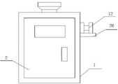
FIG. 1 is a schematic view of the overall structure of the present invention;
FIG. 2 is a front view of the present invention;
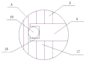
fig. 3 is an enlarged view of a portion a in fig. 1.
Description of reference numerals:
1. a box body; 2. a box door; 3. a chute; 4. a slider; 5. screening the plate; 6. a U-shaped frame; 7. a collection box; 8. a motor; 9. rotating the disc; 10. a drive post; 11. a feed pipe; 12. a reciprocating cylinder; 13. mounting blocks; 14. moving the tube; 15. a travel bar; 16. a brush; 17. a slide bar; 18. a rolling groove; 19. a ball bearing; 20. a support plate; 21. and (4) a hopper.
Detailed Description
The technical solutions in the embodiments of the present invention will be clearly and completely described below with reference to the drawings in the embodiments of the present invention, and it is obvious that the described embodiments are only a part of the embodiments of the present invention, and not all of the embodiments. All other embodiments, which can be derived by a person skilled in the art from the embodiments given herein without making any creative effort, shall fall within the protection scope of the present invention.
Referring to fig. 1-3, a raw material screening device for processing extractum, includes a box body 1 with an opening on one side, a box door 2 installed on the opening of the box body 1, a handle installed on the outer side wall of the box door 2 for opening the box door, sliding chutes 3 formed on the symmetrical inner side walls of the two sides of the box body 1, sliding blocks 4 connected in the sliding chutes 3, sliding rods 17 fixed in the sliding chutes 3, the sliding rods 17 penetrating the sliding blocks 4, the sliding blocks 4 connected in the sliding rods 17 for preventing the sliding blocks 4 from separating from the sliding chutes 3, rolling grooves 18 formed on the ends of the sliding blocks 4 far from the screening plates 5, rolling balls 19 arranged in the rolling grooves 18, the ball 19 passes through the notch of the rolling groove 18, the ball 19 is connected to the bottom of the sliding groove 3 in a rolling manner, the friction force between the sliding block 4 and the sliding groove 3 is reduced, the U-shaped frame 6 is installed at the lower end of the screening plate 5, the collecting box 7 is arranged at the inner bottom end of the U-shaped frame 6, the screened raw materials are collected, the motor 8 is installed at the inner bottom of the box body 1, the rotating disc 9 is driven to rotate by the motor 8, the output end of the motor 8 is connected with the rotating disc 9 through a coupler, the side wall at the other side of the rotating disc 9 is hinged with the transmission column 10, the other end of the transmission column 10 is hinged to the outer bottom of the U-shaped frame 6, the acting force is applied to the U-shaped frame 6 through the transmission column 10, the feeding pipe 11 is installed at the upper end of the box body 1, the shifting assembly is installed on the box body 1, the hopper 21 is installed at the upper end of the feeding pipe 11, the raw materials are conveniently placed into the box body 1 from the feeding pipe 11, and the rotating disc 9 is rotated by the motor 8, the indirect reciprocating motion that makes screening plate 5 vertical direction to, carry out the autofilter to the raw materials, reduce the hand labor power, improve work efficiency.
Specifically, referring to fig. 2, the toggle assembly includes a reciprocating cylinder 12, the reciprocating cylinder 12 is installed on an outer side wall of one side of the box body 1, a support plate 20 is connected to the outer side wall of one side of the box body 1, the reciprocating cylinder 12 is installed on the support plate 20 to prevent the reciprocating cylinder 12 from falling off the box body 1, a piston end of the reciprocating cylinder 12 penetrates through a wall of the box body 1 and extends inward and is connected with a mounting block 13, the mounting block 13 is driven to move by the reciprocating cylinder 12, the piston end of the reciprocating cylinder 12 is slidably connected to the wall of the box body 1, a moving pipe 14 is connected to a lower end of the mounting block 13, a moving rod 15 is slidably connected in the moving pipe 14, the other end of the moving rod 15 penetrates through a pipe orifice of the moving pipe 14 and extends downward and is connected with a brush 16, the other side of the brush 16 is installed at an upper end of the screening plate 5, the brush 16 toggles raw materials on the screening plate 5, the brush 16 is driven by the reciprocating cylinder 12 to horizontally and transversely reciprocate on the screening plate 5, stir the raw materials for the screening of raw materials, save time improves work efficiency.
The working principle is as follows: when the box is used, raw materials are put into the box body 1 from the feeding pipe 11, the raw materials enter the screening plate 5, the motor 8 is started, the motor 8 drives the rotating disc 9 to rotate, the rotating disc 9 rotates to generate acting force on the U-shaped frame 6 through the transmission column 10, the U-shaped frame 6 generates acting force on the screening plate 5, the screening plate 5 vertically reciprocates through the sliding block 4, the reciprocating cylinder 12 is started again, the reciprocating cylinder 12 drives the mounting block 13 to reciprocate horizontally and horizontally, the mounting block 13 moves to drive the moving pipe 14 to horizontally reciprocate, the moving pipe 14 drives the hairbrush 16 to horizontally and horizontally move through the moving rod 15, so that the raw materials on the screening plate 5 are stirred, and meanwhile, when the screening plate 5 vertically moves downwards, the hairbrush 16 and the moving rod 15 slide downwards under the acting force of gravity, the brush 16 is always attached to the sieving plate 5, and the sieved raw material enters the collecting box 7 to be collected.
Finally, it should be noted that: in the description of the present invention, it should be noted that the terms "vertical", "upper", "lower", "horizontal", and the like indicate orientations or positional relationships based on those shown in the drawings, and are only for convenience of describing the present invention and simplifying the description, but do not indicate or imply that the referred device or element must have a specific orientation, be constructed in a specific orientation, and be operated, and thus, should not be construed as limiting the present invention.
In the description of the present invention, it should also be noted that, unless otherwise explicitly specified or limited, the terms "disposed," "mounted," "connected," and "connected" are to be construed broadly and may, for example, be fixedly connected, detachably connected, or integrally connected; can be mechanically or electrically connected; they may be connected directly or indirectly through intervening media, or they may be interconnected between two elements. The specific meanings of the above terms in the present invention can be understood by those skilled in the art according to specific situations.
Although the present invention has been described in detail with reference to the foregoing embodiments, it will be apparent to those skilled in the art that changes may be made in the embodiments and/or equivalents thereof without departing from the spirit and scope of the utility model. Any modification, equivalent replacement, or improvement made within the spirit and principle of the present invention should be included in the protection scope of the present invention.
Claims (6)
1. The utility model provides a raw materials sieving mechanism is used in extract processing, includes that one side is open-ended box (1), its characterized in that: the box door is characterized in that the box door (2) is installed at the open position of the box body (1), sliding grooves (3) are formed in the inner side wall of the box body (1) in bilateral symmetry, sliding blocks (4) are connected in the sliding grooves (3) in a sliding mode, one ends of the opposite sides of the sliding blocks (4) penetrate through corresponding notches of the sliding grooves (3) and extend outwards and are connected with screening plates (5) together, a U-shaped frame (6) is installed at the lower end of the screening plates (5), a collecting box (7) is arranged at the inner bottom end of the U-shaped frame (6), a motor (8) is installed at the inner box bottom of the box body (1), the output end of the motor (8) is connected with a rotating disc (9) through a coupler, a transmission column (10) is hinged to the side wall of the other side of the rotating disc (9), the other end of the transmission column (10) is hinged to the outer box bottom of the U-shaped frame (6), an inlet pipe (11) is installed at the upper end of the box body (1), the box body (1) is provided with a shifting component;
stir the subassembly including round trip cylinder (12), round trip cylinder (12) are installed on the lateral wall of box (1) one side, round trip cylinder (12) piston end runs through the tank wall of box (1) and inwards extends and is connected with installation piece (13), round trip cylinder (12) piston end sliding connection is on the tank wall of box (1), the lower extreme of installation piece (13) is connected with removes pipe (14), it has carriage release lever (15) to remove intraductal sliding connection in pipe (14), the mouth of pipe that removes pipe (14) is passed to the carriage release lever (15) other end and downwards extends and is connected with brush (16), brush (16) opposite side sets up the upper end at screening plate (5).
2. The raw material screening device for processing the extractum, according to claim 1, is characterized in that: slide bar (17) are fixedly connected with in spout (3), slide bar (17) run through slider (4) and set up, and slider (4) sliding connection is on slide bar (17).
3. The raw material screening device for processing the extractum, according to claim 2, is characterized in that: the screening device is characterized in that a rolling groove (18) is formed in one end, far away from the screening plate (5), of the sliding block (4), rolling balls (19) are arranged in the rolling groove (18), the balls (19) penetrate through a notch of the rolling groove (18), and the balls (19) are connected to the bottom of the sliding groove (3) in a rolling mode.
4. The raw material screening device for processing the extractum, according to claim 1, is characterized in that: the outer side wall of one side of the box body (1) is connected with a supporting plate (20), and the reciprocating cylinder (12) is arranged on the supporting plate (20).
5. The raw material screening device for processing the extractum, according to claim 1, is characterized in that: the upper end of the feeding pipe (11) is provided with a hopper (21).
6. The raw material screening device for processing the extractum, according to claim 1, is characterized in that: and a handle is arranged on the outer side wall of the box door (2).
Priority Applications (1)
| Application Number | Priority Date | Filing Date | Title |
|---|---|---|---|
| CN202121950933.9U CN215313864U (en) | 2021-08-19 | 2021-08-19 | Raw materials sieving mechanism is used in extract processing |
Applications Claiming Priority (1)
| Application Number | Priority Date | Filing Date | Title |
|---|---|---|---|
| CN202121950933.9U CN215313864U (en) | 2021-08-19 | 2021-08-19 | Raw materials sieving mechanism is used in extract processing |
Publications (1)
| Publication Number | Publication Date |
|---|---|
| CN215313864U true CN215313864U (en) | 2021-12-28 |
Family
ID=79577777
Family Applications (1)
| Application Number | Title | Priority Date | Filing Date |
|---|---|---|---|
| CN202121950933.9U Active CN215313864U (en) | 2021-08-19 | 2021-08-19 | Raw materials sieving mechanism is used in extract processing |
Country Status (1)
| Country | Link |
|---|---|
| CN (1) | CN215313864U (en) |
-
2021
- 2021-08-19 CN CN202121950933.9U patent/CN215313864U/en active Active
Similar Documents
| Publication | Publication Date | Title |
|---|---|---|
| CN203972446U (en) | A kind of waste of vegetables and fruits is pulverized compression forming equipment | |
| CN221433249U (en) | Corn soaking device with sieving structure | |
| CN111672738A (en) | Building engineering is with novel screening sand device | |
| CN113019513B (en) | Energy-saving and environment-friendly concrete crushing and sorting equipment | |
| CN116746376B (en) | Hay cutting device | |
| CN118305078B (en) | A high-efficiency screening device for fertilizer production | |
| CN219965515U (en) | High-efficient construction waste screening plant | |
| CN220029526U (en) | Multi-station turning and milling device for steel mesh frame pull rod | |
| CN218190905U (en) | Feed production dust collector | |
| CN208373555U (en) | A kind of ore extraction screening installation | |
| CN215542628U (en) | A classified screening device for honeysuckle | |
| CN221581105U (en) | Powder filtering device | |
| CN217911580U (en) | Moxa preparation is with equipment of sieving | |
| CN222943917U (en) | Automatic screening and classification device for improved seed breeding | |
| CN219112200U (en) | Sand screening device for constructional engineering | |
| CN222585805U (en) | Filtering device and concentrated juice squeezing equipment | |
| CN219581099U (en) | Agricultural seed screening installation | |
| CN218309261U (en) | Tea screening and impurity removing machine | |
| CN220277570U (en) | Sand screening device | |
| CN222287393U (en) | Refractory material raw material crushing processing device | |
| CN217663607U (en) | Tea-oil camellia seed reducing mechanism is used in tea-oil camellia processing | |
| CN220004279U (en) | Mud cake reducing mechanism for municipal sewage treatment | |
| CN224234491U (en) | Cynoglossus semilaevis offspring seed classifying and screening equipment | |
| CN218963237U (en) | Raw material screening mechanism for covering agent processing | |
| CN220900937U (en) | Screening machine of bio-organic fertilizer |
Legal Events
| Date | Code | Title | Description |
|---|---|---|---|
| GR01 | Patent grant | ||
| GR01 | Patent grant |