Multilayer agitating unit for industrial chemicals
Technical Field
The utility model relates to a chemical industry raw materials stirring technical field specifically is a multilayer agitating unit for chemical industry raw materials.
Background
The chemical raw materials can be generally divided into two types of organic chemical raw materials and inorganic chemical raw materials, and the products are three-state: the solid-liquid gas, wherein the most processing devices required in the production process are stirring devices, materials are stirred, mixed, blended, homogenized and the like, the stainless steel stirring tank can be standardized and humanized in design structure and configuration according to the requirements of the production process, and the stirring tank can realize feeding control, discharging control, stirring control, other manual and automatic control and the like in the stirring process.
However, the stirring paddle of the stirring device for the existing chemical raw materials mostly adopts the bottom stirring mode to stir, and most of the stirring paddles only have one layer of stirring paddle, so that the stirring effect is poor, and especially when the chemical raw materials with higher viscosity are stirred, the stirring paddle can not stir the upper layer of raw materials.
Therefore, it is necessary to provide a multi-layer stirring apparatus for chemical raw materials to solve the above problems.
SUMMERY OF THE UTILITY MODEL
An object of the utility model is to provide a multilayer agitating unit for industrial chemicals to propose in solving above-mentioned background art and do not possess the multilayer stirring and the problem that the inner wall condenses appears.
In order to achieve the above object, the utility model provides a following technical scheme: a multilayer stirring device for chemical raw materials comprises a tank body and a transmission component, wherein the inside of the tank body is fixedly connected with a stirring component, the stirring assembly comprises a scraping assembly, the scraping assembly comprises a scraping plate, the top of the scraping plate is fixedly connected with a cross rod, the right side of the cross rod is fixedly connected with a first snap ring group, the interior of the scraping component is fixedly connected with a layering component, the layered assembly comprises a first stirring paddle, the left side of the first stirring paddle is fixedly connected with a second clamping ring group, a second stirring paddle is arranged above the first stirring paddle, a third stirring paddle is arranged above the second stirring paddle, a connecting rod is fixedly connected between the second stirring paddle and the third stirring paddle, a propeller blade is arranged between the second clamping ring groups, the top of the tank body is fixedly connected with an end cover through a fastener, and the top of the end cover is fixedly connected with a transmission assembly.
Further, the fixed journal stirrup of outer wall fixedly connected with of the jar body, and be provided with four groups, and evenly distributed is at the outer wall of the jar body, the discharge gate has been seted up to the bottom of the jar body, the top of end cover is provided with the feed inlet.
Further, the bottom of scraper blade is circular-arc, and through snap ring fixed connection at the outer wall of main shaft, the top of first stirring rake is provided with the lug, the bottom of horizontal pole is seted up flutedly, the scraper blade is the plug-in connection with the horizontal pole, and adopts the bolt to fix.
Further, first stirring rake is the slope form, the size of second stirring rake is the two-thirds of third stirring rake, fixedly connected with connecting rod between first stirring rake and the second stirring rake, the connecting rod is the slope form, propeller blade is provided with two sections altogether.
Further, the transmission assembly comprises a motor, a speed reducer is fixedly connected to the lower portion of the motor, a rotating shaft is arranged at the bottom of the speed reducer, a main shaft is fixedly connected to the lower portion of the rotating shaft through a coupler, and a supporting seat is fixedly connected to the bottom of the speed reducer.
Further, the supporting seat is of an L-shaped structure and is fixedly connected to the upper surface of the end cover through bolts, the ball bearing is fixedly connected to the outer portion of the main shaft and is arranged at the center of the end cover, and the bearing seat is fixedly connected to the bottom of the main shaft.
Compared with the prior art, the beneficial effects of the utility model are that:
1. the utility model discloses a improve traditional individual layer agitating unit, be three-layer stirring rake under the middle and middle of it sets up and stir jointly, and then can realize the even stirring of the inside raw materials of device, and the propeller blade that sets up through the cooperation can realize upwards stirring of raw materials, further accelerates the flow of raw materials for it stirs the mixture.
2. The utility model discloses a be provided with the scraper blade in the inside of device, through the drive of main shaft, can drive the scraper blade and rotate, further can be through the rotation of scraper blade, realize the stirring of striking off to the device inner wall, avoid the heating that its inner wall stored the raw materials to condense.
Drawings
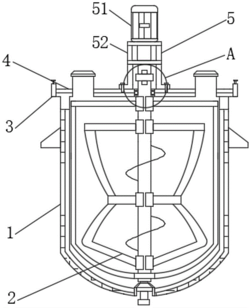
Fig. 1 is a schematic view of a front view cross-sectional structure of the present invention;
fig. 2 is an enlarged schematic view of the structure a in fig. 1 according to the present invention;
fig. 3 is a schematic view of the structure of the present invention;
fig. 4 is a schematic view of the stirring assembly of the present invention.
In the figure: 1. a tank body; 2. a stirring assembly; 21. a scraping assembly; 211. a squeegee; 212. a cross bar; 213. a first snap ring set; 22. a layered component; 221. a first stirring paddle; 222. a second snap ring set; 223. a second stirring paddle; 224. a third stirring paddle; 225. a connecting rod; 226. a propeller blade; 3. a fastener; 4. an end cap; 5. a transmission assembly; 51. a motor; 52. a speed reducer; 53. a rotating shaft; 54. a coupling; 55. a main shaft; 56. and (4) supporting the base.
Detailed Description
The technical solutions in the embodiments of the present invention will be described clearly and completely with reference to the accompanying drawings in the embodiments of the present invention, and it is obvious that the described embodiments are only some embodiments of the present invention, not all embodiments. Based on the embodiments in the present invention, all other embodiments obtained by a person skilled in the art without creative work belong to the protection scope of the present invention.
Referring to fig. 1-4, the present invention provides an embodiment:
the utility model provides a multilayer agitating unit for industrial chemicals, including jar body 1 and drive assembly 5, the inside fixedly connected with stirring subassembly 2 of jar body 1, stirring subassembly 2 is including striking off subassembly 21, setting through this structure, can realize stirring jar internal wall raw materials of body 1, further the heating that raw materials appears in the inner wall that can effectual surface jar body 1 condenses, it includes scraper blade 211 to strike off subassembly 21, the top fixedly connected with horizontal pole 212 of scraper blade 211, the first snap ring group 213 of right side fixedly connected with of horizontal pole 212, strike off subassembly 21's inside fixedly connected with layering subassembly 22, setting through this structure, can realize the layering stirring to inside raw materials.
The layered assembly 22 comprises a first stirring paddle 221, a second clamping ring group 222 is fixedly connected to the left side of the first stirring paddle 221, a second stirring paddle 223 is arranged above the first stirring paddle 221, a third stirring paddle 224 is arranged above the second stirring paddle 223, a connecting rod 225 is fixedly connected between the second stirring paddle 223 and the third stirring paddle 224, a spiral blade 226 is arranged between the second clamping ring group 222, a fastening piece 3 is fixedly connected to the top of the tank body 1 through an end cover 4, and a transmission assembly 5 is fixedly connected to the top of the end cover 4.
The fixed journal stirrup of outer wall fixedly connected with of jar body 1, and be provided with four groups, and evenly distributed is at the outer wall of jar body 1 for jar body 1's the fixed use of support, the discharge gate has been seted up to jar body 1's bottom, and end cover 4's top is provided with the feed inlet, realizes the reinforced processing of processing raw materials.
The bottom of scraper blade 211 is circular-arcly, and outer wall at main shaft 55 through snap ring fixed connection, the top of first stirring rake 221 is provided with the lug, the bottom of horizontal pole 212 is seted up flutedly, scraper blade 211 is the plug-in connection with horizontal pole 212, and adopt the bolt to fix, structure setting through scraper blade 211, the inner wall that can laminate jar body 1 rotates, further rotation through main shaft 55 drives it and rotates, further can realize its striking off to jar body 1 inner wall, avoid when carrying out industrial chemicals add, the condensation of raw materials appears.
First stirring rake 221 is the slope form, and the size of second stirring rake 223 is the two-thirds of third stirring rake 224, fixedly connected with connecting rod 225 between first stirring rake 221 and the second stirring rake 223, and connecting rod 225 is the slope form, and propeller blade 226 is provided with two sections altogether, and through propeller blade 226's setting, can rotate through it, drives jar 1 inside industrial chemicals of body and rises, further accelerates industrial chemicals's flow to it stirs the mixture.
The transmission assembly 5 comprises a motor 51, a speed reducer 52 is fixedly connected to the lower portion of the motor 51, a rotating shaft 53 is arranged at the bottom of the speed reducer 52, a main shaft 55 is fixedly connected to the lower portion of the rotating shaft 53 through a coupler 54, a supporting seat 56 is fixedly connected to the bottom of the speed reducer 52, the speed reducer 52 is started through the motor 51, the rotation of the motor 51 can be further reduced through the speed reducer 52, the rotation of the rotating shaft 53 is achieved, the main shaft 55 is further driven to rotate through the rotation of the rotating shaft 53, and then the stirring assembly 2 can be driven to rotate.
Supporting seat 56 is L shape structure, supporting seat 56 passes through bolt fixed connection at the upper surface of end cover 4, the outside fixedly connected with ball bearing of main shaft 55, and set up the center at end cover 4, the bottom fixedly connected with bearing frame of main shaft 55, setting through supporting seat 56, it is fixed to play the support to speed reducer 52 and motor 51, further improve the stability of its connection, the ball bearing setting through main shaft 55 upper and lower both ends simultaneously, can play and reduce main shaft 55 pivoted frictional force, improve its rotation efficiency, increase its pivoted stability simultaneously.
The working principle is as follows: when the utility model is used, firstly, the chemical raw materials to be processed are added in the tank body 1, further, the motor 51 is started, the rotation of the motor 51 can be reduced through the speed reducer 52, the rotation of the rotating shaft 53 is realized, the main shaft 55 is further driven to rotate through the rotation of the rotating shaft 53, and the stirring component 2 can be further driven to rotate, the rotation of the layering component 22 can be further realized, the connecting rod 225 is further driven to rotate through the rotation of the first stirring paddle 221, the second stirring paddle 223 and the third stirring paddle 224, and the stirring treatment of the chemical raw materials can be further realized, meanwhile, the stirring treatment of the chemical raw materials can be realized by the arrangement of the propeller blades 226, the ascending flowing of the raw materials can be realized, the stirring and mixing of the chemical raw materials can be accelerated, and the scraping work of the inner wall of the tank body 1 can be realized through the rotation of the first stirring paddle 221, can realize through its rotation that it rotates at jar 1 inner wall, and then avoid jar inner wall adhesion raw materials of body 1 to chemical industry raw materials's condensation appears in the effectual inner wall of avoiding jar body 1.
It is obvious to a person skilled in the art that the invention is not restricted to details of the above-described exemplary embodiments, but that it can be implemented in other specific forms without departing from the spirit or essential characteristics of the invention. The present embodiments are therefore to be considered in all respects as illustrative and not restrictive, the scope of the invention being indicated by the appended claims rather than by the foregoing description, and all changes which come within the meaning and range of equivalency of the claims are therefore intended to be embraced therein. Any reference sign in a claim should not be construed as limiting the claim concerned.