CN215232958U - Dust device with energy-saving function for civil construction - Google Patents
Dust device with energy-saving function for civil construction Download PDFInfo
- Publication number
- CN215232958U CN215232958U CN202120009135.XU CN202120009135U CN215232958U CN 215232958 U CN215232958 U CN 215232958U CN 202120009135 U CN202120009135 U CN 202120009135U CN 215232958 U CN215232958 U CN 215232958U
- Authority
- CN
- China
- Prior art keywords
- support column
- box
- fixed mounting
- wall
- fixedly connected
- Prior art date
- Legal status (The legal status is an assumption and is not a legal conclusion. Google has not performed a legal analysis and makes no representation as to the accuracy of the status listed.)
- Expired - Fee Related
Links
Images


Classifications
-
- Y—GENERAL TAGGING OF NEW TECHNOLOGICAL DEVELOPMENTS; GENERAL TAGGING OF CROSS-SECTIONAL TECHNOLOGIES SPANNING OVER SEVERAL SECTIONS OF THE IPC; TECHNICAL SUBJECTS COVERED BY FORMER USPC CROSS-REFERENCE ART COLLECTIONS [XRACs] AND DIGESTS
- Y02—TECHNOLOGIES OR APPLICATIONS FOR MITIGATION OR ADAPTATION AGAINST CLIMATE CHANGE
- Y02P—CLIMATE CHANGE MITIGATION TECHNOLOGIES IN THE PRODUCTION OR PROCESSING OF GOODS
- Y02P70/00—Climate change mitigation technologies in the production process for final industrial or consumer products
- Y02P70/10—Greenhouse gas [GHG] capture, material saving, heat recovery or other energy efficient measures, e.g. motor control, characterised by manufacturing processes, e.g. for rolling metal or metal working
Landscapes
- Nozzles (AREA)
Abstract
The utility model discloses a soil and timber construction is with dust device that has energy-conserving function relates to the dust device field, to the problem of the low and extravagant a large amount of water resources of current dust device dust fall efficiency, now proposes following scheme, and it includes the box, box bottom inner wall fixed mounting has the storage water tank, just storage water tank bottom inner wall rotates installs the support column, the support column top runs through the box along its length direction, just the support column is close to box top inner wall one end circumference lateral wall fixedly connected with backup pad, backup pad top fixed mounting has the mount pad, just mount pad top fixed mounting has the biax motor. The utility model discloses novel structure, and the device not only are equipped with drive arrangement, make the support column drive collection wind tunnel slowly rotate through the biax motor, reach comprehensive spraying dust fall's effect, and be equipped with pendulous device, play the effect that makes collection wind tunnel luffing motion.
Description
Technical Field
The utility model relates to a dust device field especially relates to a dust device with energy-conserving function for civil engineering.
Background
In civil engineering construction, a large amount of building materials such as cement and concrete are used, so that a lot of dust exists in the air and on the ground on the construction site of civil engineering construction, and workers have great influence on their own health if working in such environment for a long time.
The water pipe is held to the building site to the manual work to the present mostly, reaches the effect of dust fall through this kind of method, and this kind of method has not only wasted a large amount of water resources, and dust fall efficiency is not high moreover, has wasted a large amount of labours simultaneously, has brought pressure for workman's work. Therefore, in order to solve the above problems, we propose a dust fall device with an energy saving function for civil engineering.
SUMMERY OF THE UTILITY MODEL
The utility model provides a pair of dust device with energy-conserving function for civil engineering has solved the problem of the low and extravagant a large amount of water resources of current dust device dust fall efficiency.
In order to achieve the above purpose, the utility model adopts the following technical scheme:
a dust fall device with an energy-saving function for civil construction comprises a box body, wherein a water storage tank is fixedly arranged on the inner wall of the bottom end of the box body, a support column is rotatably arranged on the inner wall of the bottom end of the water storage tank, the top end of the support column penetrates through the box body along the length direction of the support column, a support plate is fixedly connected with the circumferential side wall of one end, close to the inner wall of the top end of the box body, of the support column, a mounting seat is fixedly mounted at the top end of the support plate, a double-shaft motor is fixedly mounted at the top end of the mounting seat, a driving device is mounted between one section of output shaft, close to the support column, of the double-shaft motor and the support column, a support box is fixedly mounted at the top end of the support plate, a swinging device is arranged between the output shaft and the support box, the top end of the support column is fixedly provided with a groove, supporting columns with the same structure are rotatably mounted on the inner walls on the two sides of the groove, and an air collecting barrel is fixedly mounted between the two supporting columns, just air-collecting duct one end inner wall fixed mounting has the air-blower, the support column is close to storage water tank one end circumference lateral wall fixed mounting has the mounting panel, just mounting panel top fixed mounting has the suction pump, set up in the support column and accomodate the groove, just the suction pump is close to support column one side fixed mounting has the water pipe, the water pipe is kept away from suction pump one end and is located air-collecting duct in its length direction and with air-collecting duct top inner wall fixed connection, just air-blower one side fixed mounting is kept away from to the water pipe has the atomizer that the structure is the same and be the distribution of rectangular array, the auto-lock universal wheel that the structure is the same is all installed in box bottom four corners.
Preferably, drive arrangement includes drive gear and driven gear the support column is close to the fixed driven gear that has cup jointed of box top inner wall one end circumference lateral wall, just the double-shaft motor is close to the fixed drive gear that has cup jointed of support column one end output shaft, drive gear and driven gear meshing.
Preferably, pendulous device includes hydraulic telescoping rod, frame, tooth piece and loose gear, slidable mounting has the frame in the support box, just the frame top slides and runs through support box and fixed mounting has hydraulic telescoping rod, hydraulic telescoping rod loose axle top is articulated with air collecting duct circumference lateral wall, just the equal fixed mounting of frame both sides inner wall has the structure the same and is the tooth piece that the rectangle array distributes, the biax motor is kept away from support column one end output shaft and is run through support box and fixed cover and has been connect loose gear, just loose gear and tooth piece meshing, just fixedly connected with spring between frame bottom and the support box bottom inner wall.
Preferably, the same slider of structure is all fixedly mounted to the frame both sides, just support the box both sides inner wall and seted up the spout with slider assorted, the loose gear is incomplete gear.
Preferably, the top end of the supporting plate is fixedly connected with a supporting block, the top end of the water storage tank is provided with a movable groove matched with the supporting block, and the movable groove is annular.
Preferably, air collecting cylinder circumference lateral wall fixed mounting has solar cell panel, just storage water tank top fixed mounting has the battery, battery input and solar cell panel fixed connection, just battery output and double-shaft motor fixed connection.
Preferably, box one side fixedly connected with PLC controller, just PLC controller input and battery fixed connection, PLC controller output and double-shaft motor fixed connection, just storage water tank one side fixedly connected with inlet tube, storage water tank one end is kept away from to the inlet tube and is run through the box.
The utility model has the advantages that:
1. through being equipped with drive arrangement, utilize the biax motor to make the support column drive the slow rotation of air-collecting duct, reach the effect of all-round dust fall, and be equipped with pendulous device, the biax motor drives loose gear and rotates, loose gear for incomplete gear and with the meshing of frame both sides inner wall tooth piece, play the effect that makes frame area air-collecting duct luffing motion, reach the effect of high-efficient dust fall.
2. Through being equipped with solar cell panel and battery cooperation, reach the effect of self power supply, save the resource, through biax motor drive pendulous device and drive arrangement, luffing motion when can making the device reach the pivoted reaches high-efficient dust fall's effect, has reduced staff's the amount of labour.
To sum up, the device novel structure not only is equipped with drive arrangement, makes the support column drive collection dryer slowly rotate through the biax motor, reaches comprehensive spraying dust fall's effect, and is equipped with pendulous device, plays the effect that makes collection dryer luffing motion, and is equipped with solar cell panel, can reach the effect of self power supply and save the resource.
Drawings
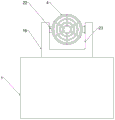
Fig. 1 is a schematic structural view of the present invention;
FIG. 2 is an enlarged view of A in FIG. 1 according to the present invention;
FIG. 3 is a side cross-sectional view of the support box and frame of the present invention;
fig. 4 is a side view of the present invention.
Reference numbers in the figures: 1. a box body; 2. a water storage tank; 3. a PLC controller; 4. an air collecting cylinder; 5. a blower; 6. a solar panel; 7. a hydraulic telescopic rod; 8. a frame; 9. a support box; 10. a support plate; 11. a support block; 12. a movable groove; 13. a double-shaft motor; 14. mounting a plate; 15. a water pump; 16. a support pillar; 17. a receiving groove; 18. a driven gear; 19. a drive gear; 20. a tooth block; 21. a movable gear; 22. a pillar; 23. a groove; 24. and (4) a storage battery.
Detailed Description
The technical solutions in the embodiments of the present invention will be described clearly and completely with reference to the accompanying drawings in the embodiments of the present invention, and it is obvious that the described embodiments are only some embodiments of the present invention, not all embodiments.
Referring to fig. 1-4, a dust-settling device with energy-saving function for civil construction comprises a box body 1, a water storage tank 2 is fixedly arranged on the inner wall of the bottom end of the box body 1, a support column 16 is rotatably arranged on the inner wall of the bottom end of the water storage tank 2, the top end of the support column 16 penetrates through the box body 1 along the length direction, a support plate 10 is fixedly connected with the circumferential side wall of one end of the support column 16 close to the inner wall of the top end of the box body 1, a mounting seat is fixedly arranged on the top end of the support plate 10, a double-shaft motor 13 is fixedly arranged on the top end of the mounting seat, a driving device is arranged between one section of an output shaft of the double-shaft motor 13 close to the support column 16 and the support column 16, a support box 9 is fixedly arranged on the top end of the support column 13 far away from the support column 16, a groove 23 is fixedly arranged on the top end of the support column 16, and supports 22 with the same structure are rotatably arranged on the inner walls of both sides of the groove 23, fixed mounting has wind-collecting cylinder 4 between two pillars 22, and 4 one end inner wall fixed mounting of wind-collecting cylinder has air-blower 5, support column 16 is close to 2 one end circumference lateral walls fixed mounting of storage water tank has mounting panel 14, and 14 top fixed mounting of mounting panel has suction pump 15, it accomodates groove 17 to have seted up in the support column 16, and suction pump 15 is close to 16 one side fixed mounting of support column has the water pipe, the water pipe is kept away from 15 one end of suction pump and is located wind-collecting cylinder 4 along its length direction and with 4 top inner wall fixed connection of wind-collecting cylinder, and 5 one side fixed mounting of air-blower is kept away from to the water pipe has the atomizer that the structure is the same and be the distribution of rectangle array, the auto-lock universal wheel that the structure is the same is all installed in 1 bottom four corners of box.
The driving device comprises a driving gear 19 and a driven gear 18, a supporting column 16 of the driving gear 19 is fixedly sleeved on the circumferential side wall of one end close to the inner wall of the top end of the box body 1, a driven gear 18 is fixedly sleeved on the circumferential side wall of one end close to the supporting column 16 of the double-shaft motor 13, an output shaft of one end close to the supporting column 16 of the double-shaft motor 13 is fixedly sleeved on the driving gear 19, the driving gear 19 is meshed with the driven gear 18, the swinging device comprises a hydraulic telescopic rod 7, a frame 8, a tooth block 20 and a movable gear 21, the frame 8 is slidably installed in the supporting box 9, the top end of the frame 8 slidably penetrates through the supporting box 9 and is fixedly provided with the hydraulic telescopic rod 7, the top end of a movable shaft of the hydraulic telescopic rod 7 is hinged with the circumferential side wall of the wind collecting barrel 4, the tooth blocks 20 which are identical in structure and are distributed in a rectangular array are fixedly installed on the inner walls of two sides of the frame 8, the output shaft of one end, which is far away from the supporting column 16 of the double-shaft motor 13, penetrates through the supporting box 9 and is fixedly sleeved with the movable gear 21, and is meshed with the tooth block 20, a spring is fixedly connected between the bottom end of the frame 8 and the inner wall of the bottom end of the supporting box 9, sliders with the same structure are fixedly arranged on both sides of the frame 8, sliding grooves matched with the sliders are formed in the inner walls of both sides of the supporting box 9, the movable gear 21 is an incomplete gear, the top end of the supporting plate 10 is fixedly connected with a supporting block 11, a movable groove 12 matched with the supporting block 11 is formed in the top end of the water storage tank 2, the movable groove 12 is annular, a solar cell panel 6 is fixedly arranged on the circumferential side wall of the wind collecting cylinder 4, a storage battery 24 is fixedly arranged at the top end of the water storage tank 2, the input end of the storage battery 24 is fixedly connected with the solar cell panel 6, the output end of the storage battery 24 is fixedly connected with the double-shaft motor 13, a PLC controller 3 is fixedly connected with one side of the box body 1, the input end of the PLC controller 3 is fixedly connected with the storage battery 24, and the output end of the PLC controller 3 is fixedly connected with the double-shaft motor 13, and one side of the water storage tank 2 is fixedly connected with a water inlet pipe, and one end of the water inlet pipe, which is far away from the water storage tank 2, penetrates through the tank body 1.
The working principle is as follows: when the device is refitted and used, a worker and a team can push the device to a proper position through the self-locking universal wheel, the PLC 3 controls the hydraulic telescopic rod 7 to drive the wind collecting barrel 4 to rise and adjust to a proper angle, the double-shaft motor 13 is started, the double-shaft motor 13 drives the driving gear 19 to rotate, the driving gear 19 drives the driven gear 18 to rotate, so that the supporting column 16 drives the wind collecting barrel 4 to rotate slowly, meanwhile, the double-shaft motor 13 drives the movable gear 21 to rotate, the movable gear 21 is an incomplete gear, the effect of driving the frame 8 to drive the hydraulic telescopic rod 7 to swing up and down is achieved, the wind collecting barrel 4 swings up and down, the worker controls and drives the air blower 5 and the water pump 15 through the PLC 3, the water in the water storage tank 2 is pumped into the water pipe through the water pump 15 and is sprayed out through the atomizing nozzle, under the effect of blowing the air blower 5, the effect of dust fall is achieved, the solar cell panel 6 is installed at the top end of the wind collecting barrel 4, the double-shaft motor 13 can be driven to rotate through solar power generation, resources are saved, the driving device and the swinging device are driven through the double-shaft motor 13, the dust falling device can swing up and down while rotating, and the effect of comprehensive dust falling is achieved.
The above, only be the concrete implementation of the preferred embodiment of the present invention, but the protection scope of the present invention is not limited thereto, and any person skilled in the art is in the technical scope of the present invention, according to the technical solution of the present invention and the utility model, the concept of which is equivalent to replace or change, should be covered within the protection scope of the present invention.
Claims (7)
1. The utility model provides a dust device with energy-conserving function for civil construction, includes box (1), its characterized in that, box (1) bottom inner wall fixed mounting has storage water tank (2), just storage water tank (2) bottom inner wall rotates and installs support column (16), support column (16) top runs through box (1) along its length direction, just support column (16) are close to box (1) top inner wall one end circumference lateral wall fixedly connected with backup pad (10), backup pad (10) top fixed mounting has the mount pad, and mount pad top fixed mounting has biax motor (13), biax motor (13) are close to and install drive arrangement between support column (16) one section output shaft of support column (16) and support column (16), and backup pad (10) top fixed mounting has support box (9), biax motor (13) keep away from and are equipped with pendulous device between support column (16) one end output shaft and support box (9), the utility model discloses a water pump, including support column (16), recess (23), fixed mounting have air collection cylinder (4) between support column (22), just recess (23) both sides inner wall all rotates and installs the same pillar of structure (22), two fixed mounting has air-blower (5) in the air collection cylinder (4), support column (16) are close to storage water tank (2) one end circumference lateral wall fixed mounting has mounting panel (14), just mounting panel (14) top fixed mounting has suction pump (15), set up in support column (16) and accomodate groove (17), just suction pump (15) are close to support column (16) one side fixed mounting has the water pipe, the water pipe is kept away from suction pump (15) one end and is located air collection cylinder (4) along its length direction and with air-blower (4) top inner wall fixed connection, just air-blower (5) one side fixed mounting is kept away from to the water pipe has the atomizer that the structure is the same and is the rectangular array distributes, four corners of the bottom end of the box body (1) are provided with self-locking universal wheels with the same structure.
2. The dust falling device with the energy saving function for civil engineering according to claim 1, characterized in that the driving device comprises a driving gear (19) and a driven gear (18), the driven gear (18) is fixedly sleeved on the circumferential side wall of one end of the support column (16) close to the inner wall of the top end of the box body (1), the driving gear (19) is fixedly sleeved on the output shaft of one end of the double-shaft motor (13) close to the support column (16), and the driving gear (19) is meshed with the driven gear (18).
3. The dust falling device with the energy saving function for civil engineering according to claim 1, wherein the swinging device comprises a hydraulic telescopic rod (7), a frame (8), a toothed block (20) and a movable gear (21), the frame (8) is slidably mounted in the supporting box (9), the top end of the frame (8) slidably penetrates through the supporting box (9) and is fixedly provided with the hydraulic telescopic rod (7), the top end of a movable shaft of the hydraulic telescopic rod (7) is hinged with the circumferential side wall of the air collecting barrel (4), the toothed blocks (20) which have the same structure and are distributed in a rectangular array are fixedly mounted on the inner walls of two sides of the frame (8), an output shaft of the double-shaft motor (13) far away from the supporting column (16) penetrates through the supporting box (9) and is fixedly sleeved with the movable gear (21), and the movable gear (21) is meshed with the toothed block (20), and a spring is fixedly connected between the bottom end of the frame (8) and the inner wall of the bottom end of the supporting box (9).
4. The dust falling device with the energy saving function for civil engineering according to claim 3, characterized in that the frame (8) is fixedly mounted with sliders with the same structure on both sides, and the supporting box (9) is provided with sliding grooves on both inner walls of both sides thereof, and the loose gear (21) is an incomplete gear.
5. The dust falling device with the energy saving function for civil construction according to claim 1, characterized in that the top end of the support plate (10) is fixedly connected with a support block (11), and the top end of the water storage tank (2) is provided with a movable groove (12) matched with the support block (11), the movable groove (12) being annular.
6. The dust falling device with the energy saving function for civil engineering according to claim 1, characterized in that solar cell panel (6) is fixedly installed on the circumferential side wall of the air collecting duct (4), a storage battery (24) is fixedly installed at the top end of the water storage tank (2), the input end of the storage battery (24) is fixedly connected with the solar cell panel (6), and the output end of the storage battery (24) is fixedly connected with the double-shaft motor (13).
7. The dust falling device with the energy saving function for civil engineering according to claim 1, characterized in that a PLC controller (3) is fixedly connected to one side of the box body (1), the input end of the PLC controller (3) is fixedly connected with the storage battery (24), the output end of the PLC controller (3) is fixedly connected with the double-shaft motor (13), a water inlet pipe is fixedly connected to one side of the water storage tank (2), and one end of the water inlet pipe, which is far away from the water storage tank (2), penetrates through the box body (1).
Priority Applications (1)
| Application Number | Priority Date | Filing Date | Title |
|---|---|---|---|
| CN202120009135.XU CN215232958U (en) | 2021-01-05 | 2021-01-05 | Dust device with energy-saving function for civil construction |
Applications Claiming Priority (1)
| Application Number | Priority Date | Filing Date | Title |
|---|---|---|---|
| CN202120009135.XU CN215232958U (en) | 2021-01-05 | 2021-01-05 | Dust device with energy-saving function for civil construction |
Publications (1)
| Publication Number | Publication Date |
|---|---|
| CN215232958U true CN215232958U (en) | 2021-12-21 |
Family
ID=79489323
Family Applications (1)
| Application Number | Title | Priority Date | Filing Date |
|---|---|---|---|
| CN202120009135.XU Expired - Fee Related CN215232958U (en) | 2021-01-05 | 2021-01-05 | Dust device with energy-saving function for civil construction |
Country Status (1)
| Country | Link |
|---|---|
| CN (1) | CN215232958U (en) |
-
2021
- 2021-01-05 CN CN202120009135.XU patent/CN215232958U/en not_active Expired - Fee Related
Similar Documents
| Publication | Publication Date | Title |
|---|---|---|
| CN205253699U (en) | Solar panel cleaning robot | |
| CN107379256A (en) | A kind of construction concrete central mix plant | |
| CN105724193A (en) | A solar power vehicle for an electric reel sprinkler irrigation machine | |
| CN111794166A (en) | Dust fall machine for hydraulic engineering construction site | |
| CN209155397U (en) | High spray efficiency tower crane spray system | |
| CN107975243A (en) | A kind of construction robot | |
| CN215191265U (en) | Ground cleaning device for building engineering | |
| CN211612054U (en) | Environment-friendly dust device for construction | |
| CN210993504U (en) | Environment-friendly dust collector for construction | |
| CN211818122U (en) | Brick body spray set for construction | |
| CN214345221U (en) | Dust suppression device used in green building construction | |
| CN213077884U (en) | Air environmental protection dust device for outdoor construction | |
| CN214862136U (en) | Dust collector for building engineering | |
| CN207980726U (en) | A kind of live dust-extraction unit of construction | |
| CN209848572U (en) | Environmental protection dust collecting equipment of building engineering construction | |
| CN221095777U (en) | Plastering frame for plastering mortar | |
| CN206693578U (en) | A kind of wall surface spraying work car | |
| CN205567338U (en) | Electronic reel sprinkling machine's solar electric source car | |
| CN221345419U (en) | Road dust cleaning device for municipal building | |
| CN224260386U (en) | Mine dust treatment equipment | |
| CN220696241U (en) | Bridge floor sprays firing equipment | |
| CN213823961U (en) | Dust collector for construction with regulatory function | |
| CN211116088U (en) | Fog gun machine that tunnel construction used | |
| CN213132448U (en) | Energy-saving type engineering ground dust treatment device | |
| CN219964352U (en) | Dust suppression device for civil engineering construction |
Legal Events
| Date | Code | Title | Description |
|---|---|---|---|
| GR01 | Patent grant | ||
| GR01 | Patent grant | ||
| CF01 | Termination of patent right due to non-payment of annual fee |
Granted publication date: 20211221 |
|
| CF01 | Termination of patent right due to non-payment of annual fee |