CN215207766U - Multi-core automatic point finding and wire arranging device - Google Patents
Multi-core automatic point finding and wire arranging device Download PDFInfo
- Publication number
- CN215207766U CN215207766U CN202120881329.9U CN202120881329U CN215207766U CN 215207766 U CN215207766 U CN 215207766U CN 202120881329 U CN202120881329 U CN 202120881329U CN 215207766 U CN215207766 U CN 215207766U
- Authority
- CN
- China
- Prior art keywords
- fixed
- servo motor
- arranging device
- guide frame
- support
- Prior art date
- Legal status (The legal status is an assumption and is not a legal conclusion. Google has not performed a legal analysis and makes no representation as to the accuracy of the status listed.)
- Active
Links
Images


Abstract
The utility model discloses an automatic winding displacement device of looking for of multicore, including base, support and connecting plate, the bottom mounting of base has the supporting legs, the both sides on base top all are fixed with the support, one side of support is fixed with second servo motor, the bottom of mounting panel is provided with guide structure, guide structure includes guide frame, locating plate, mounting groove, regulation pole and clamping ring, the guide frame is fixed in the bottom of mounting panel, the inside top of guide frame is fixed with the locating plate. The utility model discloses a be provided with guide structure, adjust the pole and pass through screw-thread fit and install in the mounting groove, along with operating personnel rotates the regulation pole, can drive the clamping ring on top through the screw-threaded cooperation and remove to this can adjust the interval between clamping ring and the top locating plate according to the thickness of cable, the semi-annular design of clamping ring is also convenient for carry on spacingly to the cable more, has realized the spacing guidance quality of this winding displacement device to the cable.
Description
Technical Field
The utility model relates to a winding displacement device technical field, in particular to automatic line winding device of looking for of multicore.
Background
The winding and arranging device is equipment for winding and arranging the electric wires and cables and winding the electric wires and cables on the winding roller, and the equipment is convenient for people to store and wind the cables, so that the working efficiency of operators is greatly improved;
chinese patent No. CN208054610U, announcement day 2018, 11.06 discloses an automatic wire arranging device, including the portal frame, the electric cabinet, wire arranging device and cycloid device, the electric cabinet is arranged in the portal frame side, wire arranging device arranges in on the portal frame, cycloid device is connected with the portal frame through the connecting plate, cycloid device includes X to mobile device, Y to mobile device, Z to mobile device, range unit and swing wheelset, swing wheelset carries out the cycloid, range unit surveys the distance, when the distance that surveys is less than the scope of settlement, control box control cycloid device moves in X, Y, Z three directions, such operation of recirculation carries out the winding displacement. The utility model has the advantages that: the cable arranging device has the advantages that the structure is compact, each circle of cables is tightly arranged after winding, the cable arranging quality is improved, the automation degree is high, the cables are orderly arranged on the cable arranging disc, the strength of the whole device is enhanced by the portal frame, and the cable arranging device can adapt to cable arranging with larger wire diameter;
the cable arranging device has the following defects that the cable arranging device is inconvenient to adjust and limit according to cables with different sizes, and is inconvenient to operate a plurality of groups of cables, so that the cable arranging device needs to be improved.
SUMMERY OF THE UTILITY MODEL
Technical problem to be solved
The utility model aims at providing an automatic line arranging device of looking for of multicore for solve current line arranging device and be not convenient for carry out the defect of spacing direction to the cable.
(II) contents of utility model
In order to solve the technical problem, the utility model provides a following technical scheme: the utility model provides an automatic winding displacement device of looking for of multicore, includes base, support and connecting plate, the bottom mounting of base has the supporting legs, the both sides on base top all are fixed with the support, one side of support is fixed with second servo motor, the opposite side that second servo motor one side extended to the support, receive the line roller is installed to one side of second servo motor, the top of support is provided with moving mechanism, moving mechanism's bottom is provided with the connecting plate, the bottom of connecting plate is provided with adjusts the structure, the bottom of adjusting the structure is provided with the mounting panel, the bottom of mounting panel is provided with guide structure, guide structure includes guide frame, locating plate, mounting groove, regulation pole and clamping ring, the guide frame is fixed in the bottom of mounting panel, the inside top of guide frame is fixed with the locating plate.
Preferably, the moving mechanism comprises a cross frame, a first servo motor, a rotating shaft and a moving block, the cross frame is fixed at the top end of the support, the first servo motor is installed on one side of the cross frame, one side of the first servo motor extends into the cross frame, the rotating shaft is installed on one side of the first servo motor, one side of the rotating shaft is movably connected with one side of the inside of the cross frame, the moving block is arranged on the surface of the rotating shaft, and the bottom end of the moving block extends to the bottom end of the cross frame.
Preferably, adjust the structure and include outer tube, interior pole and locating pin, the outer tube is fixed in the bottom of connecting plate, the internally mounted of outer tube has interior pole, interior pole bottom extends to the bottom of outer tube, the bottom of outer tube one side is provided with the locating pin.
Preferably, the inner diameter of the outer pipe is larger than the outer diameter of the inner rod, and the outer pipe and the inner rod form a telescopic structure.
Preferably, the bottom of guide frame is provided with the mounting groove, the inside of mounting groove is run through there is the regulation pole, the top movable mounting of adjusting the pole has the clamping ring.
Preferably, the mounting groove is provided with three groups in the bottom of guide frame, three groups the mounting groove is equidistant distribution.
Preferably, the inside of mounting groove is provided with the internal thread, the surface of adjusting the pole is provided with the external screw thread.
(III) advantageous effects
The utility model provides a pair of automatic line arranging device of looking for of multicore, its advantage lies in: the cable arranging device is provided with the guide structure, the adjusting rod is installed in the installation groove in a threaded fit mode, the adjusting rod is rotated along with an operator, the pressing ring at the top end can be driven to move in a threaded fit mode, so that the distance between the pressing ring and the upper positioning plate can be adjusted according to the thickness of a cable, the cable is more conveniently limited due to the semi-annular design of the pressing ring, and the limiting and guiding performance of the cable arranging device on the cable is achieved;
the moving mechanism is arranged, so that the rotating shaft can be driven to rotate along with the start of an operator by the first servo motor, and the moving block on the surface of the rotating shaft can move left and right through threaded fit, so that the guide frame below the rotating shaft can be driven to move left and right, the arrangement of cables can be more uniform, and the arrangement of the cables of the cable arranging device is realized;
through being provided with the regulation structure, interior pole is installed and is formed a structure of telescopic in the outer tube to this operating personnel can extend or shorten interior pole as required, adjusts the height of below guide frame with this, so that the better winding of cable is on receiving the line roller, when adjusting suitable amount height, operating personnel only need twist and move the locating pin, to the inner pole fix can, realized the controllability of this winding displacement device guide frame height.
Drawings
In order to more clearly illustrate the embodiments of the present invention or the technical solutions in the prior art, the drawings needed to be used in the description of the embodiments or the prior art will be briefly described below, and it is obvious that the drawings in the following description are some embodiments of the present invention, and for those skilled in the art, other drawings can be obtained according to these drawings without creative efforts.
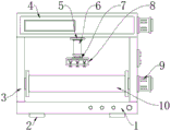
Fig. 1 is a schematic front view of the present invention;
fig. 2 is a schematic three-dimensional structure of the present invention;
fig. 3 is a schematic view of a front sectional structure of the moving mechanism of the present invention;
fig. 4 is a schematic view of the front cross-sectional structure of the adjusting structure of the present invention;
fig. 5 is a schematic view of the front cross-section structure of the guiding structure of the present invention.
In the figure: 1. a base; 2. supporting legs; 3. a support; 4. a moving mechanism; 401. a cross frame; 402. a first servo motor; 403. a rotating shaft; 404. a moving block; 5. a connecting plate; 6. an adjustment structure; 601. an outer tube; 602. an inner rod; 603. positioning pins; 7. mounting a plate; 8. a guide structure; 801. a guide frame; 802. positioning a plate; 803. mounting grooves; 804. adjusting a rod; 805. pressing a ring; 9. a second servo motor; 10. and (5) taking up the wire roller.
Detailed Description
In order to make the objects, technical solutions and advantages of the embodiments of the present invention clearer, the embodiments of the present invention will be clearly and completely described below with reference to the accompanying drawings in the embodiments of the present invention, and it is obvious that the described embodiments are some, but not all, embodiments of the present invention. Based on the embodiments of the present invention, all other embodiments obtained by a person of ordinary skill in the art without creative efforts belong to the protection scope of the present invention.
In the description of the present invention, it is to be noted that, unless otherwise explicitly specified or limited, the terms "mounted," "connected," and "connected" are to be construed broadly, and may be, for example, fixedly connected, detachably connected, or integrally connected; can be mechanically or electrically connected; they may be connected directly or indirectly through intervening media, or they may be interconnected between two elements. The specific meaning of the above terms in the present invention can be understood in specific cases to those skilled in the art.
Referring to fig. 1-5, the present invention provides an embodiment: a multi-core automatic point finding and wire arranging device comprises a base 1, a support 3 and a connecting plate 5, wherein a supporting leg 2 is fixed at the bottom end of the base 1, the support 3 is fixed at both sides of the top end of the base 1, a second servo motor 9 is fixed at one side of the support 3, the type of the second servo motor 9 can be HD-EA-370, one side of the second servo motor 9 extends to the other side of the support 3, a wire receiving roller 10 is installed at one side of the second servo motor 9, a moving mechanism 4 is arranged at the top end of the support 3, the moving mechanism 4 comprises a transverse frame 401, a first servo motor 402, a rotating shaft 403 and a moving block 404, the transverse frame 401 is fixed at the top end of the support 3, a first servo motor 402 is installed at one side of the transverse frame 401, the type of the first servo motor 402 can be R107R77, one side of the first servo motor 402 extends to the inside of the transverse frame 401, and a rotating shaft 403 is installed at one side of the first servo motor 402, one side of the rotating shaft 403 is movably connected with one side inside the cross frame 401, a moving block 404 is arranged on the surface of the rotating shaft 403, and the bottom end of the moving block 404 extends to the bottom end of the cross frame 401;
specifically, as shown in fig. 1 and 3, when the mechanism is used, a cross frame 401 is erected at the top end of a support 3 and located above a wire take-up roller 10, a rotating shaft 403 is installed inside the cross frame 401, the rotating shaft 403 is driven by a first servo motor 402, the rotating shaft 403 can be driven to rotate as an operator starts the first servo motor 402, a moving block 404 on the surface of the rotating shaft 403 can be moved left and right through threaded fit, so that a lower guide frame 801 can be driven to move left and right, and the arrangement of cables can be more uniform;
the bottom end of the moving mechanism 4 is provided with a connecting plate 5, the bottom end of the connecting plate 5 is provided with an adjusting structure 6, the adjusting structure 6 comprises an outer tube 601, an inner rod 602 and a positioning pin 603, the outer tube 601 is fixed at the bottom end of the connecting plate 5, the inner rod 602 is installed inside the outer tube 601, the bottom end of the inner rod 602 extends to the bottom end of the outer tube 601, the positioning pin 603 is arranged at the bottom end of one side of the outer tube 601, the inner diameter of the outer tube 601 is larger than the outer diameter of the inner rod 602, and the outer tube 601 and the inner rod 602 form a telescopic structure;
specifically, as shown in fig. 1 and 4, when the structure is used, the inner diameter of the outer tube 601 is larger than the outer diameter of the inner rod 602, and the inner rod 602 is installed in the outer tube 601 to form a telescopic structure, so that an operator can extend or shorten the inner rod 602 as required to adjust the height of the lower guide frame 801, so that a cable can be better wound on the cable take-up roller 10, and when the height is adjusted to a proper amount, the operator only needs to screw the positioning pin 603 to fix the inner rod 602;
the bottom end of the adjusting structure 6 is provided with a mounting plate 7, the bottom end of the mounting plate 7 is provided with a guide structure 8, the guide structure 8 comprises a guide frame 801, a positioning plate 802, mounting grooves 803, adjusting rods 804 and a pressing ring 805, the guide frame 801 is fixed at the bottom end of the mounting plate 7, the positioning plate 802 is fixed at the top end inside the guide frame 801, the mounting groove 803 is formed at the bottom end of the guide frame 801, the adjusting rods 804 penetrate through the inside of the mounting groove 803, the pressing ring 805 is movably mounted at the top end of the adjusting rods 804, three groups of mounting grooves 803 are arranged at the bottom end of the guide frame 801, the three groups of mounting grooves 803 are distributed at equal intervals, internal threads are arranged inside the mounting groove 803, and external threads are arranged on the surface of the adjusting rods 804;
specifically, as shown in fig. 1 and 5, when the structure is used, the guide frame 801 is mounted at the bottom of the mounting plate 7 and suspended above the wire take-up roller 10, a plurality of sets of mounting grooves 803 are machined at the bottom of the guide frame 801, internal threads are machined inside the mounting grooves 803, the adjusting rod 804 is mounted in the mounting grooves 803 in a threaded fit manner, the adjusting rod 804 is rotated by an operator, the pressing ring 805 at the top end can be driven to move in a threaded fit manner, so that the distance between the pressing ring 805 and the upper positioning plate 802 can be adjusted according to the thickness of a cable, and the cable is more conveniently limited due to the semi-annular design of the pressing ring 805.
The working principle is as follows: when the wire arranging device is used, firstly, the wire arranging device is externally connected with a power supply, an operator firstly loosens the positioning pin 603 on the outer tube 601, adjusts the height of the lower guide frame 801 by adjusting the inner rod 602, adjusts the guide frame 801 to a proper height for use, and screws the positioning pin 603 to fix after the adjustment is completed;
secondly, an operator penetrates a cable through the guide frame 801, one end of the cable is wound on the cable take-up roller 10, when the cable penetrates through the guide frame 801, the operator can limit and guide the cable through the adjusting rod 804 at the bottom of the guide frame 801 and the pressing ring 805 at the top of the adjusting rod 804 to prevent the cable from shaking and deviating, and the guide frame 801 is provided with a plurality of groups of adjusting rods 804 and pressing rings 805 to simultaneously perform cable arrangement on the plurality of groups of cables;
finally, an operator starts the second servo motor 9 to enable the take-up roller 10 to rotate for taking up wires, at this time, the operator can start the first servo motor 402, the first servo motor 402 can drive the rotating shaft 403 to rotate, the moving block 404 on the surface of the rotating shaft 403 can be fixed through thread matching, and therefore the guide frame 801 below the rotating shaft moves left and right above the take-up roller 10, the arrangement of the cables is more uniform and tidy, and the whole using process of the cable arranging device is finally completed.
In the description of the present invention, it is to be noted that, unless otherwise explicitly specified or limited, the terms "mounted," "connected," and "connected" are to be construed broadly, and may be, for example, fixedly connected, detachably connected, or integrally connected; can be mechanically or electrically connected; they may be connected directly or indirectly through intervening media, or they may be interconnected between two elements. The specific meaning of the above terms in the present invention can be understood in specific cases to those skilled in the art.
The above-described embodiments of the apparatus are merely illustrative, and the units described as separate parts may or may not be physically separate, and parts displayed as units may or may not be physical units, may be located in one place, or may be distributed on a plurality of network units. Some or all of the modules may be selected according to actual needs to achieve the purpose of the solution of the present embodiment. One of ordinary skill in the art can understand and implement it without inventive effort.
Finally, it should be noted that: the above embodiments are only used to illustrate the technical solution of the present invention, and not to limit it; although the present invention has been described in detail with reference to the foregoing embodiments, it should be understood by those skilled in the art that: the technical solutions described in the foregoing embodiments may still be modified, or some technical features may be equivalently replaced; such modifications and substitutions do not depart from the spirit and scope of the present invention in its corresponding aspects.
Claims (7)
1. The utility model provides an automatic line arranging device of finding point of multicore, includes base (1), support (3) and connecting plate (5), its characterized in that: the bottom end of the base (1) is fixed with a supporting leg (2), and two sides of the top end of the base (1) are fixed with a bracket (3);
a second servo motor (9) is fixed on one side of the support (3), one side of the second servo motor (9) extends to the other side of the support (3), a wire take-up roller (10) is installed on one side of the second servo motor (9), a moving mechanism (4) is arranged at the top end of the support (3), and a connecting plate (5) is arranged at the bottom end of the moving mechanism (4);
the bottom of connecting plate (5) is provided with adjusts structure (6), the bottom of adjusting structure (6) is provided with mounting panel (7), the bottom of mounting panel (7) is provided with guide structure (8), guide structure (8) are including guide frame (801), locating plate (802), mounting groove (803), regulation pole (804) and clamping ring (805), the bottom of mounting panel (7) is fixed in guide frame (801), the inside top of guide frame (801) is fixed with locating plate (802).
2. The multi-core automatic point finding and wire arranging device of claim 1, wherein: the moving mechanism (4) comprises a transverse frame (401), a first servo motor (402), a rotating shaft (403) and a moving block (404), the transverse frame (401) is fixed to the top end of the support (3), the first servo motor (402) is installed on one side of the transverse frame (401), one side of the first servo motor (402) extends to the inside of the transverse frame (401), the rotating shaft (403) is installed on one side of the first servo motor (402), one side of the rotating shaft (403) is movably connected with one side of the inside of the transverse frame (401), the moving block (404) is arranged on the surface of the rotating shaft (403), and the bottom end of the moving block (404) extends to the bottom end of the transverse frame (401).
3. The multi-core automatic point finding and wire arranging device of claim 1, wherein: adjust structure (6) and include outer tube (601), interior pole (602) and locating pin (603), the bottom of connecting plate (5) is fixed in outer tube (601), the internally mounted of outer tube (601) has interior pole (602), the bottom of interior pole (602) bottom extends to outer tube (601), the bottom of outer tube (601) one side is provided with locating pin (603).
4. The multi-core automatic point finding and wire arranging device of claim 3, wherein: the inner diameter of the outer pipe (601) is larger than the outer diameter of the inner rod (602), and the outer pipe (601) and the inner rod (602) form a telescopic structure.
5. The multi-core automatic point finding and wire arranging device of claim 1, wherein: the bottom of guide frame (801) is provided with mounting groove (803), the inside of mounting groove (803) is run through and is had regulation pole (804), the top movable mounting of adjusting pole (804) has clamping ring (805).
6. The multi-core automatic point finding and wire arranging device of claim 1, wherein: the mounting grooves (803) are provided with three groups at the bottom end of the guide frame (801), and the mounting grooves (803) are distributed at equal intervals.
7. The multi-core automatic point finding and wire arranging device of claim 1, wherein: the inner part of the mounting groove (803) is provided with an internal thread, and the surface of the adjusting rod (804) is provided with an external thread.
Priority Applications (1)
| Application Number | Priority Date | Filing Date | Title |
|---|---|---|---|
| CN202120881329.9U CN215207766U (en) | 2021-04-26 | 2021-04-26 | Multi-core automatic point finding and wire arranging device |
Applications Claiming Priority (1)
| Application Number | Priority Date | Filing Date | Title |
|---|---|---|---|
| CN202120881329.9U CN215207766U (en) | 2021-04-26 | 2021-04-26 | Multi-core automatic point finding and wire arranging device |
Publications (1)
| Publication Number | Publication Date |
|---|---|
| CN215207766U true CN215207766U (en) | 2021-12-17 |
Family
ID=79450849
Family Applications (1)
| Application Number | Title | Priority Date | Filing Date |
|---|---|---|---|
| CN202120881329.9U Active CN215207766U (en) | 2021-04-26 | 2021-04-26 | Multi-core automatic point finding and wire arranging device |
Country Status (1)
| Country | Link |
|---|---|
| CN (1) | CN215207766U (en) |
Cited By (1)
| Publication number | Priority date | Publication date | Assignee | Title |
|---|---|---|---|---|
| CN114668203A (en) * | 2022-04-14 | 2022-06-28 | 巢湖市同创丝网有限公司 | Wig silk waste silk winding and arranging equipment |
-
2021
- 2021-04-26 CN CN202120881329.9U patent/CN215207766U/en active Active
Cited By (2)
| Publication number | Priority date | Publication date | Assignee | Title |
|---|---|---|---|---|
| CN114668203A (en) * | 2022-04-14 | 2022-06-28 | 巢湖市同创丝网有限公司 | Wig silk waste silk winding and arranging equipment |
| CN114668203B (en) * | 2022-04-14 | 2023-12-12 | 巢湖市同创丝网有限公司 | Wig silk waste silk winding arrangement equipment |
Similar Documents
| Publication | Publication Date | Title |
|---|---|---|
| CN104960993B (en) | A kind of electrodynamic type mini-cable line winding device | |
| CN215207766U (en) | Multi-core automatic point finding and wire arranging device | |
| CN110994469B (en) | Wire clamp for electric power engineering | |
| CN112850326A (en) | Smart power grids circuit is laid and is walked line pay-off | |
| CN111446046B (en) | Stranding machine convenient for adjusting core wire quantity | |
| CN218548082U (en) | Power cable core stranded wire branching device convenient to use | |
| CN212387448U (en) | Electric power construction kinking device | |
| CN217769285U (en) | Wire arranging device for cable laying | |
| CN216335775U (en) | Cable laying device for transformer substation | |
| CN214495169U (en) | Electric power engineering is with hank mill machine | |
| CN215946393U (en) | Electric power construction cable admission machine | |
| CN110504628B (en) | Alternating-current low-voltage combined cabinet | |
| CN219792022U (en) | Cable reel strander | |
| CN113436882A (en) | CNC winding machine is used in production of high frequency transformer | |
| CN220578583U (en) | Communication cable winding and unwinding device | |
| CN215185499U (en) | Insulator replacing device | |
| CN218754176U (en) | Winding equipment for cable production and processing | |
| CN220138014U (en) | Wire twisting machine for cable production | |
| CN216967657U (en) | Stator and rotor assembling device for motor production line | |
| CN220628729U (en) | Pipeline threading device for electric power construction | |
| CN220440524U (en) | Motor stator coil winding device | |
| CN214958350U (en) | Quick wire tightening device for electric power installation | |
| CN216037821U (en) | Motor coiling machine with locate function | |
| CN220325474U (en) | Permanent magnet motor stator winding device | |
| CN219554791U (en) | Motor wire harness winding device |
Legal Events
| Date | Code | Title | Description |
|---|---|---|---|
| GR01 | Patent grant | ||
| GR01 | Patent grant | ||
| CP03 | Change of name, title or address |
Address after: 518000 1st, 2nd and 3rd floors of the factory building, No. 36 Hongyin Road, Loucun Community, Xinhu Street, Guangming District, Shenzhen, Guangdong Patentee after: Taijia Medical Electronics (Shenzhen) Co.,Ltd. Address before: 518000 5th Floor, 22 #, Zone 5, Baiwangxin Industrial Avenue, Songbai Highway, Nanshan District, Shenzhen, Guangdong Patentee before: SHENZHEN TAIJIA ELECTRONICS Co.,Ltd. |
|
| CP03 | Change of name, title or address |