CN215204681U - Electric stepping linkage structure for electric door of tourist sightseeing vehicle - Google Patents

Electric stepping linkage structure for electric door of tourist sightseeing vehicle Download PDF

Info

Publication number
CN215204681U
CN215204681U CN202023219555.5U CN202023219555U CN215204681U CN 215204681 U CN215204681 U CN 215204681U CN 202023219555 U CN202023219555 U CN 202023219555U CN 215204681 U CN215204681 U CN 215204681U
Authority
CN
China
Prior art keywords
arm
electric
driving
linkage structure
rotating shaft
Prior art date
Legal status (The legal status is an assumption and is not a legal conclusion. Google has not performed a legal analysis and makes no representation as to the accuracy of the status listed.)
Expired - Fee Related
Application number
CN202023219555.5U
Other languages
Chinese (zh)
Inventor
颜义高
Current Assignee (The listed assignees may be inaccurate. Google has not performed a legal analysis and makes no representation or warranty as to the accuracy of the list.)
Yancheng Shiliankai Precision Electromechanical Manufacturing Co ltd
Original Assignee
Yancheng Shiliankai Precision Electromechanical Manufacturing Co ltd
Priority date (The priority date is an assumption and is not a legal conclusion. Google has not performed a legal analysis and makes no representation as to the accuracy of the date listed.)
Filing date
Publication date
Application filed by Yancheng Shiliankai Precision Electromechanical Manufacturing Co ltd filed Critical Yancheng Shiliankai Precision Electromechanical Manufacturing Co ltd
Priority to CN202023219555.5U priority Critical patent/CN215204681U/en
Application granted granted Critical
Publication of CN215204681U publication Critical patent/CN215204681U/en
Expired - Fee Related legal-status Critical Current
Anticipated expiration legal-status Critical

Links

Images

Landscapes

  • Power-Operated Mechanisms For Wings (AREA)

Abstract

本实用新型公开了一种旅游观光车电动门电动踏步联动结构,驱动臂的顶端与滑动臂的顶端相互铰接,驱动臂的底端转动连接在固定架上,滑动臂的底端滑动连接在固定架上,驱动气缸铰接在固定架上,且驱动气缸的气缸轴与驱动臂相铰接,在固定架上固定两块限位块,限位板的两端固定连接在两限位块上,限位板置于驱动臂的外侧,两块限位块置于驱动臂的转动路径上,安装套固定连接在驱动臂上,转轴通过轴承转动连接在安装套内,且转轴的一端伸出安装套外并与安装架固定连接。本实用新型结构简单,便于制造,结构运行稳定,支撑效果好,便于延长气缸的使用寿命,使用效果好。

Figure 202023219555

The utility model discloses an electric stepping linkage structure for an electric door of a tourist vehicle. The top end of a driving arm and the top end of a sliding arm are hinged with each other, the bottom end of the driving arm is rotatably connected to a fixing frame, and the bottom end of the sliding arm is slidably connected to a fixed frame. On the frame, the driving cylinder is hinged on the fixing frame, and the cylinder shaft of the driving cylinder is hinged with the driving arm. Two limit blocks are fixed on the fixing frame, and the two ends of the limit plate are fixedly connected to the two limit blocks. The position plate is placed on the outside of the drive arm, the two limit blocks are placed on the rotation path of the drive arm, the mounting sleeve is fixedly connected to the drive arm, the rotating shaft is rotatably connected to the mounting sleeve through the bearing, and one end of the rotating shaft extends out of the mounting sleeve outside and fixedly connected to the mounting bracket. The utility model has the advantages of simple structure, convenient manufacture, stable structure operation, good support effect, convenient extension of the service life of the cylinder and good use effect.

Figure 202023219555

Description

Electric stepping linkage structure for electric door of tourist sightseeing vehicle
The technical field is as follows:
the utility model relates to an electronic linkage structure of marking time of tourism landscape car electrically-operated gate.
Background art:
with the rapid development of the technology level and the continuous improvement of the living standard of people, more and more automobiles enter thousands of households as transportation and transportation tools. However, the automobile accessory industry has the problems of weak foundation, incomplete matching and incomplete humanized design, and the automobile door entrance exceeds the first-level step height, so that the convenience for passengers to get on or off the automobile is poor. For overcoming this defect, often dispose electronic marking time on the car, current electrically operated gate is electronic to be marked time and is generally stretched out through the cylinder, and in-process about the passenger, the weight of passenger is good and is all direct action on the cylinder is epaxial, therefore uses the segment time after, very easily causes the damage of cylinder, changes the cylinder, and the dismouting is more troublesome, and frequently changes the cylinder, and use cost is high.
The invention content is as follows:
the utility model provides an electric stepping linkage structure of an electric door of a tour bus in order to solve the problems existing in the prior art.
The utility model discloses the technical scheme who adopts has:
the utility model provides an electronic linkage structure of marking time of tourism sightseeing vehicle electric door, includes mount, actuating arm, sliding arm, stopper, limiting plate, drives actuating cylinder, pivot, installation cover and mounting bracket, the top of actuating arm is articulated each other with the top of sliding arm, the bottom of actuating arm is rotated and is connected on the mount, the bottom sliding connection of sliding arm is on the mount, it articulates on the mount to drive actuating cylinder, and the cylinder axle that drives actuating cylinder is articulated mutually with the actuating arm, two stoppers of fixed on the mount, the both ends fixed connection of limiting plate is on two stoppers, the outside of actuating arm is arranged in to the limiting plate, two stoppers are arranged in on the rotation route of actuating arm, installation cover fixed connection is on the actuating arm, the pivot is passed through the bearing and is rotated and is connected in the installation cover, and the one end of pivot stretch out outside the installation cover and with mounting bracket fixed connection.
Further, be equipped with the spout on the mount, be equipped with the pulley in the bottom of cursor slide, pulley sliding connection is in the spout.
Furthermore, each limit block is provided with a proximity switch.
Further, the rotating shaft is perpendicular to the driving arm.
Furthermore, one end of the mounting sleeve is provided with a flange surface, and the flange surface of the mounting sleeve is fixedly connected with the driving arm.
Further, be equipped with right angle locking groove and the locking hole that communicates with right angle locking groove on the mounting bracket, the end of pivot is stretched in locking downthehole, wears to establish the bolt on right angle locking groove, with pivot and mounting bracket fixed connection.
The utility model discloses following beneficial effect has:
the utility model discloses simple structure, the manufacturing of being convenient for, the structure operation is stable, and the supporting effect is good, is convenient for prolong the life of cylinder, excellent in use effect.
Description of the drawings:
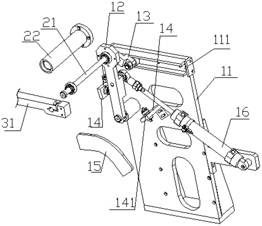
fig. 1 and fig. 2 are the structure diagrams of the present invention.
Fig. 3 is an application structure diagram of the present invention.
The specific implementation mode is as follows:
the present invention will be further described with reference to the accompanying drawings.
As shown in fig. 1 to fig. 3, the utility model relates to an electronic linkage structure of marking time of tourist sightseeing bus electric door, include mount 11, actuating arm 12, sliding arm 13, stopper 14, limiting plate 15, drive actuating cylinder 16, pivot 21, installation cover 22 and mounting bracket 31.
The top end of the driving arm 12 is hinged to the top end of the sliding arm 13, the bottom end of the driving arm 12 is rotatably connected to the fixed frame 11 through a bearing, and the bottom end of the sliding arm 13 is slidably connected to the fixed frame 11. The driving cylinder 16 is hinged on the fixed frame 11, and the cylinder shaft of the driving cylinder 16 is hinged with the driving arm 12.
Two limit blocks 14 are fixed on the fixed frame 11, two ends of a limit plate 15 are fixedly connected to the two limit blocks 14, and the limit plate 15 is arranged on the outer side of the driving arm 12. The driving arm 12 rotates in a space enclosed between the two limit blocks 14, the limit plate 15 and the fixing frame 11. The two limit blocks 14 are disposed at the upper limit and the lower limit of the rotation path of the driving arm 12, and each limit block 14 is provided with an approach switch 141. When the driving arm 12 moves to a range sensed by the proximity switch 141, the driving cylinder 16 stops moving.
The mounting sleeve 22 is fixedly connected to the driving arm 12, the rotating shaft 21 is rotatably connected to the inside of the mounting sleeve 22 through a bearing, one end of the rotating shaft 21 extends out of the mounting sleeve 22 and is fixedly connected with the mounting frame 31, and the rotating shaft 21 is perpendicular to the driving arm 12.
In order to realize the installation and fixation among the installation sleeve 22, the driving arm 12, the rotating shaft 21 and the installation frame 31, a flange surface is arranged at one end of the installation sleeve 22, and the flange surface of the installation sleeve 22 is fixedly connected with the driving arm 12.
Be equipped with right angle locking groove and the locking hole that communicates with right angle locking groove on mounting bracket 31, the end of pivot 21 stretches in the locking hole, wears to establish the bolt on right angle locking groove, with pivot 21 and mounting bracket 31 fixed connection.
In order to facilitate the sliding connection of the bottom end of the sliding arm 13 to the fixed frame 11, a sliding slot 111 is provided on the fixed frame 11, a pulley 131 is provided at the bottom end of the sliding arm 13, and the pulley 131 is slidably connected in the sliding slot 111.
During the installation, install electronic marking time on mounting bracket 31, the utility model provides a mounting bracket 31 is the rectangle frame structure, simplify mounting bracket 31 in fig. 1 and the figure 2.
When the passenger-friendly seat cushion is used, a triangular support is formed among the driving arm 12, the sliding arm 13 and the driving cylinder 16, the weight of passengers acts on the driving arm 12 and the sliding arm 13, the driving arm 12 and the sliding arm 13 share most of weight for the driving cylinder 16, the structure is stable, damage to the driving cylinder 16 is avoided, and the service life is prolonged.
The foregoing is only a preferred embodiment of the present invention, and it should be noted that, for those skilled in the art, several modifications can be made without departing from the principle of the present invention, and these modifications should also be regarded as the protection scope of the present invention.

Claims (6)

1.一种旅游观光车电动门电动踏步联动结构,其特征在于:包括固定架(11)、驱动臂(12)、滑动臂(13)、限位块(14)、限位板(15)、驱动气缸(16)、转轴(21)、安装套(22)和安装架(31),所述驱动臂(12)的顶端与滑动臂(13)的顶端相互铰接,驱动臂(12)的底端转动连接在固定架(11)上,滑动臂(13)的底端滑动连接在固定架(11)上,驱动气缸(16)铰接在固定架(11)上,且驱动气缸(16)的气缸轴与驱动臂(12)相铰接,在固定架(11)上固定两块限位块(14),限位板(15)的两端固定连接在两限位块(14)上,限位板(15)置于驱动臂(12)的外侧,两块限位块(14)置于驱动臂(12)的转动路径上,安装套(22)固定连接在驱动臂(12)上,转轴(21)通过轴承转动连接在安装套(22)内,且转轴(21)的一端伸出安装套(22)外并与安装架(31)固定连接。1. An electric stepping linkage structure for an electric door of a tourist vehicle, characterized in that it comprises a fixed frame (11), a driving arm (12), a sliding arm (13), a limit block (14), and a limit plate (15) , the driving cylinder (16), the rotating shaft (21), the mounting sleeve (22) and the mounting bracket (31), the top of the driving arm (12) and the top of the sliding arm (13) are hinged to each other, and the top of the driving arm (12) The bottom end is rotatably connected to the fixing frame (11), the bottom end of the sliding arm (13) is slidably connected to the fixing frame (11), the driving cylinder (16) is hinged on the fixing frame (11), and the driving cylinder (16) The cylinder shaft is hinged with the drive arm (12), two limit blocks (14) are fixed on the fixing frame (11), and both ends of the limit plate (15) are fixedly connected to the two limit blocks (14), The limit plate (15) is placed on the outer side of the drive arm (12), the two limit blocks (14) are placed on the rotation path of the drive arm (12), and the mounting sleeve (22) is fixedly connected to the drive arm (12) The rotating shaft (21) is rotatably connected in the mounting sleeve (22) through the bearing, and one end of the rotating shaft (21) extends out of the mounting sleeve (22) and is fixedly connected with the mounting frame (31). 2.如权利要求1所述的旅游观光车电动门电动踏步联动结构,其特征在于:所述固定架(11)上设有滑槽(111),在滑动臂(13)的底端设有滑轮(131),所述滑轮(131)滑动连接在滑槽(111)内。2. The electric step linkage structure of the electric door of a tourist sightseeing vehicle according to claim 1, characterized in that: the fixing frame (11) is provided with a chute (111), and the bottom end of the sliding arm (13) is provided with a chute (111) A pulley (131), the pulley (131) is slidably connected in the chute (111). 3.如权利要求1所述的旅游观光车电动门电动踏步联动结构,其特征在于:在每个限位块(14)上均设有接近开关(141)。3 . The electric stepping linkage structure of the electric door of a tourist sightseeing vehicle according to claim 1 , wherein a proximity switch ( 141 ) is provided on each limit block ( 14 ). 4 . 4.如权利要求1所述的旅游观光车电动门电动踏步联动结构,其特征在于:所述转轴(21)与驱动臂(12)相垂直。4 . The electric stepping linkage structure of the electric door of a tourist sightseeing vehicle according to claim 1 , wherein the rotating shaft ( 21 ) is perpendicular to the driving arm ( 12 ). 5 . 5.如权利要求1所述的旅游观光车电动门电动踏步联动结构,其特征在于:安装套(22)的一端设有法兰面,安装套(22)的法兰面与驱动臂(12)固定连接。5. The electric stepping linkage structure of the electric door of a tourist sightseeing vehicle according to claim 1, characterized in that: one end of the installation sleeve (22) is provided with a flange surface, and the flange surface of the installation sleeve (22) is connected to the drive arm (12). ) fixed connection. 6.如权利要求1所述的旅游观光车电动门电动踏步联动结构,其特征在于:在安装架(31)上设有直角锁紧槽以及与直角锁紧槽相连通的锁紧孔,转轴(21)的末端伸于锁紧孔内,在直角锁紧槽上穿设螺栓,将转轴(21)与安装架(31)固定连接。6. The electric step linkage structure of the electric door of a tourist sightseeing vehicle according to claim 1, characterized in that: a right-angle locking groove and a locking hole communicated with the right-angle locking groove are arranged on the mounting frame (31), and the rotating shaft The end of (21) protrudes into the locking hole, and bolts are inserted through the right-angle locking groove to fixedly connect the rotating shaft (21) and the mounting bracket (31).
CN202023219555.5U 2020-12-28 2020-12-28 Electric stepping linkage structure for electric door of tourist sightseeing vehicle Expired - Fee Related CN215204681U (en)

Priority Applications (1)

Application Number Priority Date Filing Date Title
CN202023219555.5U CN215204681U (en) 2020-12-28 2020-12-28 Electric stepping linkage structure for electric door of tourist sightseeing vehicle

Applications Claiming Priority (1)

Application Number Priority Date Filing Date Title
CN202023219555.5U CN215204681U (en) 2020-12-28 2020-12-28 Electric stepping linkage structure for electric door of tourist sightseeing vehicle

Publications (1)

Publication Number Publication Date
CN215204681U true CN215204681U (en) 2021-12-17

Family

ID=79435999

Family Applications (1)

Application Number Title Priority Date Filing Date
CN202023219555.5U Expired - Fee Related CN215204681U (en) 2020-12-28 2020-12-28 Electric stepping linkage structure for electric door of tourist sightseeing vehicle

Country Status (1)

Country Link
CN (1) CN215204681U (en)

Similar Documents

Publication Publication Date Title
CN103470089B (en) A kind of remote control parking stall lock of closed-loop control
CN209776317U (en) Electric pedal driving support
CN206141447U (en) Automatic flexible running -board in car outside
CN213359785U (en) Cab side window mechanism
CN103255969B (en) Vehicle door hinge mechanism and method for opening and closing vehicle door through same
CN107433840B (en) Automobile built-in panoramic sunroof
CN209114385U (en) Manual and electric two drives flat-open type barrier machine
CN208117666U (en) Fixing tool is used in a kind of detection of roll shaft
CN216767056U (en) Car and door connection mechanism
CN2934169Y (en) Adjustable automatic gate locking device
CN113708565B (en) Installation fixing device and method for various engine interfaces
CN210343070U (en) An electric lift rod and an automobile
CN211596555U (en) But road parking stall of height-adjusting by oneself parking with ware of parking
CN220745237U (en) Lifting equipment for automobile detection
CN113135245A (en) Door hinge assembly fixture
CN219931784U (en) Rotary lifter auxiliary device of round garage
CN218805529U (en) A car pedal device
CN114687627A (en) Automobile and door connecting mechanism
CN210026979U (en) Engineering machine tool door structure
CN223620097U (en) Rail supporting mechanism
CN215706732U (en) Vehicle is from lift spare tyre case
CN220670941U (en) Van tail door overturning opening and closing device
CN221477332U (en) Auto-parts installing support
CN224034920U (en) Durable testing arrangement of hinge
CN218059813U (en) Road leveling device that shakes

Legal Events

Date Code Title Description
GR01 Patent grant
GR01 Patent grant
CF01 Termination of patent right due to non-payment of annual fee

Granted publication date: 20211217

CF01 Termination of patent right due to non-payment of annual fee