SUMMERY OF THE UTILITY MODEL
The utility model discloses a main aim at provides a repeatedly usable's high strength environmental protection injection mold, can effectively solve the problem in the background art.
In order to achieve the above purpose, the utility model adopts the following technical scheme:
a reusable high-strength environment-friendly injection mold comprises a workbench, wherein four support rods are fixedly mounted on the lower surface of the workbench and are parallel to each other, a placement groove is formed in the middle of the upper surface inside the placement groove, a sliding plate is fixedly mounted at the left end of the upper surface of the workbench, a collecting box is arranged at the lower end of the sliding plate, a mold mechanism is mounted at the upper end of the workbench, a discharging mechanism is arranged at the right end of the workbench, an injection molding mechanism is arranged at the rear end of the workbench and comprises a lower template shell and a first fixing rod, the lower template shell is fixedly mounted inside the placement groove, a lower template chassis is movably mounted inside the lower template shell, the middle of the lower surface of the lower template chassis is fixedly connected with the upper end of a push rod, the injection molding mechanism comprises a first fixing plate and a feed pipe, and the first fixing plate is fixedly mounted at the rear end of the workbench, a sliding groove is formed in the middle of the upper surface of the first fixing plate, a lead screw is movably arranged in the sliding groove in a penetrating mode, the right end of the lead screw movably penetrates through the sliding groove and is fixedly connected with the output end of the motor, and the discharging mechanism comprises a third fixing plate.
Preferably, the lower end of the push rod movably penetrates through the lower end of the lower template shell and is fixedly connected with the output end of a second cylinder, the second cylinder is installed inside the groove, the upper surface of the lower template shell is provided with a plurality of fixing holes which are parallel to each other, the first fixing rod is provided with four fixing holes which are fixedly installed on the upper surface of a workbench and parallel to each other, and the upper end of the four fixing rods is fixedly provided with a supporting plate.
Preferably, the first air cylinder is fixedly installed in the middle of the upper surface of the supporting plate through a fixing frame, the output end of the first air cylinder is fixedly connected with the upper end of the pressing rod, the lower end of the pressing rod movably penetrates through the supporting plate and is fixedly connected with the middle of the upper surface of the upper template, a plurality of inserting rods are arranged on the periphery of the lower surface of the upper template and are parallel to each other, and the plurality of inserting rods are parallel to the fixing hole.
Preferably, a sliding block is movably mounted inside the sliding groove, the lower end of the sliding block movably penetrates through the mounting screw rod through threads, a second fixing plate is fixedly mounted on the upper surface of the sliding block, a second fixing rod is fixedly mounted in the middle of the right side of the upper surface of the second fixing plate, a heating barrel is fixedly mounted at the upper end of the second fixing rod, and a sealing cover is mounted at the upper end of the heating barrel through threads.
Preferably, the heating rod is installed in the middle of the lower surface in the sealing cover, the handle is fixedly installed in the middle of the upper surface of the sealing cover, the feed inlet is formed in the left end of the upper surface of the sealing cover, the discharge pipe is fixedly installed at the lower end of the heating barrel, the lower end of the discharge pipe is fixedly installed on the first fixing block in a penetrating mode, the lower end of the first fixing block is fixedly installed on the upper surface of the first fixing plate, the lower end of the feed pipe is fixedly installed on the upper surface of the upper template in a penetrating mode, and the feed pipe is parallel to the discharge pipe.
As preferred, No. three fixed plate fixed mounting are in the workstation right side, No. three fixed plate upper surface fixed mounting fixed block No. two, the installation movable rod is run through in the activity on No. two fixed blocks, movable rod left end and push pedal fixed connection, the movable rod right-hand member and No. three cylinder output fixed connection.
Compared with the prior art, the utility model discloses following beneficial effect has:
(1) the utility model discloses bolt and fixed orifices are mutually supported fixedly when moulding plastics, and the better template of guaranteeing when moulding plastics can not remove, and the better moulds plastics, and the environmental protection is sealed inside better cope match-plate pattern and lower bolster shell simultaneously to by No. two cylinders and lower bolster chassis and discharge mechanism's cooperation after the completion of moulding plastics, take off the raw materials then collect simple safety by the collecting box.
(2) When needs are moulded plastics, seal the lid and install in heating barrel upper end and carry out fixed heating to it, can take off sealed lid and wash heating barrel inside when need not heating it, better assurance this injection mold's life, better let its used repeatedly to it mould plastics.
Detailed Description
The technical solutions in the embodiments of the present invention will be described clearly and completely below with reference to the embodiments of the present invention, and it is obvious that the described embodiments are only some embodiments of the present invention, not all embodiments. Based on the embodiments in the present invention, all other embodiments obtained by a person skilled in the art without creative work belong to the protection scope of the present invention.
Examples
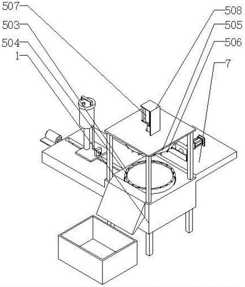
As shown in FIGS. 1-4, a reusable high-strength environment-friendly injection mold comprises a workbench 1, four support rods 2 fixedly mounted on the lower surface of the workbench 1 are parallel to each other, a placement groove 101 is arranged in the middle of the upper surface of the workbench 1, a groove 102 is arranged in the middle of the upper surface inside the placement groove 101, a sliding plate 3 is fixedly mounted on the left end of the upper surface of the workbench 1, a collection box 4 is arranged at the lower end of the sliding plate 3, a mold mechanism 5 is mounted at the upper end of the workbench 1, a discharge mechanism 7 is arranged at the right end of the workbench 1, an injection mechanism 6 is arranged at the rear end of the workbench 1, the mold mechanism 5 comprises a lower template shell 503 and a first fixing rod 501, the lower template shell 503 is fixedly mounted inside the placement groove 101, a lower template chassis 512 is movably mounted inside the lower template shell 503, the middle of the lower surface of the lower template chassis 512 is fixedly connected with the upper end of a push rod 511, the injection mechanism 6 comprises a first fixing plate 601 and a feed pipe 613, a fixed plate 601 is fixedly arranged at the rear end of the workbench 1, a sliding groove 602 is arranged in the middle of the upper surface of the fixed plate 601, a screw rod 603 is movably arranged in the sliding groove 602 in a penetrating mode, the right end of the screw rod 603 movably penetrates through the sliding groove 602 and is fixedly connected with the output end of a motor 604, and the discharging mechanism 7 comprises a third fixed plate 701.
Through the technical scheme, the mould mechanism 5 is fixed to be carried out the mould and is let to mould plastics more stably safety, and it is more convenient that the mechanism 6 of moulding plastics simultaneously heats the raw materials and moulds plastics, and the cooling is accomplished by ejection of plastics of 7 release cooling completions of discharge mechanism after the cooling of moulding plastics is accomplished simultaneously, is collected by collecting box 4, whole simple safety, and is more swift and convenient.
When the fixing device is specifically arranged, the lower end of the push rod 511 movably penetrates through the lower end of the lower template shell 503 and is fixedly connected with the output end of the second air cylinder 510, the second air cylinder 510 is installed inside the groove 102, the upper surface of the lower template shell 503 is provided with a plurality of fixing holes 504 which are parallel to each other, the first fixing rod 501 is provided with four fixing rods which are fixedly installed on the upper surface of the workbench 1 and are parallel to each other, and the supporting plate 502 is fixedly installed at the upper ends of the four first fixing rods 501. When injection molding is needed, the second cylinder 510 drives the push rod 511, the push rod 511 drives the lower template chassis 512 to move downwards, and the lower template chassis 512 is connected with the lower template shell 503.
When the device is specifically arranged, a first air cylinder 507 is fixedly arranged in the middle of the upper surface of the supporting plate 502 through a fixing frame 508, the output end of the first air cylinder 507 is fixedly connected with the upper end of a pressure lever 509, the lower end of the pressure lever 509 movably penetrates through the supporting plate 502 and is fixedly connected with the middle of the upper surface of an upper template 505, a plurality of inserting rods 506 are arranged on the periphery of the lower surface of the upper template 505 and are parallel to each other, and the inserting rods 506 are parallel to the fixing holes 504. The output end of the first air cylinder 507 drives the pressing rod 509 to move downwards, the pressing rod 509 drives the upper template 505 to move downwards, and the plurality of inserting rods 506 arranged on the lower surface of the upper template 505 are clamped into the fixing holes 504 to fix the upper template 505 and the lower template shell 503.
When the device is specifically arranged, a sliding block 605 is movably mounted in the sliding groove 602, the lower end of the sliding block 605 movably penetrates through the mounting screw rod 603 through threads, a second fixing plate 606 is fixedly mounted on the upper surface of the sliding block 605, a second fixing rod 607 is fixedly mounted in the middle of the right side of the upper surface of the second fixing plate 606, a heating barrel 608 is fixedly mounted at the upper end of the second fixing rod 607, and a sealing cover 609 is mounted at the upper end of the heating barrel 608 through threads. The motor 604 controls the slide block 605 to move back and forth through the screw 603, the slide block 605 drives the second fixing plate 606 to move, and the second fixing plate 606 drives the heating barrel 608 and the feeding pipe 613 to move and is clamped into the feeding pipe 613.
During specific setting, a heating rod 610 is arranged in the middle of the lower surface of the inner portion of the sealing cover 609, a handle 612 is fixedly arranged in the middle of the upper surface of the sealing cover 609, a feeding hole 611 is formed in the left end of the upper surface of the sealing cover 609, a discharging pipe 614 is fixedly arranged at the lower end of the heating barrel 608, the lower end of the discharging pipe 614 is fixedly arranged on a first fixing block 615 in a penetrating mode, the lower end of the first fixing block 615 is fixedly arranged on the upper surface of the first fixing plate 601, the lower end of a feeding pipe 613 is fixedly arranged on the upper surface of the upper die plate 505 in a penetrating mode, and the feeding pipe 613 and the discharging pipe 614 are parallel to each other. Raw materials enter the heating barrel 608 through the feeding hole 611, then the heating rod 610 heats the raw materials, the heated raw materials are fed into the feeding pipe 613 through the discharging pipe 614, and then the heated raw materials are fed into a grinding tool through the feeding pipe 613 to be subjected to injection molding, so that the environment is protected, and the safety is improved.
When specifically setting up, No. three fixed plate 701 fixed mounting is in workstation 1 right side, No. two fixed block 702 of fixed surface mounting on No. three fixed plate 701, and the activity runs through installation movable rod 704 on No. two fixed block 702, and movable rod 704 left end and push pedal 705 fixed connection, movable rod 704 right-hand member and No. three cylinder 703 output fixed connection. After injection molding is completed, the output end of the third air cylinder 703 pushes the movable rod 704, the movable rod 704 pushes the push plate 705, and the push plate 705 pushes out the raw materials after injection molding to collect the raw materials.
This repeatedly usable's high strength environmental protection injection mold's theory of operation:
when the device is used, firstly, the second cylinder drives the push rod 511, the push rod 511 drives the lower template chassis 512 to move downwards, the lower template chassis 512 is connected with the lower template shell 503, then the output end of the first cylinder 507 drives the press rod 509 to move downwards, the press rod 509 drives the upper template 505 to move downwards, a plurality of insertion rods 506 arranged on the lower surface of the upper template 505 are clamped into the fixing holes 504 to fix the upper template 505 and the lower template shell 503, after the die is fixed, the motor 604 controls the slide block 605 to move forwards and backwards through the screw rod 603, the slide block 605 drives the second fixing plate 606 to move, the second fixing plate 606 drives the heating barrel 608 and the feeding pipe 613 to move and be clamped into the feeding pipe 613, after the installation, the raw material enters the heating barrel 608 through the feeding hole 611, then the heating rod 610 heats the raw material, and the heated raw material is sent to the feeding pipe 613 through the discharging pipe 614, then the raw materials are fed into a grinding tool through a feeding pipe 613 to be subjected to injection molding, the output end of a first air cylinder 507 drives a pressure rod 509 to move upwards after the injection molding is finished, the pressure rod 509 drives an upper template 505 to move upwards, the upper template 505 drives an insertion rod 506 to leave a lower template shell 503, then a second air cylinder 510 drives a push rod 511 to push upwards, the push rod 511 drives a lower template chassis 512 to move upwards, the lower template chassis 512 drives the raw materials subjected to injection molding to move upwards, the output end of a third air cylinder 703 drives a movable rod 704 after the injection molding is moved to a specified position, the movable rod 704 drives a push plate 705, the push plate 705 pushes the raw materials subjected to injection molding to collect the raw materials, and the raw materials slide into a collecting box 4 through a sliding plate 3 to be collected.
It should be noted that the specific types of the first cylinder 507, the second cylinder 510, and the third cylinder 703 are: MAL40x 500.
It should be noted that the specific types of the motor 604 are: Y112M-44 KWB 3.
It is noted that the specific model of the heating rod 610 is BST 002.
The basic principles and the main features of the invention and the advantages of the invention have been shown and described above. It will be understood by those skilled in the art that the present invention is not limited to the above embodiments, and that the foregoing embodiments and descriptions are provided only to illustrate the principles of the present invention without departing from the spirit and scope of the present invention. The scope of the invention is defined by the appended claims and equivalents thereof.