CN215201098U - Edge grinding machine for printed circuit board - Google Patents
Edge grinding machine for printed circuit board Download PDFInfo
- Publication number
- CN215201098U CN215201098U CN202023192351.7U CN202023192351U CN215201098U CN 215201098 U CN215201098 U CN 215201098U CN 202023192351 U CN202023192351 U CN 202023192351U CN 215201098 U CN215201098 U CN 215201098U
- Authority
- CN
- China
- Prior art keywords
- circuit board
- printed circuit
- workbench
- motor
- edge grinding
- Prior art date
- Legal status (The legal status is an assumption and is not a legal conclusion. Google has not performed a legal analysis and makes no representation as to the accuracy of the status listed.)
- Active
Links
- 238000005498 polishing Methods 0.000 claims abstract description 37
- 238000007688 edging Methods 0.000 claims abstract description 9
- 239000002699 waste material Substances 0.000 claims description 11
- 239000000428 dust Substances 0.000 claims description 7
- 238000003780 insertion Methods 0.000 claims description 6
- 230000037431 insertion Effects 0.000 claims description 6
- 230000000149 penetrating effect Effects 0.000 claims description 2
- 230000000694 effects Effects 0.000 abstract description 3
- 238000000034 method Methods 0.000 abstract description 2
- 239000007787 solid Substances 0.000 abstract description 2
- 230000000740 bleeding effect Effects 0.000 description 2
- 239000012141 concentrate Substances 0.000 description 2
- 238000010586 diagram Methods 0.000 description 2
- 230000004075 alteration Effects 0.000 description 1
- 230000009286 beneficial effect Effects 0.000 description 1
- 238000005520 cutting process Methods 0.000 description 1
- 238000007599 discharging Methods 0.000 description 1
- 238000005516 engineering process Methods 0.000 description 1
- 238000004519 manufacturing process Methods 0.000 description 1
- 238000012986 modification Methods 0.000 description 1
- 230000004048 modification Effects 0.000 description 1
- 230000002093 peripheral effect Effects 0.000 description 1
- 238000006467 substitution reaction Methods 0.000 description 1
- 238000003466 welding Methods 0.000 description 1
Images

Landscapes
- Grinding Of Cylindrical And Plane Surfaces (AREA)
Abstract
The utility model discloses a printed circuit board edge grinding machine, which relates to the technical field of printed circuit board processing, and solves the problems that the prior edge grinding of a circuit board mostly adopts workers to manually remove burrs or rough edges of the circuit board, the working efficiency is low, the edge grinding machine is also adopted to grind the rough edges of the burrs at the periphery of the circuit board, but the workers need to hold the circuit board for grinding operation, and the safety is poor; the technical scheme for solving the problems is right one, and the obtained effect is as follows: the front and back edges of the workbench are provided with a front and back edge polishing mechanism of the printed circuit board, which consists of a first polishing sheet, a first motor, a second polishing sheet and a second motor, and finally, the front and back edges of the printed circuit board can be mechanically polished; and set up solid fixed splint and movable clamp plate mechanism on the workstation and make up into the centre gripping subassembly, can treat the printed circuit board of edging and carry out the centre gripping, need not the artifical handheld fixed of processing personnel to can avoid printed circuit board to take place the skew at the edging in-process, and then ensured printed circuit board's processingquality.
Description
Technical Field
The utility model relates to a printed circuit board processing technology field, in particular to printed circuit board edging machine.
Background
The periphery of the circuit board is easy to cause burrs, burrs and the like due to stamping and cutting of equipment during production, and the burrs on the periphery of the circuit board are required to be processed after being polished before the circuit board is processed and welded with electronic components.
The present is polished to the circuit board and is adopted the workman to cut its burr or deckle edge by hand more, and work efficiency is low, also has the edging machine of adoption to polish to the peripheral burr deckle edge of circuit board and handles, but needs the handheld circuit board operation of polishing of workman, and the security is not good.
SUMMERY OF THE UTILITY MODEL
The utility model discloses a main aim at provides a printed circuit board edging machine can effectively solve the problem in the background art.
In order to achieve the above purpose, the utility model adopts the following technical scheme:
the utility model provides a printed circuit board edging machine, includes the workstation, workstation top rear side is opened and is equipped with a preformed groove one, and installs the abrasive disc one in the preformed groove one, abrasive disc one rear side is connected with its pivoted motor of drive, and a motor fixed mounting in the workstation rear side, workstation top front side is opened and is equipped with preformed groove two, and installs the abrasive disc two in the preformed groove two, two front sides of abrasive disc are connected with its pivoted motor of drive two, and No. two motors remove through a actuating mechanism drive, the welding of workstation bottom has the waste collection hopper, and workstation top intermediate position sets up the through-hole that a plurality of intervals set up, the workstation top still installs the centre gripping subassembly that is used for centre gripping processing printed circuit board.
Preferably, the driving mechanism comprises an electric push rod, the electric push rod is installed on the front side of the workbench through a fixing frame, and the output end of the rear side of the electric push rod is welded with the front end of the second motor.
Preferably, the clamping assembly comprises a fixed clamping plate welded on the left side of the top of the workbench and a movable clamping plate mechanism fixedly installed on the right side of the top of the workbench.
Preferably, the movable clamp plate mechanism comprises a vertical plate, a bolt rod, a pressure spring and a movable plate, the vertical plate is welded on the right side of the top of the workbench, the bolt rod is inserted on the vertical plate, the movable plate is welded at the left end of the bolt rod, the movable plate is connected with the top of the workbench in a sliding mode, the pressure spring is sleeved on the periphery of the left side of the bolt rod, and the right end of the pressure spring abuts against the left surface of the vertical plate.
Preferably, the circular installing port that a plurality of intervals set up, every are opened to the garbage collection hopper front side all install dust filter screen and air exhauster in the circular installing port, and the air exhauster is located dust filter screen front side.
Preferably, the bottom of the waste collection hopper is provided with a waste discharge port, and the bottom end of the right side of the waste discharge port is inserted with an insertion door through an insertion slot.
Preferably, the front side of the workbench is also provided with a circular reserved penetrating port for a second motor to penetrate through.
Compared with the prior art, the utility model discloses following beneficial effect has:
1. the utility model discloses, limit setting is by polishing a piece one, a motor, polishing piece two and No. two motor constitution printed circuit board back and forth polishing mechanism around through the workstation, can carry out the machinery operation of polishing to printed circuit board back and forth, has improved the security and the efficiency of the deckle edge burr of polishing to printed circuit board greatly.
2. The utility model discloses, through set up the centre gripping subassembly that is formed by solid fixed splint and movable clamp plate mechanism combination on the workstation, the printed circuit board that can treat the edging carries out centre gripping processing, need not the artifical handheld fixed of processing personnel to can avoid printed circuit board to take place the skew at the edging in-process, and then ensured printed circuit board's processingquality.
3. The utility model discloses, through set up the garbage collection hopper in the workstation bottom to supporting set up dust filter screen and air exhauster in the circular mounting hole of garbage collection hopper front side, thereby the air exhauster can pass through the effect of bleeding, and with the sweeps that the workstation top was polished and is produced pass through-hole, reserve tank one and reserve tank two collect the garbage collection hopper in, conveniently concentrate the emission, and then avoided the sweeps to spill at will and lead to the processing area comparatively in a jumble.
Drawings
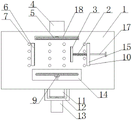
Fig. 1 is an overall structure diagram of the present invention.
Figure 2 is the utility model discloses a workstation and garbage collection hopper connection diagram.
In the figure: 1. a work table; 2. a pressure spring; 3. a movable plate; 4. a first motor; 5. grinding a first plate; 6. fixing the clamping plate; 7. a through hole; 8. a circular reserved through hole; 9. grinding a second plate; 10. a movable clamping plate mechanism; 11. a second motor; 12. a fixed mount; 13. an electric push rod; 14. a second reserved groove; 15. a vertical plate; 16. a waste collection hopper; 17. a latch rod; 18. reserving a first groove; 19. an exhaust fan; 20. a scrap discharge port; 21. inserting a door; 22. a circular mounting opening.
Detailed Description
The present invention will be described in further detail with reference to the drawings, wherein like elements are designated by like reference numerals, wherein the terms "front", "rear", "left", "right", "upper" and "lower", "bottom" and "top" used in the following description refer to the orientation in the drawings, and the terms "inner" and "outer" refer to the orientation toward or away from the geometric center of a particular element, respectively.
The technical solutions in the embodiments of the present invention will be described clearly and completely with reference to the accompanying drawings in the embodiments of the present invention, and it is obvious that the described embodiments are only some embodiments of the present invention, not all embodiments. Based on the embodiments in the present invention, all other embodiments obtained by a person skilled in the art without creative work belong to the protection scope of the present invention.
Referring to fig. 1-2, an edge grinding machine for printed circuit boards includes a worktable 1, a first pre-groove 18 is opened on the rear side of the top of the worktable 1, a polishing piece I5 is arranged in the reserved groove I18, the rear side of the polishing piece I5 is connected with a first motor 4 for driving the polishing piece I to rotate, and the first motor 4 is fixedly arranged at the rear side of the workbench 1, a second reserved groove 14 is arranged at the front side of the top of the workbench 1, a second polishing sheet 9 is arranged in the second reserved groove 14, the front side of the second polishing sheet 9 is connected with a second motor 11 for driving the second polishing sheet to rotate, and the second motor 11 is driven by a driving mechanism to move, a waste collecting hopper 16 is welded at the bottom of the workbench 1, and the middle position of the top of the workbench 1 is provided with a plurality of through holes 7 arranged at intervals, and the top of the workbench 1 is also provided with a clamping component for clamping and processing the printed circuit board.
Referring to fig. 1, in order to facilitate driving the second motor 11 and the second polishing sheet 9 to move back and forth at the front side of the worktable 1 according to the specification of the printed circuit board, and further to adjust the distance between the first polishing sheet 5 and the second polishing sheet 9, the driving mechanism includes an electric push rod 13, the electric push rod 13 is installed at the front side of the worktable 1 through a fixing frame 12, and the output end of the rear side of the electric push rod 13 is welded with the front end of the second motor 11.
Referring to fig. 1, in order to clamp and fix the edge-ground pcb, the clamping assembly includes a fixed clamping plate 6 welded to the left side of the top of the worktable 1 and a movable clamping plate mechanism 10 fixedly installed to the right side of the top of the worktable 1.
Referring to fig. 1, in order to cooperate with the fixing clamp plate 6 to clamp and fix the edge-ground printed circuit board, the moving clamp plate mechanism 10 includes a vertical plate 15, a latch rod 17, a pressure spring 2 and a movable plate 3, the vertical plate 15 is welded on the right side of the top of the workbench 1, the latch rod 17 is inserted in the vertical plate 15, the movable plate 3 is welded at the left end of the latch rod 17, the movable plate 3 is connected with the top surface of the workbench 1 in a sliding manner, the pressure spring 2 is sleeved on the left periphery of the latch rod 17, and the right end of the pressure spring 2 abuts against the left surface of the vertical plate 15.
Referring to fig. 2, in order to conveniently suck the waste generated by polishing the top of the worktable 1 by air suction, a plurality of circular mounting openings 22 are formed in the front side of the waste collecting hopper 16, a dust filter screen and an exhaust fan 19 are installed in each circular mounting opening 22, and the exhaust fan 19 is located in front of the dust filter screen.
Referring to fig. 2, in order to facilitate discharging the polishing scraps collected in the scrap collecting hopper 16, a scrap discharge port 20 is formed at the bottom of the scrap collecting hopper 16, and an insertion door 21 is inserted into the bottom end of the right side of the scrap discharge port 20 through an insertion slot.
Referring to fig. 2, in order to facilitate the driving mechanism to drive the second motor 11 to move back and forth in front of the workbench 1, a circular reserved through opening 8 for the second motor 11 to pass through is further formed in the front of the workbench 1.
The working principle is as follows: a processing person connects the power connection wire of the edge grinding machine with an external power supply mechanism in advance to ensure the power supply of an electric appliance on the workbench 1; when the printed circuit board is polished, a processing person can manually pull the bolt rod 17, the printed circuit board to be polished is placed between the clamping components, the rear side of the printed circuit board is tightly attached to the polishing disc I5, then the bolt rod 17 is slowly loosened, at the moment, the pressure spring 2 can push the movable plate 3 to move leftwards under the action of elastic force so as to match the fixed clamping plate 6 to clamp and fix the edge-polished printed circuit board, and the processing person does not need to manually hold and fix the printed circuit board; next, the processing personnel can start the electric push rod 13 to push the second motor 11 to drive the second motor 11 and the second polishing sheet 9 to move back and forth on the front side of the workbench 1, further adjust the distance between the first polishing sheet 5 and the second polishing sheet 9, and finally make the second polishing sheet 9 tightly attached to the front side of the printed circuit board; next, a processing person starts the first motor 4 and the second motor 11, so that the first motor and the second motor can respectively drive the first polishing sheet 5 and the second polishing sheet 9 to rotate, mechanical polishing operation of the front edge and the rear edge of the printed circuit board is further completed, and safety and efficiency of polishing burrs of the printed circuit board are greatly improved; after the front and rear sides of the printed circuit board are polished, a processing worker can rotate to adjust the printed circuit board to clamp and polish the printed circuit board again so as to finish the polishing operation of the other two sides; when the printed circuit board was polished, the processing personnel can start air exhauster 19 simultaneously to air exhauster 19 can pass through the effect of bleeding, and the sweeps that produces of polishing at the 1 top of workstation pass through-hole 7, reserve tank 18 and reserve tank two 14 and collect garbage collection hopper 16, conveniently concentrate the emission, and then avoided the sweeps to spill at will and lead to the processing area comparatively in a jumble.
Although embodiments of the present invention have been shown and described, it will be appreciated by those skilled in the art that changes, modifications, substitutions and alterations can be made in these embodiments without departing from the principles and spirit of the invention, the scope of which is defined in the appended claims and their equivalents.
Claims (7)
1. The utility model provides a printed circuit board edging machine, includes workstation (1), its characterized in that: a first reserved groove (18) is formed in the rear side of the top of the workbench (1), a first polishing sheet (5) is installed in the first reserved groove (18), the rear side of the polishing piece I (5) is connected with a first motor (4) for driving the polishing piece I to rotate, a first motor (4) is fixedly arranged at the rear side of the workbench (1), a second reserved groove (14) is arranged at the front side of the top of the workbench (1), a second polishing sheet (9) is arranged in the second reserved groove (14), the front side of the second polishing sheet (9) is connected with a second motor (11) for driving the second polishing sheet to rotate, a second motor (11) is driven to move by a driving mechanism, a waste collecting hopper (16) is welded at the bottom of the workbench (1), and a plurality of through holes (7) arranged at intervals are arranged in the middle position of the top of the workbench (1), and the top of the workbench (1) is also provided with a clamping assembly for clamping and processing the printed circuit board.
2. The edge grinding machine for printed circuit boards according to claim 1, characterized in that: the driving mechanism comprises an electric push rod (13), the electric push rod (13) is installed on the front side of the workbench (1) through a fixing frame (12), and the output end of the rear side of the electric push rod (13) is welded with the front end of the second motor (11).
3. The edge grinding machine for printed circuit boards according to claim 1, characterized in that: the clamping assembly comprises a fixed clamping plate (6) welded to the left side of the top of the workbench (1) and a movable clamping plate mechanism (10) fixedly installed on the right side of the top of the workbench (1).
4. A printed circuit board edge grinding machine according to claim 3, characterized in that: remove splint mechanism (10) and include riser (15), bolt pole (17), pressure spring (2) and fly leaf (3), riser (15) weld in workstation (1) top right side, and bolt pole (17) cartridge in on riser (15), fly leaf (3) weld in the left end of bolt pole (17), and fly leaf (3) slide with workstation (1) top surface and be connected, pressure spring (2) suit is in bolt pole (17) left side periphery, and pressure spring (2) right-hand member offsets with riser (15) left surface.
5. The edge grinding machine for printed circuit boards according to claim 1, characterized in that: waste material collection hopper (16) front side is opened circular installing port (22) that are equipped with a plurality of intervals and set up, every all install dust filter screen and air exhauster (19) in circular installing port (22), and air exhauster (19) are located dust filter screen front side.
6. A printed circuit board edge grinding machine according to claim 1 or 5, characterized in that: a scrap discharge port (20) is formed in the bottom of the waste collection hopper (16), and an insertion door (21) is inserted into the bottom end of the right side of the scrap discharge port (20) through an insertion slot.
7. The edge grinding machine for printed circuit boards according to claim 1, characterized in that: the front side of the workbench (1) is also provided with a circular reserved penetrating port (8) for a second motor (11) to penetrate through.
Priority Applications (1)
| Application Number | Priority Date | Filing Date | Title |
|---|---|---|---|
| CN202023192351.7U CN215201098U (en) | 2020-12-27 | 2020-12-27 | Edge grinding machine for printed circuit board |
Applications Claiming Priority (1)
| Application Number | Priority Date | Filing Date | Title |
|---|---|---|---|
| CN202023192351.7U CN215201098U (en) | 2020-12-27 | 2020-12-27 | Edge grinding machine for printed circuit board |
Publications (1)
| Publication Number | Publication Date |
|---|---|
| CN215201098U true CN215201098U (en) | 2021-12-17 |
Family
ID=79435632
Family Applications (1)
| Application Number | Title | Priority Date | Filing Date |
|---|---|---|---|
| CN202023192351.7U Active CN215201098U (en) | 2020-12-27 | 2020-12-27 | Edge grinding machine for printed circuit board |
Country Status (1)
| Country | Link |
|---|---|
| CN (1) | CN215201098U (en) |
Cited By (1)
| Publication number | Priority date | Publication date | Assignee | Title |
|---|---|---|---|---|
| CN115401563A (en) * | 2022-08-25 | 2022-11-29 | 维泰葛(山东)新材料有限公司 | Grinding and dust removing device for plate processing |
-
2020
- 2020-12-27 CN CN202023192351.7U patent/CN215201098U/en active Active
Cited By (2)
| Publication number | Priority date | Publication date | Assignee | Title |
|---|---|---|---|---|
| CN115401563A (en) * | 2022-08-25 | 2022-11-29 | 维泰葛(山东)新材料有限公司 | Grinding and dust removing device for plate processing |
| CN115401563B (en) * | 2022-08-25 | 2024-05-17 | 维泰葛(山东)新材料有限公司 | Grinding and dust removing device for plate processing |
Similar Documents
| Publication | Publication Date | Title |
|---|---|---|
| CN110919098B (en) | Numerical control cutting machine for steel structure machining | |
| CN219520619U (en) | Edge cutter for round edge workpiece | |
| CN210389520U (en) | Cutting device for office furniture processing | |
| CN217194573U (en) | Polishing device for end plate stamping part based on aluminum oil tank | |
| CN217776401U (en) | Lathe pushes down structure | |
| CN219521769U (en) | Environment-friendly milling waste material treatment structure | |
| CN110802482A (en) | Polishing machine with dust absorption function | |
| CN214561464U (en) | Vertical drilling machine convenient to clearance sweeps | |
| CN212497946U (en) | Panel cutting device with dust collector | |
| CN216151146U (en) | Environment-friendly energy-saving efficient drilling device | |
| CN211488991U (en) | An automatic CNC cutting machine for steel structure processing | |
| CN213034218U (en) | Grinding device for machining of rotor of cutting machine | |
| CN210938562U (en) | Dust removal device of platform grinding machine | |
| CN212443394U (en) | Milling cutter device for stainless steel processing with good chip removal performance | |
| CN217860524U (en) | Automatic change processing lathe | |
| CN210314774U (en) | Automatic wire cutting device of overlock machine for producing bandages | |
| CN217019469U (en) | Internal tooth type wheel hub processing tool | |
| CN218195725U (en) | Drilling equipment for wood working | |
| CN215469473U (en) | High-efficient touch panel processingequipment | |
| CN219213395U (en) | Elastic plate cutting machine | |
| CN215547145U (en) | A machining center waste collection device | |
| CN217991139U (en) | Sawing machine for plate processing | |
| CN210757045U (en) | Device for cutting floor | |
| CN221984561U (en) | Magnetic ring slotting equipment | |
| CN221044388U (en) | Sole deckle edge clearing device of new rubber material |
Legal Events
| Date | Code | Title | Description |
|---|---|---|---|
| GR01 | Patent grant | ||
| GR01 | Patent grant |