Automatic equipment of polishing of wood table support column
Technical Field
The utility model belongs to the technical field of furniture processing, specifically indicate an automatic equipment of polishing of wood table support column.
Background
In the furniture processing process, especially when the supporting columns of the wood table are ground, because the space between the supporting columns of the wood table is narrow, the grinding equipment is not easy to process the supporting columns, the supporting columns of the wood table need to be manually held by hands to independently process the supporting columns, and the method is difficult to operate, so that the production efficiency of the wood table is low, and dust is sucked manually due to manual processing to generate pneumoconiosis; and in the manual work use abrasive paper processing's in-process, polish to every support column alone and hardly guarantee that the volume of polishing is the same, lead to the support column to polish the quality variation. Therefore the utility model provides a can carry out sequence formula processing to the wood table support column automatically, the volume of polishing to every support column equals and the automatic equipment of polishing of efficient wood table support column.
SUMMERY OF THE UTILITY MODEL
In order to solve the problem, the utility model provides a can carry out sequence formula processing, to the automatic equipment of polishing of wooden table support column equal, efficient of polishing of every support column automatically to wooden table support column.
In order to realize the above functions, the utility model discloses the technical scheme who takes as follows: the automatic grinding equipment for the wood table supporting columns comprises a base, supporting columns and a grinding device, wherein the supporting columns are arranged on the base and play a role of fixing and supporting, so that the whole body is more stable; the polishing device comprises a driving motor, a driving gear, a transmission gear ring, a support rod, a rotary table, a through hole, a sliding chute, a sliding block, a polishing roller, a telescopic cylinder, a hinged support and a connecting rod, wherein the driving motor is arranged in a support column, the output end of the driving motor penetrates through the side wall of the support column, the driving gear is arranged at the output end of the driving motor, the transmission gear ring is arranged on the side wall of the support column, the transmission gear ring is meshed with the driving gear, the support rod is uniformly arranged on the side wall of the transmission gear ring in an annular array manner, the rotary table is arranged at one end of the support rod, which is far away from the transmission gear ring, the through hole penetrates through the central position of the rotary table, the sliding chute is embedded on the side wall of the rotary table, the sliding chutes are arranged in two groups by taking the vertical central line of the through hole as a symmetrical axis, the sliding block is clamped in the sliding chute, the polishing roller is arranged on the side wall of the sliding block, and the telescopic cylinder is arranged at the top end of the side wall of the rotary table, the telescopic cylinder is arranged on the vertical central line of the turntable, the hinged support is arranged below the output end of the telescopic cylinder, one end of the connecting rod is hinged with the hinged support, the other end of the connecting rod is hinged with the grinding roller, the connecting rods are arranged in two groups by taking the vertical central line of the hinged support as a symmetrical axis, the telescopic cylinder drives the hinged support to move through self telescopic, the hinged support drives the sliding block to slide in the sliding groove through the connecting rod, thereby the slide block drives the grinding rollers at the two sides to adjust the distance, after the grinding rollers at the two sides are adjusted to the distance suitable for grinding, the driving motor drives the driving gear to rotate, the driving gear drives the transmission gear ring to rotate, the transmission gear ring drives the turntable to rotate, thereby the carousel drives the roller of polishing and rotates, and the roller of polishing rotates the table leg that passes from the through-hole and polishes, can carry out sequence formula processing to the wooden table support column automatically, and is just efficient mutually to the volume of polishing of every support column.
Furthermore, a conveying table is arranged on the base.
Further, carry the even rotation of bench roof to be equipped with the conveying roller, be convenient for carry the table leg that needs to polish, carry the polishing to table leg automation.
Furthermore, evenly be equipped with the cushion under the base, play the effect of fixed stay, make whole more firm.
The utility model adopts the above structure to gain beneficial effect as follows: the utility model provides a pair of automatic equipment of polishing of wood table support column passes through grinding device's setting, telescopic cylinder drives articulated support through self is flexible and removes, articulated support passes through the connecting rod and drives the slider and slide in the spout, thereby the slider drives both sides polishing roller and carries out the distance regulation, adjust the distance back that is fit for polishing with both sides polishing roller, driving motor drives drive gear and rotates, drive gear drives the transmission ring gear and rotates, the transmission ring gear drives the carousel and rotates, thereby the carousel drives the polishing roller and rotates, the polishing roller rotates the table leg that passes from the through-hole and polishes, can carry out sequence formula processing to the wood table support column automatically, the volume of polishing to every support column is mutually just efficient, through the setting of carrying platform and conveying roller, be convenient for carry the table leg that needs to polish, polish to table leg automatic conveying.
Drawings
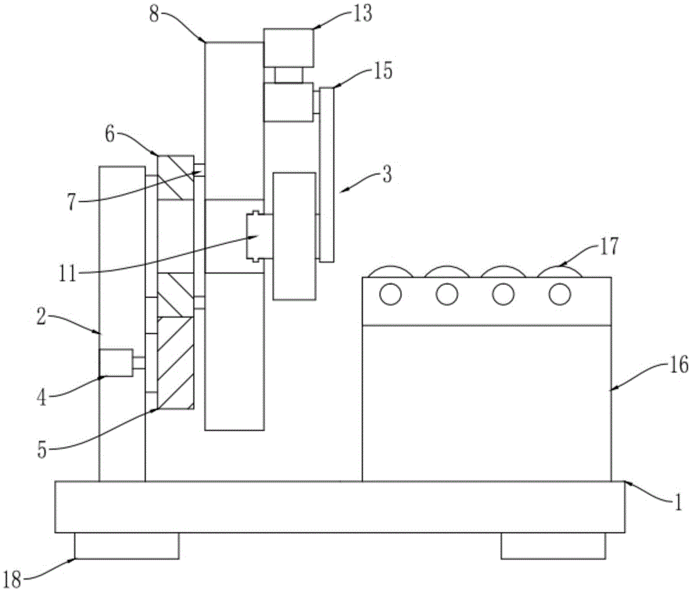
Fig. 1 is a schematic view of the overall structure of the automatic grinding equipment for the wood table support column of the present invention;
fig. 2 is a side view of the polishing device of the automatic polishing equipment for the wood table supporting column of the utility model.
The polishing device comprises a base 1, a base 2, a support column 3, a polishing device 4, a driving motor 5, a driving gear 6, a transmission gear ring 7, a support rod 8, a turntable 9, a through hole 10, a sliding groove 11, a sliding block 12, a polishing roller 13, a telescopic cylinder 14, a hinged support 15, a connecting rod 16, a conveying table 17, a conveying roller 18 and a cushion block.
Detailed Description
The technical solution of the present invention will be described clearly and completely with reference to the accompanying drawings, and obviously, the described embodiments are some, but not all embodiments of the present invention. Based on the embodiments in the present invention, all other embodiments obtained by a person skilled in the art without creative work belong to the protection scope of the present invention.
In the description of the present invention, it should be noted that the terms "center", "upper", "lower", "left", "right", "vertical", "horizontal", "inner", "outer", and the like indicate orientations or positional relationships based on the orientations or positional relationships shown in the drawings, and are only for convenience of description and simplification of description, but do not indicate or imply that the device or element referred to must have a specific orientation, be constructed and operated in a specific orientation, and thus, should not be construed as limiting the present invention. Furthermore, the terms "first," "second," and "third" are used for descriptive purposes only and are not to be construed as indicating or implying relative importance. The present invention will be described in further detail with reference to the accompanying drawings.
As shown in fig. 1-2, the automatic grinding device for the wood table support column of the present invention comprises a base 1, a support column 2 and a grinding device 3, wherein the support column 2 is arranged on the base 1, and the grinding device 3 is arranged on the support column 2; the polishing device 3 comprises a driving motor 4, a driving gear 5, a transmission gear ring 6, a support rod 7, a rotary table 8, a through hole 9, a sliding groove 10, a sliding block 11, a polishing roller 12, a telescopic cylinder 13, a hinged support 14 and a connecting rod 15, wherein the driving motor 4 is arranged in a support column 2, the output end of the driving motor 4 penetrates through the side wall of the support column 2, the driving gear 5 is arranged at the output end of the driving motor 4, the transmission gear ring 6 is arranged on the side wall of the support column 2, the transmission gear ring 6 is meshed with the driving gear 5, the support rod 7 is uniformly arranged on the side wall of the transmission gear ring 6 in an annular array manner, the rotary table 8 is arranged at one end of the support rod 7 far away from the transmission gear ring 6, the through hole 9 penetrates through the central position of the rotary table 8 to be arranged, the sliding groove 10 is embedded on the side wall of the rotary table 8, and the sliding groove 10 is arranged in two groups by taking the vertical central line of the through hole 9 as a symmetrical axis, the grinding device is characterized in that the sliding block 11 is slidably clamped in the sliding groove 10, the grinding roller 12 is arranged on the side wall of the sliding block 11, the telescopic cylinder 13 is arranged at the top end of the side wall of the rotating disc 8, the telescopic cylinder 13 is arranged on the vertical central line of the rotating disc 8, the hinged support 14 is arranged below the output end of the telescopic cylinder 13, one end of the connecting rod 15 is hinged to the hinged support 14, the other end of the connecting rod 15 is hinged to the grinding roller 12, and the connecting rods 15 are arranged in two groups by taking the vertical central line of the hinged support 14 as a symmetrical axis.
A conveying table 16 is arranged on the base 1.
Conveying rollers 17 are uniformly and rotatably arranged on the top wall of the conveying table 16.
And cushion blocks 18 are uniformly arranged below the base 1.
During the specific use, the table leg that will polish is put and is carried on conveying roller 17, carry the table leg in the middle of the both sides grinding roller 12, start telescopic cylinder 13, telescopic cylinder 13 drives articulated bearing 14 through self is flexible and removes, articulated bearing 14 drives slider 11 through connecting rod 15 and slides in spout 10, thereby slider 11 drives both sides grinding roller 12 and carries out the distance regulation, adjust both sides grinding roller 12 to the distance back that is fit for polishing, driving motor 4 drives drive gear 5 and rotates, drive gear 5 drives transmission ring gear 6 and rotates, transmission ring gear 6 drives carousel 8 and rotates, thereby carousel 8 drives grinding roller 12 and rotates, grinding roller 12 rotates the table leg that passes from through-hole 9 and polishes.
The present invention and the embodiments thereof have been described above, but the description is not limited thereto, and the embodiment shown in the drawings is only one of the embodiments of the present invention, and the actual structure is not limited thereto. In summary, those skilled in the art should understand that they should not be limited to the embodiments described above, and that they can design the similar structure and embodiments without departing from the spirit of the invention.