CN215160349U - Pile foundation handling device that hydraulic engineering used - Google Patents
Pile foundation handling device that hydraulic engineering used Download PDFInfo
- Publication number
- CN215160349U CN215160349U CN202121526543.9U CN202121526543U CN215160349U CN 215160349 U CN215160349 U CN 215160349U CN 202121526543 U CN202121526543 U CN 202121526543U CN 215160349 U CN215160349 U CN 215160349U
- Authority
- CN
- China
- Prior art keywords
- fixed
- pile foundation
- plate
- handling device
- cylinder
- Prior art date
- Legal status (The legal status is an assumption and is not a legal conclusion. Google has not performed a legal analysis and makes no representation as to the accuracy of the status listed.)
- Expired - Fee Related
Links
- 230000007246 mechanism Effects 0.000 claims abstract description 19
- 244000309464 bull Species 0.000 claims description 5
- 238000004519 manufacturing process Methods 0.000 abstract description 4
- 230000000694 effects Effects 0.000 abstract description 3
- XLYOFNOQVPJJNP-UHFFFAOYSA-N water Substances O XLYOFNOQVPJJNP-UHFFFAOYSA-N 0.000 description 7
- 238000001125 extrusion Methods 0.000 description 5
- 230000005540 biological transmission Effects 0.000 description 3
- 238000000034 method Methods 0.000 description 3
- 230000032258 transport Effects 0.000 description 3
- 241000282414 Homo sapiens Species 0.000 description 2
- 238000003825 pressing Methods 0.000 description 2
- 239000011435 rock Substances 0.000 description 2
- 230000004075 alteration Effects 0.000 description 1
- 230000009286 beneficial effect Effects 0.000 description 1
- 238000010276 construction Methods 0.000 description 1
- 230000004048 modification Effects 0.000 description 1
- 238000012986 modification Methods 0.000 description 1
- 239000000126 substance Substances 0.000 description 1
- 238000006467 substitution reaction Methods 0.000 description 1
- 239000002352 surface water Substances 0.000 description 1
- 230000007704 transition Effects 0.000 description 1
- 238000001363 water suppression through gradient tailored excitation Methods 0.000 description 1
Images


Landscapes
- Load-Engaging Elements For Cranes (AREA)
Abstract
The utility model discloses a pile foundation handling device that hydraulic engineering used relates to pile foundation transport technical field. The novel lifting device comprises a fixed seat, the bottom of fixing base is fixed with the jib, the pile foundation is installed to the bottom of jib, the bottom of fixing base is fixed with the supporting seat, the left side of supporting seat is fixed with the cylinder, the left side of cylinder is fixed with the grip block, the top of grip block is fixed with the stripper plate, the bottom of fixing base is provided with drive mechanism, drive mechanism includes the slide, the right side of slide is fixed with L type slide bar, the bottom of L type slide bar is provided with lifting mechanism, lifting mechanism includes the drum. This pile foundation handling device that hydraulic engineering used when fixing the pile foundation when on the jib, through starting the cylinder, makes the clamp plate remove left, and then has played the effect tight to the pile foundation clamp, prevents that the pile foundation production from rocking, and inconvenient staff removes when moving the pile foundation.
Description
Technical Field
The utility model relates to a pile foundation transport technical field specifically is a pile foundation handling device that hydraulic engineering used.
Background
Hydraulic engineering is an engineering built for controlling and allocating surface water and underground water in nature to achieve the purposes of removing harmful substances and benefiting. Also known as water engineering. Water is a valuable resource essential for human production and life, but its naturally occurring state does not completely meet the needs of human beings. Only when hydraulic engineering is built, water flow can be controlled, flood disasters are prevented, and water quantity is adjusted and distributed to meet the requirements of people on water resources in life and production. Hydraulic engineering needs to build various types of hydraulic buildings such as dams, dikes, spillways, water gates, water inlets, channels, transition troughs, rafts, fishways and the like so as to achieve the aims.
Hydraulic engineering is at the in-process of construction, needs prefabricated pile foundation sometimes, then drops into the stake hole with prefabricated pile foundation, at this in-process, needs remove the pile foundation, and current handling device is hoisted the pile foundation through the jib, transports again, probably causes the pile foundation to rock in the transportation, and inconvenient staff transports, if the jib does not have fixed tight pile foundation moreover, can cause the pile foundation to drop in the transportation, has great potential safety hazard.
SUMMERY OF THE UTILITY MODEL
Technical problem to be solved
Not enough to prior art, the utility model provides a pile foundation handling device that hydraulic engineering used has solved the problem that above-mentioned background art mentioned.
(II) technical scheme
In order to achieve the above purpose, the utility model discloses a following technical scheme realizes: the utility model provides a pile foundation handling device that hydraulic engineering used, includes the fixing base, the bottom of fixing base is fixed with the jib, the bottom of jib is fixed with the pile foundation, the bottom of fixing base is fixed with the supporting seat, the left side of supporting seat is fixed with the cylinder, the left side of cylinder is fixed with the grip block, the top of grip block is fixed with the stripper plate, the bottom of fixing base is provided with drive mechanism, drive mechanism includes the slide, the right side of slide is fixed with L type slide bar, the bottom of L type slide bar is provided with lifting mechanism, lifting mechanism includes the drum, the inner wall of drum is fixed with the bull stick, the right-hand member of bull stick is fixed with the gear, wheel and rack are intermeshing form, the bottom of rack is fixed with the backup pad.
Preferably, a spring is fixed on the right side of the sliding plate, the right side of the spring is fixed on the left side of the fixing block, and the top of the fixing block is fixed at the bottom of the fixing seat.
Preferably, a sliding groove for sliding the L-shaped sliding rod is formed on the surface of the cylinder.
Preferably, the supporting plate is provided with a slotted hole, the bottom of the slotted hole is provided with a cover plate, and the top of the cover plate is slidably mounted at the bottom of the supporting plate.
Preferably, the left end of the rotating rod is rotatably installed on the right side of the L-shaped connecting plate, and the right side of the L-shaped connecting plate is fixed on the left side of the supporting seat.
Preferably, the clamping plates are arranged in two groups, and the two groups of clamping plates are symmetrically arranged by taking the central line of the fixing seat in the vertical direction as a symmetry axis.
(III) advantageous effects
The utility model provides a pile foundation handling device that hydraulic engineering used. The method has the following beneficial effects:
(1) this pile foundation handling device that hydraulic engineering used when fixing the pile foundation when on the jib, through starting the cylinder, makes the clamp plate remove left, and then has played the effect tight to the pile foundation clamp, prevents that the pile foundation production from rocking, and inconvenient staff removes when moving the pile foundation.
(2) This pile foundation handling device that hydraulic engineering used, when the cylinder drove the grip block and removes left, can make the extrusion stem extrusion slider remove left, and then through the cooperation of L type slide bar, lifting mechanism, make the backup pad rise, make the apron support the pile foundation, prevent that the pile foundation from dropping in the transportation, safety more.
Drawings
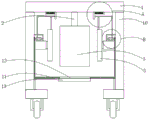
FIG. 1 is a schematic view of the front view structure of the whole device of the present invention;
FIG. 2 is an enlarged schematic view of the structure A of the present invention;
fig. 3 is an enlarged schematic view of the structure of the utility model B.
In the figure: 1. a fixed seat; 2. a boom; 3. a pile foundation; 4. a cylinder; 5. a clamping plate; 6. a pressing plate; 7. a transmission mechanism; 71. a slide plate; 72. an L-shaped sliding rod; 73. a spring; 74. a fixed block; 8. a lifting mechanism; 81. a cylinder; 82. a chute; 83. a rotating rod; 84. a gear; 85. a rack; 9. an L-shaped connecting plate; 10. a supporting seat; 11. a support plate; 12. a slot; 13. and (7) a cover plate.
Detailed Description
The technical solutions in the embodiments of the present invention will be described clearly and completely with reference to the accompanying drawings in the embodiments of the present invention, and it is obvious that the described embodiments are only some embodiments of the present invention, not all embodiments. Based on the embodiments in the present invention, all other embodiments obtained by a person skilled in the art without creative work belong to the protection scope of the present invention.
Referring to fig. 1-3, the present invention provides a technical solution: a pile foundation carrying device for hydraulic engineering comprises a fixed seat 1, a hanging rod 2 is fixed at the bottom of the fixed seat 1, a pile foundation 3 is fixed at the bottom of the hanging rod 2, a supporting seat 10 is fixed at the bottom of the fixed seat 1, an air cylinder 4 is fixed on the left side of the supporting seat 10, a clamping plate 5 is fixed on the left side of the air cylinder 4, the air cylinder 4 is further started to enable the clamping plate 5 to move leftwards, the pile foundation 3 is clamped, the pile foundation 3 is prevented from shaking during pile foundation 3 transportation, and inconvenient workers move, an extrusion plate 6 is fixed at the top of the clamping plate 5, a transmission mechanism 7 is arranged at the bottom of the fixed seat 1, the transmission mechanism 7 comprises a sliding plate 71, the top of the sliding plate 71 is slidably mounted at the bottom of the fixed seat 1, a spring 73 is fixed at the right side of the sliding plate 71, the right side of the spring 73 is fixed at the left side of a fixed block 74, the top of the fixed block 74 is fixed at the bottom of the fixed seat 1, an L-shaped sliding rod 72 is fixed at the right side of the sliding plate 71, when the clamping plate 5 moves leftwards, the pressing plate 6 presses the sliding plate 71 to move leftwards, the L-shaped sliding rod 72 is driven to move leftwards, the spring 73 is stretched, and the bottom of the L-shaped sliding rod 72 is provided with the lifting mechanism 8.
The lifting mechanism 8 comprises a cylinder 81, a sliding groove 82 for the sliding of the L-shaped sliding rod 72 is arranged on the surface of the cylinder 81, a rotating rod 83 is fixed on the inner wall of the cylinder 81, a gear 84 is fixed on the right end of the rotating rod 83, the back surface of the gear 84 is meshed with the front surface of a rack 85, the right side of the rack 85 is slidably arranged on the left side of the supporting seat 10, the left end of the rotating rod 83 is rotatably arranged on the right side of the L-shaped connecting plate 9, the right side of the L-shaped connecting plate 9 is fixed on the left side of the supporting seat 10, further, when the L-shaped sliding rod 72 slides leftwards in the sliding groove 82, the cylinder 81 is driven to rotate anticlockwise, the rotating rod 83 rotates anticlockwise, the gear 84 rotates anticlockwise, the rack 85 moves upwards, a supporting plate 11 is fixed at the bottom of the rack 85, a slotted hole 12 is arranged on the surface of the supporting plate 11, a cover plate 13 is arranged at the bottom of the slotted hole 12, the top of the cover plate 13 is slidably arranged at the bottom of the supporting plate 11, rack 85 upward movement drives backup pad 11 upward movement, make apron 13 support pile foundation 3, prevent to prevent that pile foundation 3 from dropping when transporting, when transporting pile foundation 3 to the assigned position, start cylinder 4 and make clamp plate 5 remove to the right, make stripper plate 6 not contact with extrusion slide 71, be in tensile state because of spring 73, make L type slide bar 72 remove to the right in spout 82, make drum 81 clockwise rotation, rack 85 descends, make apron 13 no longer support pile foundation 3, through opening apron 13, make pile foundation 3 place at the assigned position from slotted hole 12.
During operation (or during the use), when transporting pile foundation 3, start through cylinder 4, make clamp plate 5 remove left, it is fixed to press from both sides the clamp plate 3, prevent when transporting pile foundation 3, pile foundation 3 takes place to rock, inconvenient staff removes, when clamp plate 5 removes left, can make stripper plate 6 extrusion slide 71 remove left, slide 71 drives L type slide bar 72 and removes left, make drum 81 anticlockwise rotation, make backup pad 11 remove upwards, make apron 13 support pile foundation 3, prevent that pile foundation 3 from dropping in the transportation, cause certain potential safety hazard for the staff, and cause pile foundation 3 to damage easily.
Although embodiments of the present invention have been shown and described, it will be appreciated by those skilled in the art that changes, modifications, substitutions and alterations can be made in these embodiments without departing from the principles and spirit of the invention, the scope of which is defined in the appended claims and their equivalents.
Claims (6)
1. The utility model provides a pile foundation handling device that hydraulic engineering used, includes fixing base (1), its characterized in that: the bottom of fixing base (1) is fixed with jib (2), the bottom of jib (2) is fixed with pile foundation (3), the bottom of fixing base (1) is fixed with supporting seat (10), the left side of supporting seat (10) is fixed with cylinder (4), the left side of cylinder (4) is fixed with pinch plate (5), the top of pinch plate (5) is fixed with stripper plate (6), the bottom of fixing base (1) is provided with drive mechanism (7), drive mechanism (7) includes slide (71), the right side of slide (71) is fixed with L type slide bar (72), the bottom of L type slide bar (72) is provided with lifting mechanism (8), lifting mechanism (8) includes drum (81), the inner wall of drum (81) is fixed with bull stick (83), the right-hand member of bull stick (83) is fixed with gear (84), the gear (84) and the rack (85) are meshed with each other, and a support plate (11) is fixed at the bottom of the rack (85).
2. The pile foundation handling device of claim 1, wherein: a spring (73) is fixed on the right side of the sliding plate (71), the right side of the spring (73) is fixed on the left side of the fixed block (74), and the top of the fixed block (74) is fixed on the bottom of the fixed seat (1).
3. The pile foundation handling device of claim 1, wherein: the surface of the cylinder (81) is provided with a sliding chute (82) for the L-shaped sliding rod (72) to slide.
4. The pile foundation handling device of claim 1, wherein: slotted holes (12) are formed in the supporting plate (11), a cover plate (13) is arranged at the bottom of each slotted hole (12), and the top of each cover plate (13) is slidably mounted at the bottom of the supporting plate (11).
5. The pile foundation handling device of claim 1, wherein: the left end of bull stick (83) rotates and installs the right side at L type connecting plate (9), the left side at supporting seat (10) is fixed on the right side of L type connecting plate (9).
6. The pile foundation handling device of claim 1, wherein: the clamping plates (5) are arranged in two groups, and the two groups of clamping plates (5) are symmetrically arranged by taking the central line in the vertical direction of the fixing seat (1) as a symmetry axis.
Priority Applications (1)
| Application Number | Priority Date | Filing Date | Title |
|---|---|---|---|
| CN202121526543.9U CN215160349U (en) | 2021-07-06 | 2021-07-06 | Pile foundation handling device that hydraulic engineering used |
Applications Claiming Priority (1)
| Application Number | Priority Date | Filing Date | Title |
|---|---|---|---|
| CN202121526543.9U CN215160349U (en) | 2021-07-06 | 2021-07-06 | Pile foundation handling device that hydraulic engineering used |
Publications (1)
| Publication Number | Publication Date |
|---|---|
| CN215160349U true CN215160349U (en) | 2021-12-14 |
Family
ID=79401352
Family Applications (1)
| Application Number | Title | Priority Date | Filing Date |
|---|---|---|---|
| CN202121526543.9U Expired - Fee Related CN215160349U (en) | 2021-07-06 | 2021-07-06 | Pile foundation handling device that hydraulic engineering used |
Country Status (1)
| Country | Link |
|---|---|
| CN (1) | CN215160349U (en) |
-
2021
- 2021-07-06 CN CN202121526543.9U patent/CN215160349U/en not_active Expired - Fee Related
Similar Documents
| Publication | Publication Date | Title |
|---|---|---|
| CN214149966U (en) | Water quality sampling device for hydraulic engineering | |
| CN210975746U (en) | A curved stacked beam gate with layered water intake function | |
| CN106185690A (en) | A kind of building retaining wall automatic lifting Handling device | |
| CN214939893U (en) | Hydraulic engineering sluice structure | |
| CN112554136A (en) | Construction equipment is laid to river course slope protection brick for hydraulic engineering | |
| CN218562272U (en) | Make things convenient for hydraulic engineering of dismouting to use fence of decontaminating | |
| CN217759231U (en) | Water storage structure | |
| CN111519581A (en) | Construction method of vertical water stop structure of hydraulic engineering | |
| CN215715087U (en) | Sluice for hydraulic engineering with clearance function | |
| CN216428280U (en) | A throw stone material equipment for throwing construction of stone silt-squeezing dyke | |
| CN215249007U (en) | Hook structure of prefabricated road deck of assembled | |
| CN221441398U (en) | Flood prevention mechanism of hydraulic engineering | |
| CN115450230A (en) | A backfilling device for laying water conservancy pipelines | |
| CN212740632U (en) | Water conservancy pile foundation handling device | |
| CN211141285U (en) | Cement promotes conveying equipment for cement manufacture | |
| CN210193267U (en) | A construction material hoist | |
| CN114737874A (en) | Foundation pile drilling equipment for building | |
| CN218287815U (en) | Handling device is used in hydraulic engineering pile foundation construction convenient to use | |
| CN220866584U (en) | Single-port rotary blanking and distributing machine | |
| CN220057603U (en) | Construction equipment for replacing inverted arch of high-speed railway tunnel | |
| CN219950114U (en) | Water conservancy construction pay-off | |
| CN216583050U (en) | Waterproofing membrane finished product pile up neatly equipment | |
| CN215888162U (en) | A water conservancy construction water canal cleaning device | |
| CN214219588U (en) | Sectional type drainage gate | |
| CN217758613U (en) | Sluice for hydraulic engineering |
Legal Events
| Date | Code | Title | Description |
|---|---|---|---|
| GR01 | Patent grant | ||
| GR01 | Patent grant | ||
| CF01 | Termination of patent right due to non-payment of annual fee | ||
| CF01 | Termination of patent right due to non-payment of annual fee |
Granted publication date: 20211214 |