Angle-adjustable sawing machine
Technical Field
The utility model relates to a sawing machine technical field, in particular to but angle regulation's sawing machine.
Background
The sawing machine is characterized in that a circular saw blade performs rotary cutting motion and simultaneously performs feed motion along with a saw blade box, so that the material is cut; in the existing sawing machine structure, the sawing angle can not be cut as required, so that sawing machines with various different angles are required; this not only does not increase the equipment input cost, but also can occupy a large amount of spaces in the factory building.
SUMMERY OF THE UTILITY MODEL
An object of the utility model is to provide an adjustable angle's sawing machine to prior art's defect and not enough.
In order to achieve the above object, the utility model adopts the following technical scheme:
the utility model relates to an angle-adjustable sawing machine, which comprises a worktable, a cutting and sawing module fixing box rotationally connected on the worktable, and a swing angle adjusting mechanism for driving the cutting and sawing module fixing box to rotate on the worktable; the working table is provided with a lifting shield mechanism capable of moving up and down, a section conveying table for placing cutting materials and a pressing mechanism for pressing the cutting materials on the working table surface.
Furthermore, the swing angle adjusting mechanism comprises a connecting block fixed on the cutting and sawing module fixing box, a telescopic mechanism with one end hinged on the workbench and a swing rod fixed on the connecting block; the other end of the telescopic mechanism is hinged on the swing rod.
Further, an exhaust pipe is communicated with the cutting and sawing module fixing box.
Furthermore, the pressing mechanism comprises a pressing cylinder fixed on the workbench; and a compression block is fixed at the piston rod end of the material pressing cylinder.
Furthermore, the lifting shield mechanism comprises a lifting cylinder fixed on the workbench; the piston rod end of the lifting cylinder is fixed on the shield fixing frame; and a protective cover is fixed on the protective cover fixing frame.
Furthermore, a swing rod positioning groove matched with the swing rod is formed in the connecting block; one end of the swing rod positioning groove penetrates through the side wall of the connecting block; the swing rod is inserted into the swing rod positioning groove; a pin inserting hole which is vertical to the swing rod positioning groove is formed in the side wall of the connecting block; the pin inserting hole penetrates through the swing rod positioning groove; a pin hole is formed in the swing rod; a pin is inserted into the pin insertion hole; the pin penetrates through the pin insertion hole and then is inserted into the pin hole; an L-shaped plate is arranged on the connecting block; a concave shape is arranged on the inner side wall of the L-shaped plate; a spring piece is fixed on the pin body of the pin; the spring plate is provided with a convex shape embedded into the concave shape.
After the structure is adopted, the utility model discloses beneficial effect does: an adjustable angle's sawing machine, be provided with on the workstation can elevating movement the lift guard shield mechanism, be used for placing the section bar of cutting material and carry the platform and be used for compressing tightly the hold-down mechanism on table surface with the cutting material. When the utility model is used, the material to be cut is conveyed to the cutting position through the section bar conveying platform, the pressing mechanism presses the material on the workbench, and then the cutting mechanism cuts the material; the swing angle adjusting mechanism can adjust the angle of the saw disc on the cutting mechanism according to the angle required by the material, the use flexibility of the sawing machine is improved, the equipment investment cost is reduced, the space of a factory building is saved, the lifting shield mechanism can move up and down, and the lifting shield mechanism covers the position of cutting.
Drawings
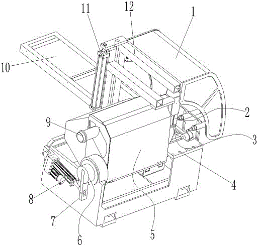
Fig. 1 is a schematic structural diagram of the present invention;
FIG. 2 is a view showing a connection structure of a connection block and a swing lever;
FIG. 3 is an enlarged view of section A of FIG. 2;
description of reference numerals:
1. a protective cover; 2. a material pressing cylinder; 3. a compression block; 4. a work table; 5. a cutting and sawing module fixing box;
6. connecting blocks; 601. a swing rod positioning groove; 602. inserting a pin into the hole; 7. a swing rod; 701. a pin hole;
8. a telescoping mechanism; 9. an air exhaust pipe; 10. a section bar conveying table; 11. a lifting cylinder;
12. a shield fixing frame; 13. a pin; 14. an L-shaped plate; 1401. a concave shape; 15. a spring plate;
1501. convex.
Detailed Description
The present invention will be further described with reference to the accompanying drawings.
As shown in fig. 1 to 3, the sawing machine with adjustable angle of the present invention comprises a worktable 4, a saw cutting module fixing box 5 rotatably connected to the worktable 4, and a swing angle adjusting mechanism for driving the saw cutting module fixing box 5 to rotate on the worktable 4; the workbench 4 is provided with a lifting shield mechanism capable of lifting, a section bar conveying platform 10 for placing cutting materials and a pressing mechanism for pressing the cutting materials on the surface of the workbench 4; a cutting mechanism is arranged in the cutting and sawing module fixing box 5, a material to be cut is conveyed to a cutting position through the section conveying table 10, the pressing mechanism presses the material on the workbench 4, and then the cutting mechanism cuts the material; the swing angle adjusting mechanism can adjust the angle of the saw disc on the cutting mechanism according to the angle required by the material, the use flexibility of the sawing machine is improved, the equipment investment cost is reduced, the space of a factory building is saved, the lifting shield mechanism can move up and down, and the lifting shield mechanism covers the position of cutting.
As a preferred mode of the utility model, the swing angle adjusting mechanism comprises a connecting block 6 fixed on the cutting and sawing module fixing box 5, a telescopic mechanism 8 with one end hinged on the worktable 4 and a swing rod 7 fixed on the connecting block 6; the other end of the telescopic mechanism 8 is hinged on the swing rod 7; the telescopic mechanism 8 is a servo electric cylinder and can accurately control the telescopic length; the swing rod 7 and the connecting block 6 are driven by the telescopic action of the servo electric cylinder to drive the saw module fixing box 5 to rotate on the workbench 4 to adjust the angle of the saw disc.
As a preferred mode of the utility model, the cutting and sawing module fixing box 5 is communicated with an air exhaust pipe 9; the air suction pipe 9 is communicated with an air inlet of the air purification device and is used for purifying the air inside the cutting and sawing module fixing box 5.
As a preferred mode of the utility model, the pressing mechanism comprises a pressing cylinder 2 fixed on a workbench 4; a piston rod end of the material pressing cylinder 2 is fixed with a pressing block 3; after the material reaches the cutting position, the material is pressed down through the material pressing cylinder 2, and the pressing block 3 presses the material tightly.
As a preferred mode of the present invention, the lifting guard mechanism includes a lifting cylinder 11 fixed on the working table 4; the piston rod end of the lifting cylinder 11 is fixed on the shield fixing frame 12; the protective cover 1 is fixed on the protective cover fixing frame 12; after the lifting cylinder 11 is driven, the protective cover 1 is driven to move up and down, so that the saw disc is convenient to replace.
As a preferred mode of the present invention, a swing link positioning groove 601 paired with the swing link 7 is provided on the connecting block 6; one end of the swing rod positioning groove 601 penetrates through the side wall of the connecting block 6; the swing rod 7 is inserted into the swing rod positioning groove 601; a pin insertion hole 602 which is perpendicular to the swing rod positioning groove 601 is formed in the side wall of the connecting block 6; the pin insertion hole 602 penetrates through the swing rod positioning groove 601; a pin hole 701 is formed in the swing rod 7; a pin 13 is inserted into the pin insertion hole 602; the pin 13 is inserted into the pin hole 701 after passing through the pin insertion hole 602; an L-shaped plate 14 is arranged on the connecting block 6; a concave 1401 is arranged on the inner side wall of the L-shaped plate 14; a spring piece 15 is fixed on the pin body of the pin 13; the spring piece 15 is provided with a convex shape 1501 embedded in the concave shape 1401; the convex shape 1501 is embedded into the concave shape 1401, so that the pin 13 cannot slide relative to the L-shaped plate 14, and the acting force of the spring piece 15 is added, so that the pin 13 cannot be pulled out of the pin hole 701, and the connection block 6 and the swing rod 7 are fixed; when the swing rod 7 needs to be pulled out of the pin hole 701, the spring piece 15 is only required to be pulled so that the convex shape 1501 is pulled out of the concave shape 1401, then the spring piece 15 is misaligned with the L-shaped plate 14, and the pin 13 can be pulled out of the pin hole 701.
When the utility model is used, the material to be cut is conveyed to the cutting position through the section bar conveying platform, after the material reaches the cutting position, the material is pressed down through the material pressing cylinder, the material is pressed tightly on the workbench through the pressing block, and then the material is cut by the cutting mechanism; the telescopic mechanism is a servo electric cylinder and can accurately control the telescopic length; the swing rod and the connecting block are driven by the telescopic action of the servo electric cylinder to drive the saw module fixing box to rotate on the workbench to adjust the angle of the saw disc, so that the using flexibility of the sawing machine is improved, the equipment investment cost is reduced, the space of a workshop is saved, and the lifting shield mechanism can move up and down and is covered at a cutting position; the pin cannot slide relative to the L-shaped plate by embedding the convex part into the concave part, and the pin cannot be pulled out of the pin hole by the action force of the spring piece, so that the connection block and the swing rod are fixed; when the swing rod is required to be pulled out of the pin hole, the spring piece is only required to be shifted to enable the convex part to be pulled out of the concave part, then the spring piece is staggered with the L-shaped plate, the pin can be pulled out of the pin hole, and the connecting block and the swing rod can be conveniently disassembled and assembled; the air suction pipe is communicated with an air inlet of the air purification device and used for purifying the air inside the cutting and sawing module fixing box.
The above is only the preferred embodiment of the present invention, so all the equivalent changes or modifications made by the structure, features and principles in accordance with the claims of the present invention are included in the claims of the present invention.