CN215129831U - Head position obstetric apparatus for obstetrical department - Google Patents
Head position obstetric apparatus for obstetrical department Download PDFInfo
- Publication number
- CN215129831U CN215129831U CN202022964684.0U CN202022964684U CN215129831U CN 215129831 U CN215129831 U CN 215129831U CN 202022964684 U CN202022964684 U CN 202022964684U CN 215129831 U CN215129831 U CN 215129831U
- Authority
- CN
- China
- Prior art keywords
- head position
- rotating shaft
- rod
- handle
- fixedly connected
- Prior art date
- Legal status (The legal status is an assumption and is not a legal conclusion. Google has not performed a legal analysis and makes no representation as to the accuracy of the status listed.)
- Expired - Fee Related
Links
- 238000013016 damping Methods 0.000 claims description 10
- 210000001215 vagina Anatomy 0.000 abstract description 4
- 238000000034 method Methods 0.000 description 5
- 238000005516 engineering process Methods 0.000 description 4
- 238000003745 diagnosis Methods 0.000 description 3
- 230000001850 reproductive effect Effects 0.000 description 3
- VYPSYNLAJGMNEJ-UHFFFAOYSA-N Silicium dioxide Chemical compound O=[Si]=O VYPSYNLAJGMNEJ-UHFFFAOYSA-N 0.000 description 2
- 238000003759 clinical diagnosis Methods 0.000 description 2
- 201000010099 disease Diseases 0.000 description 2
- 208000037265 diseases, disorders, signs and symptoms Diseases 0.000 description 2
- 239000003814 drug Substances 0.000 description 2
- 230000002265 prevention Effects 0.000 description 2
- 238000011160 research Methods 0.000 description 2
- 239000000741 silica gel Substances 0.000 description 2
- 229910002027 silica gel Inorganic materials 0.000 description 2
- 208000036818 High risk pregnancy Diseases 0.000 description 1
- 210000003484 anatomy Anatomy 0.000 description 1
- 230000009286 beneficial effect Effects 0.000 description 1
- 238000001514 detection method Methods 0.000 description 1
- 230000000694 effects Effects 0.000 description 1
- 230000002124 endocrine Effects 0.000 description 1
- 239000000463 material Substances 0.000 description 1
- 210000000056 organ Anatomy 0.000 description 1
- 231100000915 pathological change Toxicity 0.000 description 1
- 230000036285 pathological change Effects 0.000 description 1
- 230000001575 pathological effect Effects 0.000 description 1
- 230000007170 pathology Effects 0.000 description 1
- 230000035935 pregnancy Effects 0.000 description 1
- 238000001356 surgical procedure Methods 0.000 description 1
- 210000004243 sweat Anatomy 0.000 description 1
Images

Landscapes
- Accommodation For Nursing Or Treatment Tables (AREA)
Abstract
The utility model discloses a first position midwifery ware for obstetrical department, change hole, A pivot and expansion rod including sleeve, spout, slider, pull pole, A, the back fixedly connected with A sliding seat of expansion rod, B commentaries on classics hole has been seted up to the upper surface of A sliding seat, the inside swing joint in B commentaries on classics hole has the B pivot, the A sliding seat has the movable rod through B pivot swing joint, C commentaries on classics hole has been seted up to the upper surface of movable rod. The utility model has the main advantage of providing an obstetric apparatus is assisted with head position to obstetrical department, this equipment provides an practise midwifery structure, when using, medical personnel slowly promote the handle in to the sleeve, the slider then drives the A pivot and rotates, the A pivot makes expansion rod expand to the outside, hold baby's head position with the sucking disc gently at last, stimulate the handle backward again, medical personnel of being convenient for take over baby, expansion rod can expand pregnant woman's vagina simultaneously, the efficiency of practise midwifery has been improved.
Description
Technical Field
The utility model relates to an obstetrical department equipment technical field specifically is a first position midwifery ware for obstetrical department.
Background
The gynaecology and obstetrics is one of four main departments of clinical medicine, mainly researches the etiology, pathology, diagnosis and prevention of female reproductive organ diseases, physiological and pathological changes of pregnancy and delivery, high-risk pregnancy and difficult prevention and diagnosis, female reproductive endocrine, family planning, female health care and the like, deep researches on medical basic theories of modern molecular biology, oncology, genetics, reproductive endocrinology, immunology and the like and the progress of clinical diagnosis and treatment detection technology, widens and deepens the development of the gynaecology and obstetrics, plays an important role in ensuring the health of the female body and reproduction and preventing and treating various gynecological diseases, is closely related to the clinical science of surgery, internal medicine, pediatrics and the like, needs modern diagnosis and treatment technology, clinical pharmacology, pathological embryology, anatomy, epidemiology and the like, and is a basic knowledge with characteristics and comprehensive clinical diagnosis and treatment technology, The obstetric apparatus is the medical equipment that the gynaecology and obstetrics of hospital is indispensable, and current obstetric apparatus for head position simple structure for the obstetric apparatus, and the practise midwifery efficiency is lower, the medical personnel's of being not convenient for operation simultaneously, and the suitability is relatively poor, has influenced pregnant woman and baby's comfort level, and then has reduced practise midwifery efficiency.
SUMMERY OF THE UTILITY MODEL
Technical problem to be solved
The utility model provides a head position midwifery device for obstetrical department, which solves the problem of the prior art.
(II) technical scheme
In order to achieve the above purpose, the utility model discloses a following technical scheme realizes: a head position obstetric apparatus for obstetrical department, which comprises a sleeve, wherein one side of the sleeve is provided with a chute, the inside of the chute is movably connected with a slide block, one end of the sliding block is fixedly connected with a drawing rod, the upper surface of the sliding block is provided with an A rotating hole, the inside of the rotating hole A is movably connected with a rotating shaft A, the slide block is movably connected with an expansion rod through the rotating shaft A, the back of the expansion rod is fixedly connected with an A movable seat, the upper surface of the A movable seat is provided with a B rotating hole, the inside of the B rotating hole is movably connected with a B rotating shaft, the A movable seat is movably connected with a movable rod through the B rotating shaft, the upper surface of the movable rod is provided with a C rotating hole, the interior of the C rotating hole is movably connected with a C rotating shaft, the movable rod is movably connected with a B movable seat through a C rotating shaft, one end of the pull rod is fixedly connected with a piston, and the other end of the pull rod is fixedly connected with a handle.
Optionally, a connecting rod is inserted into one end of the sleeve, and a sucker is fixedly connected to one end of the connecting rod.
Optionally, a gasket is fixedly connected to one side of the suction cup.
Optionally, the bottom of the sleeve is fixedly connected with a handle, and anti-skid grains are carved on the surfaces of the handle and the handle.
Optionally, the upper surface of the sleeve is fixedly connected with an assembly seat, a D-rotating hole is formed in the surface of the assembly seat, and a damping rotating shaft is movably connected inside the D-rotating hole.
Optionally, the assembly base is movably connected with a disc through a damping rotating shaft, and an illuminating lamp is arranged on the upper surface of the disc.
Optionally, a storage battery is arranged inside the disc, and the illuminating lamp is electrically connected with the storage battery through a wire.
(III) advantageous effects
The utility model provides a first position midwifery ware for obstetrical department possesses following beneficial effect:
the utility model has the advantages of the utility model provides an obstetric apparatus is assisted with head position to obstetrical department, this equipment provides an practise midwifery structure, when using, medical personnel can hold the handle by a hand, one holds the handle, slowly promote the handle to the sleeve is interior, the handle drives the slow forward movement of pull pole, the pull pole and then drives the piston and move forward, the slider then drives the A pivot and rotates, the A pivot makes the expansion pole expand to the outside, hold baby's head position gently with the sucking disc at last, stimulate the handle backward again, the medical personnel of being convenient for take over baby, the expansion pole can expand pregnant woman's vagina simultaneously, the efficiency of practise midwifery is improved.
The utility model has the advantages of the main advantages of providing an obstetric apparatus is assisted with head position to obstetrical department, this equipment provides an practise midwifery structure, at the in-process of delivering a child to the baby, can push away the disc to erect the state through the damping pivot, the battery can supply power to the light, the light can throw light on baby head position department, the medical personnel of being convenient for observe baby's position, and then the medical personnel of being convenient for take over to the baby, the suitability of equipment has been improved, medical personnel's operating pressure has been alleviateed.
Drawings
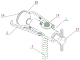
FIG. 1 is a schematic structural view of the present invention;
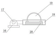
FIG. 2 is a schematic top view of the structure of the present invention;
fig. 3 is a schematic sectional view of the disc structure of the present invention.
In the figure: 1. a sleeve; 2. a slider; 3. a pull rod; 4. a, a rotating shaft; 5. an expansion rod; 6. a, a movable seat; 7. b, a rotating shaft; 8. a movable rod; 9. c, a rotating shaft; 10. b, a movable seat; 11. a piston; 12. a handle; 13. a suction cup; 14. a gasket; 15. a handle; 16. assembling a seat; 17. a damping rotating shaft; 18. a disc; 19. an illuminating lamp; 20. and (4) a storage battery.
Detailed Description
The technical solutions in the embodiments of the present invention will be described clearly and completely with reference to the accompanying drawings in the embodiments of the present invention, and it is obvious that the described embodiments are only some embodiments of the present invention, not all embodiments.
Referring to fig. 1 to 3, the present invention provides a technical solution: a head position obstetric apparatus for obstetrical department comprises a sleeve 1, one side of the sleeve 1 is provided with a chute, the inside of the chute is movably connected with a slide block 2, one end of the slide block 2 is fixedly connected with a pull rod 3, the upper surface of the slide block 2 is provided with an A rotating hole, the inside of the A rotating hole is movably connected with an A rotating shaft 4, the slide block 2 is movably connected with an expansion rod 5 through the A rotating shaft, the back surface of the expansion rod 5 is fixedly connected with an A movable seat 6, the upper surface of the A movable seat 6 is provided with a B rotating hole, the inside of the B rotating hole is movably connected with a B rotating shaft 7, the A movable seat 6 is movably connected with a movable rod 8 through the B rotating shaft 7, the upper surface of the movable rod 8 is provided with a C rotating hole, the inside of the C rotating hole is movably connected with a C rotating shaft 9, the movable rod 8 is movably connected with a B movable seat 10 through the C rotating shaft 9, one end of the pull rod 3 is fixedly connected with a piston 11, the other end of the pull rod 3 is fixedly connected with a handle 12, one end of the sleeve 1 is inserted with a connecting rod, one end of the connecting rod is fixedly connected with a sucker 13, one side of the sucker 13 is fixedly connected with a gasket 14, the gasket 14 is made of silica gel, the gasket 14 can be in direct contact with the head of a baby in the midwifery process, the silica gel gasket 14 can avoid damage to the head of the baby in the midwifery process, the comfort level of the baby is improved, the protection performance of equipment is improved, the bottom of the sleeve 1 is fixedly connected with a handle 15, anti-slip lines are engraved on the surfaces of the handle 15 and a handle 12, when a medical worker holds the handle 15 and the handle 12, the anti-slip lines can increase the friction force between the handle 15, the handle 12 and the hand, the phenomenon that the hand of the medical worker sweats out to cause hand slip is avoided, and the midwifery efficiency is further influenced, the upper surface of the sleeve 1 is fixedly connected with an assembly seat 16, the surface of the assembly seat 16 is provided with a D rotating hole, and the inner part of the D rotating hole is movably connected with a damping rotating shaft 17, the assembly seat 16 is movably connected with a disc 18 through a damping rotating shaft 17, the upper surface of the disc 18 is provided with a lighting lamp 19, the inside of the disc 18 is provided with a storage battery 20, the lighting lamp 19 is electrically connected with the storage battery 20 through a lead, a medical worker can hold the handle 15 with one hand and hold the handle 12 with one hand, slowly push the handle 12 into the sleeve 1, the handle 12 drives the pull rod 3 to slowly move forwards, the pull rod 3 further drives the piston 13 to move forwards, the slide block 2 drives the rotating shaft A4 to rotate, the rotating shaft A4 enables the expansion rod 5 to expand outwards, finally, the suction cup 13 slightly sucks the head of the baby, and then pulls the handle 12 backwards, so that the medical worker can take up the baby, meanwhile, the expansion rod 5 can expand the vagina of a pregnant woman, the midwife efficiency is improved, in the midwife process of the baby, the disc 18 can be pushed to a vertical state through the damping rotating shaft 17, storage battery 20 can supply power to light 19, light 19 can throw light on baby's head position department, the medical personnel of being convenient for observe baby's position, and then the medical personnel of being convenient for deliver to the baby, the adaptability of equipment has been improved, medical personnel's operating pressure has been alleviateed, this obstetrical department is with head position obstetric apparatus does not involve complicated technology and accurate component, moreover, the raw and other materials source of this equipment is extensive, and is with low costs, can effectually satisfy the demand in market, therefore, obstetrical department has good market prospect and space with head position obstetric apparatus.
The electrical components presented in the document are all electrically connected with an external master controller and 220V mains, and the master controller can be a conventional known device controlled by a computer or the like.
In conclusion, when the obstetric apparatus for head position in obstetrical department is used, a medical staff can hold the handle 15 with one hand and hold the handle 12 with one hand, the handle 12 is slowly pushed into the sleeve 1, the handle 12 drives the pull rod 3 to slowly move forward, the pull rod 3 further drives the piston 13 to move forward, the slide block 2 drives the rotating shaft A4 to rotate, the rotating shaft A4 enables the expansion rod 5 to expand outwards, finally the sucking disc 13 lightly sucks the head position of the baby, the handle 12 is pulled backwards, so that the medical staff can conveniently take up the baby, meanwhile, the expansion rod 5 can expand the vagina of the pregnant woman, the efficiency of the obstetric is improved, in the process of the baby delivery, the disc 18 can be pushed to the vertical state through the damping rotating shaft 17, the storage battery 20 can supply power to the illuminating lamp 19, the head position of the baby can be illuminated, so that the medical staff can conveniently observe the position of the baby, thereby being convenient for medical personnel to deliver the baby, improving the adaptability of the device and reducing the working pressure of the medical personnel.
The above, only be the concrete implementation of the preferred embodiment of the present invention, but the protection scope of the present invention is not limited thereto, and any person skilled in the art is in the technical scope of the present invention, according to the technical solution of the present invention and the utility model, the concept of which is equivalent to replace or change, should be covered within the protection scope of the present invention.
Claims (7)
1. The utility model provides a head position midwifery ware for obstetrical department, includes sleeve (1), its characterized in that: a sliding groove is formed in one side of the sleeve (1), a sliding block (2) is movably connected inside the sliding groove, a drawing rod (3) is fixedly connected to one end of the sliding block (2), an A rotating hole is formed in the upper surface of the sliding block (2), an A rotating shaft (4) is movably connected inside the A rotating hole, an expansion rod (5) is movably connected to the sliding block (2) through the A rotating shaft, an A movable seat (6) is fixedly connected to the back of the expansion rod (5), a B rotating hole is formed in the upper surface of the A movable seat (6), a B rotating shaft (7) is movably connected inside the B rotating hole, a movable rod (8) is movably connected to the A movable seat (6) through the B rotating shaft (7), a C rotating hole is formed in the upper surface of the movable rod (8), a C rotating shaft (9) is movably connected inside the C rotating hole, and a B movable seat (10) is movably connected to the movable rod (8) through the C rotating shaft (9), one end of the drawing rod (3) is fixedly connected with a piston (11), and the other end of the drawing rod (3) is fixedly connected with a handle (12).
2. The obstetric head position midwife according to claim 1, wherein: the one end of sleeve (1) is pegged graft and is had the connecting rod, the one end fixedly connected with sucking disc (13) of connecting rod.
3. The obstetric head position midwife according to claim 2, wherein: one side of the sucker (13) is fixedly connected with a gasket (14).
4. The obstetric head position midwife according to claim 1, wherein: the bottom fixedly connected with handle (15) of sleeve (1), the surface of handle (15) and handle (12) is carved with anti-skidding line.
5. The obstetric head position midwife according to claim 1, wherein: the upper surface fixed connection of sleeve (1) has assembly seat (16), D commentaries on classics hole has been seted up on the surface of assembly seat (16), the inside swing joint in D commentaries on classics hole has damping pivot (17).
6. The obstetric head position midwife according to claim 5, wherein: the assembling seat (16) is movably connected with a disc (18) through a damping rotating shaft (17), and an illuminating lamp (19) is arranged on the upper surface of the disc (18).
7. The obstetric head position midwife device for obstetric department of claim 6, wherein: the inside of disc (18) is provided with battery (20), light (19) pass through between wire and the battery (20) electric connection.
Priority Applications (1)
| Application Number | Priority Date | Filing Date | Title |
|---|---|---|---|
| CN202022964684.0U CN215129831U (en) | 2020-12-11 | 2020-12-11 | Head position obstetric apparatus for obstetrical department |
Applications Claiming Priority (1)
| Application Number | Priority Date | Filing Date | Title |
|---|---|---|---|
| CN202022964684.0U CN215129831U (en) | 2020-12-11 | 2020-12-11 | Head position obstetric apparatus for obstetrical department |
Publications (1)
| Publication Number | Publication Date |
|---|---|
| CN215129831U true CN215129831U (en) | 2021-12-14 |
Family
ID=79378456
Family Applications (1)
| Application Number | Title | Priority Date | Filing Date |
|---|---|---|---|
| CN202022964684.0U Expired - Fee Related CN215129831U (en) | 2020-12-11 | 2020-12-11 | Head position obstetric apparatus for obstetrical department |
Country Status (1)
| Country | Link |
|---|---|
| CN (1) | CN215129831U (en) |
-
2020
- 2020-12-11 CN CN202022964684.0U patent/CN215129831U/en not_active Expired - Fee Related
Similar Documents
| Publication | Publication Date | Title |
|---|---|---|
| CN205307302U (en) | Gynecological delivery bed | |
| CN111419612A (en) | A operation treatment multifunctional bed for gynaecology and obstetrics's diagnosis | |
| CN211156153U (en) | Novel clinical production of gynaecology and obstetrics is assisted device | |
| CN213098068U (en) | Obstetric apparatus for obstetrical department | |
| CN209847339U (en) | A visual instrument for uterine cavity surgery in obstetrics and gynecology | |
| CN212547932U (en) | A new medicine feeding device for obstetric clinical use | |
| CN216754877U (en) | Gynaecology and obstetrics's medical treatment is with auxiliary device that helps labour | |
| CN206950181U (en) | Optimization-type Hysterosalpingocontrast sonography bed | |
| CN213665648U (en) | An obstetric suction cup midwifery device | |
| CN214318112U (en) | Obstetrical department fetal head attracts practise midwifery device | |
| CN215503314U (en) | Obstetric forceps for obstetrics and gynecology department | |
| CN213465857U (en) | Limbs supporting device for obstetrics and gynecology department | |
| CN213963592U (en) | Fetal head suction midwifery device for midwifery of obstetrics and gynecology department | |
| CN216676304U (en) | Medical diagnosis and treatment device for gynecological diseases | |
| CN214632833U (en) | Clinical urgent product obstetric table of gynaecology and obstetrics | |
| CN220175210U (en) | Obstetric apparatus is attracted to gynaecology and obstetrics's child head | |
| CN221750722U (en) | Head position midwifery device | |
| CN209899538U (en) | Obstetrics and gynecology fetal head suction midwifery device | |
| CN218635967U (en) | Gynaecology and obstetrics is with expanding palace device | |
| CN213465836U (en) | Gynecological examination table | |
| CN215914676U (en) | B-ultrasonic examination mobile equipment for obstetrics and gynecology department | |
| CN213237016U (en) | Novel special wrist lamp for gynecologist | |
| CN216222196U (en) | Obstetric table for obstetrics and gynecology department | |
| CN215820989U (en) | Special gynecological disease therapeutic instrument for gynecologist | |
| CN216021190U (en) | Perineum stitching auxiliary device for obstetrics and gynecology department |
Legal Events
| Date | Code | Title | Description |
|---|---|---|---|
| GR01 | Patent grant | ||
| GR01 | Patent grant | ||
| CP02 | Change in the address of a patent holder |
Address after: 277600 No. 202, unit 1, building 3, No. 95, Shangshang North Street, Weishan County, Jining City, Shandong Province Patentee after: Duan Chunyun Address before: 277600 No. 202, unit 1, building 3, No. 95, Shangshang North Street, Huishan County, Jining City, Shandong Province Patentee before: Duan Chunyun |
|
| CP02 | Change in the address of a patent holder | ||
| CF01 | Termination of patent right due to non-payment of annual fee |
Granted publication date: 20211214 |
|
| CF01 | Termination of patent right due to non-payment of annual fee |