CN215122292U - Feed crushing device convenient to clean - Google Patents
Feed crushing device convenient to clean Download PDFInfo
- Publication number
- CN215122292U CN215122292U CN202121366246.2U CN202121366246U CN215122292U CN 215122292 U CN215122292 U CN 215122292U CN 202121366246 U CN202121366246 U CN 202121366246U CN 215122292 U CN215122292 U CN 215122292U
- Authority
- CN
- China
- Prior art keywords
- gear
- crushing
- side wall
- rotating shaft
- crushing box
- Prior art date
- Legal status (The legal status is an assumption and is not a legal conclusion. Google has not performed a legal analysis and makes no representation as to the accuracy of the status listed.)
- Active
Links
Images

Abstract
The utility model relates to a feed crushing device convenient for cleaning, which comprises a crushing box and a box cover, wherein the outer side wall of the crushing box is fixedly provided with a first motor, the output end of the first motor is fixedly provided with a first gear, the first gear is meshed with a second gear, the side wall of the first gear, which is far away from the first motor, is fixedly provided with a first rotating shaft, one end of the first rotating shaft, which is far away from the first gear, is rotatably connected with the inner side wall of the crushing box, a first crushing blade is fixedly arranged on the first rotating shaft, one side wall of the second gear is rotatably connected with the inner side wall of the crushing box through a connecting shaft, the other side wall of the second gear is fixedly provided with a second rotating shaft, one end of the second rotating shaft, which is far away from the second gear, is rotatably connected with the inner side wall of the crushing box, a second crushing blade is fixedly arranged on the second rotating shaft, after the first motor is started, the first gear and the second gear can be driven to rotate, the first rotating shaft and the second rotating shaft are driven to rotate by the rotation of the first gear and the second gear, thereby make first crushing blade and second crushing blade rotate, realize smashing the forage.
Description
Technical Field
The utility model relates to a technical field is smashed to the fodder, specifically is a fodder reducing mechanism of convenient clearance.
Background
The feed grinder is mainly used for grinding various feeds and various coarse feeds, the purpose of grinding the feeds is to increase the surface area of the feeds and adjust the granularity, increase the surface area, improve the palatability, and easily contact with digestive juice in a digestion edge, thereby being beneficial to improving the digestibility and better absorbing the nutrient components of the feeds.
Forage contains a lot of moisture under original state, and when current rubbing crusher smashed the forage, the forage can spatter on the inner wall of smashing the case, not good clearance, and in addition, the moisture of forage is great, can produce moisture when smashing, and moisture does not filter and can cause the difficult storage of forage.
SUMMERY OF THE UTILITY MODEL
Problem to above-mentioned prior art exists, the utility model provides a fodder reducing mechanism of convenient clearance has solved when rubbing crusher smashes the forage, and the forage spatters the problem of the inconvenient clearance of inner wall of smashing the case.
In order to achieve the above purpose, the utility model discloses a following technical scheme realizes:
a feed crushing device convenient to clean comprises a crushing box and a box cover, wherein a first motor is fixedly arranged on the outer side wall of the crushing box, a first gear is fixedly arranged at the output end of the first motor, the first gear is meshed with a second gear, a first rotating shaft is fixedly arranged on the side wall, far away from the first motor, of the first gear, one end, far away from the first gear, of the first rotating shaft is rotatably connected with the inner side wall of the crushing box, a first crushing blade is fixedly arranged on the first rotating shaft, one side wall of the second gear is rotatably connected with the inner side wall of the crushing box through a connecting shaft, a second rotating shaft is fixedly arranged on the other side wall of the second gear, one end, far away from the second gear, of the second rotating shaft is rotatably connected with the inner side wall of the crushing box, a second crushing blade is fixedly arranged on the second rotating shaft, and the first gear and the second gear can be driven to rotate after the first motor is started, the first gear and the second gear rotate to drive the first rotating shaft and the second rotating shaft to rotate, so that the first crushing blade and the second crushing blade rotate to crush forage, the side wall of the crushing box is symmetrically provided with chutes, the chutes are internally provided with sliding blocks in sliding manner, the positions of the front inner wall and the rear inner wall of the crushing box, which are close to the top end, are provided with second motors, the output end of each second motor is fixedly provided with a ball screw, the bottom end of each ball screw is provided with a limit block, the limit blocks are fixedly connected with the front inner wall and the rear inner wall of the crushing box, screw slide blocks are arranged on the ball screws in a sliding manner, the side walls of the screw blocks are fixedly provided with scraping plates, the scraping plates are abutted against the inner walls of the crushing box, one surfaces of the scraping plates, which face the inner walls of the crushing box, are fixedly connected with the sliding blocks, the second motors are started, the second motors can drive the ball screws to rotate, and the rotation of the ball screws drives the sliding blocks to move up and down, thereby make the scraper blade scrape the forage of smashing incasement wall down, the position that the front of smashing the case is close to the filter screen top is equipped with gets the bin gate, conveniently gets the material.
The utility model discloses further describe, the second is smashed the blade and is smashed the crisscross setting of blade with first.
The utility model discloses further describe, the scraper blade is total four, and the symmetry sets up and the structure is the same, and the cross-section of scraper blade all is the L type.
The utility model discloses further describe, the fixed filter screen that is equipped with of inner wall of crushing case, the filter screen is arranged in the top that blade and first crushing blade were smashed to the second, and the moisture that the forage produced at crushing in-process can instil into the bottom of smashing the case through the filter screen.
The utility model discloses further describe, the bottom intercommunication of smashing the case is equipped with the drain pipe, is equipped with the valve on the drain pipe.
The utility model discloses further describe, spout and slider all are the T type.
Borrow by above-mentioned scheme, the utility model has the advantages of it is following: 1. first motor, first gear, second gear, first pivot, second pivot, first crushing blade and second are smashed the blade and can be quick smash the powder forage, and first crushing blade and the crisscross setting of second crushing blade improve crushing efficiency. 2. A second motor. The ball screw, the screw slide block and the scraper can clean forage on the inner wall of the crushing box. 3. The filter screen can be with water and forage separation, the convenient storage.
Drawings
Fig. 1 is a schematic structural diagram of the present invention;
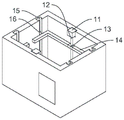
FIG. 2 is a schematic view showing a connecting structure of the squeezee and the crush box;
FIG. 3 is a top view of FIG. 2;
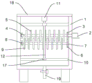
in the figure: the crushing box comprises a crushing box body 1, a first motor body 2, a first gear body 3, a first rotating shaft 4, a first crushing blade 5, a second gear body 6, a connecting shaft 7, a second rotating shaft 8, a second crushing blade 9, a filter screen 10, a second motor body 11, a ball screw 12, a screw slider 13, a scraper 14, a sliding chute 15, a slider 16, a limiting block 17, a box cover 18 and a drain pipe 19.
Detailed Description
The technical solution of the present invention will be described clearly and completely with reference to the accompanying drawings, and obviously, the described embodiments are some, but not all embodiments of the present invention. Based on the embodiments in the present invention, all other embodiments obtained by a person skilled in the art without creative work belong to the protection scope of the present invention.
As shown in fig. 1 to 3, a feed crushing device convenient to clean comprises a crushing box 1 and a box cover 18, wherein a first motor 2 is fixedly arranged on the outer side wall of the crushing box 1, a first gear 3 is fixedly arranged at the output end of the first motor 2, the first gear 3 is meshed with a second gear 6, a first rotating shaft 4 is fixedly arranged on the side wall of the first gear 3 far away from the first motor 2, one end of the first rotating shaft 4 far away from the first gear 3 is rotatably connected with the inner side wall of the crushing box 1, a first crushing blade 5 is fixedly arranged on the first rotating shaft 4, one side wall of the second gear 6 is rotatably connected with the inner side wall of the crushing box 1 through a connecting shaft 7, a second rotating shaft 8 is fixedly arranged on the other side wall of the second gear 6, one end of the second rotating shaft 8 far away from the second gear 6 is rotatably connected with the inner side wall of the crushing box 1, a second crushing blade 9 is fixedly arranged on the second rotating shaft 8, the second crushing blade 9 and the first crushing blade 5 are arranged in a staggered manner, the first motor 2 can drive the first gear 3 and the second gear 6 to rotate after being started, the first gear 3 and the second gear 6 rotate to drive the first rotating shaft 4 and the second rotating shaft 8 to rotate, so that the first crushing blade 5 and the second crushing blade 9 rotate to crush forage, the side wall of the crushing box 1 is symmetrically provided with sliding grooves 15, the sliding grooves 15 are internally provided with sliding blocks 16, the sliding grooves 15 and the sliding blocks 16 are both in a T shape, the positions of the front inner wall and the rear inner wall of the crushing box 1 close to the top end are provided with second motors 11, the output end of each second motor 11 is fixedly provided with a ball screw 12, the bottom end of the ball screw 12 is provided with a limit block 17, the limit block 17 is fixedly connected with the front inner wall and the rear inner wall of the crushing box 1, the ball screw 12 is provided with a screw slide block 13 in a sliding manner, and the side wall of the screw block 13 is fixedly provided with a scraper 14, scraper blade 14 is total four, the symmetry sets up and the structure is the same, scraper blade 14's cross-section all is the L type, scraper blade 14 contradicts with the inner wall of smashing case 1, scraper blade 14 is towards the one side and the slider 16 fixed connection of smashing 1 inner wall of case, start second motor 11, second motor 11 can drive ball screw 12 and rotate, ball screw 12's rotation drives lead screw slider 13 and reciprocates, thereby make scraper blade 14 scrape the forage of smashing 1 inner wall, the fixed filter screen 10 that is equipped with of inner wall of smashing case 1, second crushing blade 9 and first crushing blade 5's top is arranged in to filter screen 10, the moisture that the forage produced at crushing in-process can instil into the bottom of smashing case 1 through filter screen 10, the bottom intercommunication of smashing case 1 is equipped with drain pipe 19, be equipped with the valve on the drain pipe 19.
Working principle, when the utility model is used, forage is added into the crushing box 1 from the top end of the crushing box 1, the first motor 2 is started, the first motor 2 drives the first gear 3 to rotate, the first gear 3 drives the second gear 6 to rotate, the first gear 3 and the second gear 6 drive the first rotating shaft 4 and the second rotating shaft 8 to rotate, the first rotating shaft 4 and the second rotating shaft 8 drive the first crushing blade 5 and the second crushing blade 9 to rotate, so as to crush the forage, water generated by crushing the forage can drip on the bottom end of the crushing box 1 through the filter screen 10 and then is discharged from the drain pipe 19, the forage can be left on the top end of the filter screen 10, the crushed forage can be taken out by opening the forage taking door, the second motor 11 is started, the second motor 11 drives the ball screw 12 to rotate, the ball screw 12 drives the screw slider 13 to move up and down, so as to make the scraper 14 move up and down, the scraper 14 is abutted against the inner wall of the crushing box 1, and the scraper 14 pushes the forage splashed by the inner wall of the crushing box 1 to the top end of the filter screen 10 in the downward moving process, so that the forage on the inner wall of the crushing box 1 is cleaned.
Although embodiments of the present invention have been shown and described, it will be appreciated by those skilled in the art that changes, modifications, substitutions and alterations can be made in these embodiments without departing from the principles and spirit of the invention, the scope of which is defined in the appended claims and their equivalents.
Claims (6)
1. A feed crushing device convenient to clean comprises a crushing box (1) and a box cover (18), and is characterized in that a first motor (2) is fixedly arranged on the outer side wall of the crushing box (1), a first gear (3) is fixedly arranged at the output end of the first motor (2), the first gear (3) is meshed with a second gear (6), a first rotating shaft (4) is fixedly arranged on the side wall of the first gear (3) far away from the first motor (2), one end of the first rotating shaft (4) far away from the first gear (3) is rotatably connected with the inner side wall of the crushing box (1), a first crushing blade (5) is fixedly arranged on the first rotating shaft (4), one side wall of the second gear (6) is rotatably connected with the inner side wall of the crushing box (1) through a connecting shaft (7), and a second rotating shaft (8) is fixedly arranged on the other side wall of the second gear (6), one end of the second rotating shaft (8) far away from the second gear (6) is rotationally connected with the inner side wall of the crushing box (1), a second crushing blade (9) is fixedly arranged on the second rotating shaft (8), sliding grooves (15) are symmetrically arranged on the side wall of the crushing box (1), sliding blocks (16) are arranged in the sliding grooves (15), second motors (11) are arranged at positions, close to the top end, of the front inner wall and the rear inner wall of the crushing box (1), ball screws (12) are fixedly arranged at the output ends of the second motors (11), limiting blocks (17) are arranged at the bottom ends of the ball screws (12), the limiting blocks (17) are fixedly connected with the front inner wall and the rear inner wall of the crushing box (1), screw sliders (13) are arranged on the ball screws (12) in a sliding mode, scraping plates (14) are fixedly arranged on the side walls of the screw sliders (13), and the scraping plates (14) are abutted to the inner wall of the crushing box (1), one surface of the scraper (14) facing the inner wall of the crushing box (1) is fixedly connected with the slide block (16).
2. A feed crushing device convenient for cleaning as claimed in claim 1, characterized in that the second crushing blade (9) is staggered with the first crushing blade (5).
3. The feed crushing device convenient for cleaning as claimed in claim 1, wherein the scraping plates (14) are four in total, are symmetrically arranged and have the same structure, and the sections of the scraping plates (14) are L-shaped.
4. A feed grinder arrangement easy to clean as claimed in claim 1, characterised in that the inner wall of the grinding box (1) is fixedly provided with a sieve (10), the sieve (10) being placed above the second grinding blade (9) and the first grinding blade (5).
5. The feed crushing device convenient for cleaning as claimed in claim 1, wherein the bottom end of the crushing box (1) is communicated with a drain pipe (19), and a valve is arranged on the drain pipe (19).
6. A feed grinder assembly as claimed in claim 1, characterised in that the chute (15) and the slide (16) are T-shaped.
Priority Applications (1)
| Application Number | Priority Date | Filing Date | Title |
|---|---|---|---|
| CN202121366246.2U CN215122292U (en) | 2021-06-18 | 2021-06-18 | Feed crushing device convenient to clean |
Applications Claiming Priority (1)
| Application Number | Priority Date | Filing Date | Title |
|---|---|---|---|
| CN202121366246.2U CN215122292U (en) | 2021-06-18 | 2021-06-18 | Feed crushing device convenient to clean |
Publications (1)
| Publication Number | Publication Date |
|---|---|
| CN215122292U true CN215122292U (en) | 2021-12-14 |
Family
ID=79384599
Family Applications (1)
| Application Number | Title | Priority Date | Filing Date |
|---|---|---|---|
| CN202121366246.2U Active CN215122292U (en) | 2021-06-18 | 2021-06-18 | Feed crushing device convenient to clean |
Country Status (1)
| Country | Link |
|---|---|
| CN (1) | CN215122292U (en) |
Cited By (1)
| Publication number | Priority date | Publication date | Assignee | Title |
|---|---|---|---|---|
| CN114477400A (en) * | 2022-02-11 | 2022-05-13 | 天长市轩之翼电子科技有限公司 | Community recycles device with environment-friendly sewage treatment |
-
2021
- 2021-06-18 CN CN202121366246.2U patent/CN215122292U/en active Active
Cited By (1)
| Publication number | Priority date | Publication date | Assignee | Title |
|---|---|---|---|---|
| CN114477400A (en) * | 2022-02-11 | 2022-05-13 | 天长市轩之翼电子科技有限公司 | Community recycles device with environment-friendly sewage treatment |
Similar Documents
| Publication | Publication Date | Title |
|---|---|---|
| CN215122292U (en) | Feed crushing device convenient to clean | |
| CN108940530B (en) | Mechanical crushing device for traditional Chinese medicine materials | |
| CN115400830A (en) | Grit crushing treatment equipment is used in grit processing | |
| CN211070333U (en) | Food raw material crushing device | |
| CN210474177U (en) | Pulverizer for processing aquatic feed | |
| CN114308332B (en) | Rapeseed oil residue collection device | |
| CN213669568U (en) | Crushing and grinding device capable of avoiding ejection of raw materials under pressure | |
| CN219615735U (en) | Raw material grinding device for protein powder production | |
| CN216910570U (en) | Circulating feeding structure for industrial solid waste treatment | |
| CN219984905U (en) | Fish feed processing reducing mechanism | |
| CN219502901U (en) | Smashing device for recycling anode material | |
| CN215029339U (en) | Domestic small-size agalloch eaglewood milling machine | |
| CN215029286U (en) | Coarse crusher with anti-blocking structure for feeding | |
| CN220386745U (en) | Pulverizer for industrial waste treatment | |
| CN218796323U (en) | Rice milk grinder | |
| CN211988912U (en) | Soybean squeezer with repeated squeezing function | |
| CN219785053U (en) | Crushing mechanism of solid lubricant | |
| CN217699476U (en) | Utilize high-efficient sand mill of centrifugal dynamic separation formula screen cloth | |
| CN217915820U (en) | Raw material crushing device for plywood processing | |
| CN214522159U (en) | Walnut processing spiral oil press with protection casing | |
| CN219424277U (en) | Crushing pulping device | |
| CN213000243U (en) | Waste material high efficiency environmental protection processing apparatus for feed production | |
| CN215312623U (en) | Broken rice reducing mechanism is used in rice processing | |
| CN215087479U (en) | A processing crushing apparatus for health food | |
| CN217615122U (en) | Reducing mechanism is used in raspberry processing |
Legal Events
| Date | Code | Title | Description |
|---|---|---|---|
| GR01 | Patent grant | ||
| GR01 | Patent grant | ||
| TR01 | Transfer of patent right |
Effective date of registration: 20230111 Address after: Room 216, Floor 2, Administrative Committee of Alashankou Comprehensive Bonded Area, Bortala Mongol Autonomous Prefecture, Xinjiang Uygur Autonomous Region, 833400 Patentee after: Alashankou Bojin Biotechnology Co.,Ltd. Address before: 221000 Industrial Avenue South, Shunhe Town, Feng County, Xuzhou City, Jiangsu Province Patentee before: Xuzhou Le Yuan animal husbandry Co.,Ltd. |
|
| TR01 | Transfer of patent right |