CN215104122U - Positioning type clothes airing rod - Google Patents
Positioning type clothes airing rod Download PDFInfo
- Publication number
- CN215104122U CN215104122U CN202120598684.5U CN202120598684U CN215104122U CN 215104122 U CN215104122 U CN 215104122U CN 202120598684 U CN202120598684 U CN 202120598684U CN 215104122 U CN215104122 U CN 215104122U
- Authority
- CN
- China
- Prior art keywords
- clothes
- plate
- connecting plate
- hanging
- block
- Prior art date
- Legal status (The legal status is an assumption and is not a legal conclusion. Google has not performed a legal analysis and makes no representation as to the accuracy of the status listed.)
- Expired - Fee Related
Links
Images

Landscapes
- Drying Of Solid Materials (AREA)
Abstract
本实用新型申请公开了包括导杆和安装在导杆处的若干挂衣模块且挂衣模块与导杆滑动连接,所述若干挂衣模块两两之间通过连接模块连接,所述挂衣模块包括挂环和移动块,所述挂环安装在移动块的底部且移动块与导杆滑动连接,所述相邻的两个挂衣模块的移动块通过连接模块连接;本定位式晾衣杆通过在导杆内安装若干晾挂模块,使得收挂衣物时可将晾挂模块聚拢后再进行衣物的晾挂,便于用户晾挂衣物,节省劳力,同时各挂衣模块通过连接模块两两之间连接,使得挂衣模块能够等距分布,便于衣物的晾干。
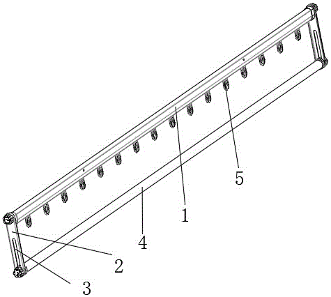
The utility model application discloses a guide rod and a plurality of clothes hanging modules installed at the guide rod, and the clothes hanging modules are slidably connected with the guide rod. The plurality of clothes hanging modules are connected by connecting modules. It includes a hanging ring and a moving block, the hanging ring is installed at the bottom of the moving block and the moving block is slidably connected with the guide rod, and the moving blocks of the two adjacent clothes hanging modules are connected by the connecting module; the positioning type clothes drying rod By installing several hanging modules in the guide rod, the hanging modules can be gathered together before hanging the clothes, which is convenient for users to hang clothes and save labor. The inter-connection enables the clothes hanging modules to be distributed equidistantly, which facilitates the drying of the clothes.
Description
技术领域technical field
本实用新型涉及一种晾衣设备,具体涉及一种定位式晾衣杆。The utility model relates to a clothes drying device, in particular to a positioning type clothes drying rod.
背景技术Background technique
电动晾衣架是安装在室内阳台顶部的一种晾衣设备,现有的智能晾衣架的晾衣杆一般都是一根直杆,使用时直接将挂有衣物的衣架挂在晾衣杆处,但是这种晾衣杆的在晾挂无法将衣物聚拢回收,无需用户来回走动回收衣物,且无法将衣物灯具晾挂,不利于衣物的晾干。The electric clothes drying rack is a kind of clothes drying equipment installed on the top of the indoor balcony. The clothes drying rod of the existing intelligent clothes drying rack is generally a straight rod. However, the clothes drying rod cannot collect and recycle the clothes when it is hanging, without requiring the user to walk back and forth to recover the clothes, and cannot hang the clothes lamps on the air, which is not conducive to the drying of the clothes.
实用新型内容Utility model content
本实用新型意在提供一种定位式晾衣杆。The utility model aims to provide a positioning type clothes drying rod.
为达到以上目的,提供如下方案: 一种定位式晾衣杆,包括导杆和安装在导杆处的若干挂衣模块且挂衣模块与导杆滑动连接,所述若干挂衣模块两两之间通过连接模块连接,所述挂衣模块包括挂环和移动块,所述挂环安装在移动块的底部且移动块与导杆滑动连接,所述相邻的两个挂衣模块的移动块通过连接模块连接。In order to achieve the above purpose, the following solutions are provided: A positioning type clothes drying rod, comprising a guide rod and a plurality of clothes hanging modules installed at the guide rod, and the clothes hanging modules are slidably connected with the guide rod, and the plurality of clothes hanging modules are two by two. They are connected through a connection module. The clothes hanging module includes a hanging ring and a moving block. The hanging ring is installed at the bottom of the moving block and the moving block is slidably connected with the guide rod. The moving blocks of the two adjacent clothes hanging modules Connection via connection module.
进一步,所述移动块远离挂环的一侧设有限位槽,所述限位槽的底部设有卡槽,所述限位槽的上侧设有限位块。Further, a limit groove is provided on the side of the moving block away from the hanging ring, the bottom of the limit groove is provided with a clamping groove, and the upper side of the limit groove is provided with a limit block.
进一步,所述连接模块包括连板、侧板、限位板、导板、顶块和卡块,所述连板的一端端部设有导板,所述导板靠近连板的一侧设有顶块且顶块靠近连板的顶侧,所述连板的另一端的两侧均设有侧板且侧板向连板的顶侧延伸,所述侧板的上设有限位板,所述连板设有侧板的一端的底部设有卡块。Further, the connection module includes a connecting plate, a side plate, a limit plate, a guide plate, a top block and a clamping block, one end of the connecting plate is provided with a guide plate, and a side of the guide plate close to the connecting plate is provided with a top block And the top block is close to the top side of the connecting plate, the two sides of the other end of the connecting plate are provided with side plates and the side plates extend to the top side of the connecting plate, a limit plate is arranged on the side plate, and the connecting plate is The bottom of one end of the plate with the side plate is provided with a clamping block.
进一步,所述卡块与卡槽卡合,所述连板安装在限位槽内,所述侧板位于限位块与限位槽之间且限位板与限位块的侧部相抵,所述连板设有导板的一端安装在与其相邻的一个连接模块的两侧板之间且连板设有导板的一端位于与其相邻的连接模块的连板和与其相邻的挂衣模块的限位块之间,所述连板的顶块和与其相邻的一个移动块上的限位块相抵。Further, the clamping block is engaged with the clamping groove, the connecting plate is installed in the limiting groove, the side plate is located between the limiting block and the limiting groove, and the limiting plate and the side portion of the limiting block are in contact with each other, One end of the connecting plate with the guide plate is installed between the two side plates of a connecting module adjacent to it, and the end of the connecting plate with the guide plate is located on the connecting plate of the connecting module adjacent to it and the clothes hanging module adjacent to it. Between the limit blocks, the top block of the connecting plate is in contact with the limit block on a moving block adjacent to it.
进一步,还包括连接杆和晾杆,所述导杆的端部与连板的端部通过晾杆连接,所述连板上设有安装槽,晾杆安装在安装槽处。Further, it also includes a connecting rod and a drying rod, the end of the guide rod and the end of the connecting plate are connected by the drying rod, the connecting plate is provided with an installation groove, and the drying rod is installed at the installation groove.
本实用新型的工作原理及优点在于:本定位式晾衣杆通过在导杆内安装若干晾挂模块,使得收挂衣物时可将晾挂模块聚拢后再进行衣物的晾挂,便于用户晾挂衣物,节省劳力,同时各挂衣模块通过连接模块两两之间连接,使得挂衣模块能够等距分布,便于衣物的晾干。The working principle and advantages of the utility model are as follows: the positioning type clothes drying rod installs a plurality of drying and hanging modules in the guide rod, so that when the clothes are collected and hung, the drying and hanging modules can be gathered and then the clothes can be hung, which is convenient for users to hang the clothes. Clothes, saving labor, and at the same time, the clothes hanging modules are connected two by two through the connecting modules, so that the clothes hanging modules can be distributed equidistantly, which is convenient for drying the clothes.
附图说明Description of drawings
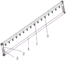
图1为本实用新型的结构示意图;Fig. 1 is the structural representation of the utility model;
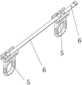
图2为本实用新型挂衣模块和连接模块的结构示意图;Fig. 2 is the structural schematic diagram of the clothes hanging module and the connection module of the present invention;
图3为本实用新型挂衣模块的结构示意图;Fig. 3 is the structural schematic diagram of the clothes hanging module of the present invention;
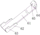
图4为本实用新型连接模块的第一结构图;4 is a first structural diagram of a connection module of the present invention;
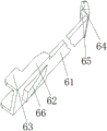
图5为本实用新型连接模块的第二结构图。FIG. 5 is a second structural diagram of the connection module of the present invention.
说明书附图中的附图标记包括:Reference numerals in the drawings in the description include:
1.导杆,2.连接杆,3.安装槽,4.晾杆,5.挂衣模块,51.挂环,52.移动块,53.限位槽,54.卡槽,55.限位块,6.连接模块,61.连板,62.侧板,63.限位板,64.导板,65.顶块,66.卡块。1. Guide rod, 2. Connecting rod, 3. Installation slot, 4. Drying rod, 5. Clothes hanging module, 51. Hanging ring, 52. Moving block, 53. Limit slot, 54. Card slot, 55. Limit Position block, 6. Connection module, 61. Connecting plate, 62. Side plate, 63. Limiting plate, 64. Guide plate, 65. Top block, 66. Card block.
具体实施方式Detailed ways
下面通过具体实施方式进一步详细的说明:The following is a further detailed description through specific embodiments:
如图1至图5所示:一种定位式晾衣杆,包括导杆1和安装在导杆1处的若干挂衣模块5且挂衣模块5与导杆1滑动连接,所述若干挂衣模块5两两之间通过连接模块6连接,所述挂衣模块5包括挂环51和移动块52,所述挂环51安装在移动块52的底部且移动块52与导杆1滑动连接,所述相邻的两个挂衣模块5的移动块52通过连接模块6连接。As shown in Figures 1 to 5: a positioning type clothes drying rod, comprising a
其中,导杆1为基本的安装构件,其用于安装挂衣模块5,导杆1安装在普通支撑架或者电动升降架上,若干个挂衣模块5和连接模块6在导杆1内阵列设置,挂环51用于晾挂衣架。Among them, the
如图3所示,所述移动块52远离挂环51的一侧设有限位槽53,所述限位槽53的底部设有卡槽54,所述限位槽53的上侧设有限位块55。As shown in FIG. 3 , the side of the moving
其中,限位槽53用于安装连接模块6避免连接模块6在活动块上间隙过大,卡槽54用于卡紧连接酶欧快,限位块55用于对连接模块6起运动限制作用。Among them, the
如图4和图5所示,所述连接模块6包括连板61、侧板62、限位板63、导板64、顶块65和卡块66,所述连板61的一端端部设有导板64,所述导板64靠近连板61的一侧设有顶块65且顶块65靠近连板61的顶侧,所述连板61的另一端的两侧均设有侧板62且侧板62向连板61的顶侧延伸,所述侧板62的上设有限位板63,所述连板61设有侧板62的一端的底部设有卡块66。As shown in FIG. 4 and FIG. 5 , the
其中,连板61为薄板状的基本连接件,连板61的一端的两侧均设有侧板62,且侧板62凸出于连板61的顶侧,限位板63为限制连板61运动的机构,连板61另一端的导板64能够避免连板61运动时卡住,顶板对连板61其限位作用。Wherein, the connecting
如图2至图5所示,所述卡块66与卡槽54卡合,所述连板61安装在限位槽53内,所述侧板62位于限位块55与限位槽53之间且限位板63与限位块55的侧部相抵,所述连板61设有导板64的一端安装在与其相邻的一个连接模块6的两侧板62之间且连板61设有导板64的一端位于与其相邻的连接模块6的连板61和与其相邻的挂衣模块5的限位块55之间,所述连板61的顶块65和与其相邻的一个移动块52上的限位块55相抵。As shown in FIG. 2 to FIG. 5 , the
其中,卡块66与卡槽54配合,将连接模块6与挂衣模块5固定在一起,限位槽53用于安装连板61连板61,限位槽53与限位块55协同作用,通过侧板62将连板61相对地限位在活动块上,限位块55还与限位板63协同作用,在各挂衣模块5移动时带动连板61一起运动,晾衣模块能够通过连接模块6带动与其相邻的晾衣模块一起运动,第一晾衣模块上的连板61安装在第二个晾衣模块的限位槽53中,同时第一晾衣模块上的连接模块6的连板61安装在位于第二个晾衣模块的连板61与限位块55之间,安装在第一晾衣模块处的连板61,各晾挂模块通过连接模块6首尾相连,同时各连接模块6也首尾相连。Among them, the
如图1所示,还包括连接杆2和晾杆4,所述导杆1的端部与连板61的端部通过晾杆4连接,所述连板61上设有安装槽3,晾杆4安装在安装槽3处。As shown in FIG. 1 , it also includes a connecting
其中,连接杆2用于连接导杆1和晾杆4,晾杆4用于晾挂衣物,安装槽3使得晾杆4安装在不同的高度上。The connecting
具体实施过程如下:The specific implementation process is as follows:
以两个挂衣模块5之间运动工作过程为例,分别命名成第一挂衣模块5和第二挂衣模块5,安装在两挂衣模块5上的连接模块6分别命名成第一连接模块6和第二连接模块6;当个晾挂模块处于等距铺开的挂衣状态时,若需要将晾挂模块聚拢收挂衣物,只需手动推动最端部的一个晾衣模块即可联动带动其他晾挂模块一起运动聚拢;此过程中,第一晾挂模块的活动块处的卡槽54与连接模块6的连板61底部的卡块66协同作用,推动第一晾挂模块的挂环51运动,挂环51带动将移动块52一起运动,移动块52带导杆1内水平滑动,同时活动块推动连板61在第二晾挂模块的限位槽53中滑动,直至第一连接模块6的连板61大部分堆叠到第二连接模块6的连板61上,第一晾挂模块的活动块与第二晾挂模块的活动块相抵,推动第二晾挂模块一起运动,重复上述过程,即可将所有的晾挂模块推动收拢;当需要将各晾挂模块展开晾挂衣物时,们只需执行上述相反过程即可,前一个连接模块6的连板61上的顶块65运动至与后一个晾挂模块的活动块的限位块55相抵,前一个晾挂模块即可带动后一个晾挂模块展开。Taking the movement process between the two
各晾挂模块和连接可同向设置,即可将各晾挂模块从导杆1的一端收拢至导杆1的另一端;Each hanging module and connection can be arranged in the same direction, that is, each hanging module can be retracted from one end of the
若将各晾挂模块分成两组,对称地设置在导杆1上,即可将各晾挂模块从导杆1的两端向到干的中部聚拢。If the drying and hanging modules are divided into two groups and arranged symmetrically on the
本定位式晾衣杆通过在导杆1内安装若干晾挂模块,使得收挂衣物时可将晾挂模块聚拢后再进行衣物的晾挂,便于用户晾挂衣物,节省劳力,同时各挂衣模块5通过连接模块6两两之间连接,使得挂衣模块5能够等距分布,便于衣物的晾干。The positioning type clothes drying rod installs several drying and hanging modules in the
以上所述仅是本实用新型的实施例,方案中公知的具体结构及特性等常识在此未作过多描述,所属领域普通技术人员知晓申请日或者优先权日之前实用新型所属技术领域所有的普通技术知识,能够获知该领域中所有的现有技术,并且具有应用该日期之前常规实验手段的能力,所属领域普通技术人员可以在本申请给出的启示下,结合自身能力完善并实施本方案,一些典型的公知结构或者公知方法不应当成为所属领域普通技术人员实施本申请的障碍。应当指出,对于本领域的技术人员来说,在不脱离本实用新型结构的前提下,还可以作出若干变形和改进,这些也应该视为本实用新型的保护范围,这些都不会影响本实用新型实施的效果和专利的适用性。本申请要求的保护范围应当以其权利要求的内容为准,说明书中的具体实施方式等记载可以用于解释权利要求的内容。The above are only examples of the present utility model, and common knowledge such as the well-known specific structures and characteristics in the scheme has not been described too much here. Those of ordinary skill in the art know that the utility model belongs to the technical field before the filing date or the priority date. General technical knowledge, be able to know all the prior art in this field, and have the ability to apply conventional experimental means before the date, those of ordinary skill in the art can perfect and implement this scheme in combination with their own abilities under the enlightenment given in this application However, some typical well-known structures or well-known methods should not be obstacles to those skilled in the art from practicing the present application. It should be pointed out that for those skilled in the art, under the premise of not departing from the structure of the present utility model, several deformations and improvements can also be made, which should also be regarded as the protection scope of the present utility model, and these will not affect the present utility model. The effect of the implementation of the new model and the applicability of the patent. The scope of protection claimed in this application should be based on the content of the claims, and the descriptions of the specific implementation manners in the description can be used to interpret the content of the claims.
Claims (5)
Priority Applications (1)
| Application Number | Priority Date | Filing Date | Title |
|---|---|---|---|
| CN202120598684.5U CN215104122U (en) | 2021-03-24 | 2021-03-24 | Positioning type clothes airing rod |
Applications Claiming Priority (1)
| Application Number | Priority Date | Filing Date | Title |
|---|---|---|---|
| CN202120598684.5U CN215104122U (en) | 2021-03-24 | 2021-03-24 | Positioning type clothes airing rod |
Publications (1)
| Publication Number | Publication Date |
|---|---|
| CN215104122U true CN215104122U (en) | 2021-12-10 |
Family
ID=79344656
Family Applications (1)
| Application Number | Title | Priority Date | Filing Date |
|---|---|---|---|
| CN202120598684.5U Expired - Fee Related CN215104122U (en) | 2021-03-24 | 2021-03-24 | Positioning type clothes airing rod |
Country Status (1)
| Country | Link |
|---|---|
| CN (1) | CN215104122U (en) |
Cited By (1)
| Publication number | Priority date | Publication date | Assignee | Title |
|---|---|---|---|---|
| CN115058867A (en) * | 2022-07-18 | 2022-09-16 | 广东好太太科技集团股份有限公司 | A windproof drying rod |
-
2021
- 2021-03-24 CN CN202120598684.5U patent/CN215104122U/en not_active Expired - Fee Related
Cited By (2)
| Publication number | Priority date | Publication date | Assignee | Title |
|---|---|---|---|---|
| CN115058867A (en) * | 2022-07-18 | 2022-09-16 | 广东好太太科技集团股份有限公司 | A windproof drying rod |
| CN115058867B (en) * | 2022-07-18 | 2026-01-23 | 广东好太太科技集团股份有限公司 | Windproof airing rod |
Similar Documents
| Publication | Publication Date | Title |
|---|---|---|
| CN212802148U (en) | Environment-friendly energy-saving waterproof curtain wall | |
| CN111748946A (en) | A dyeing drying device for textile sector | |
| CN208596921U (en) | A kind of cable testing bridge support construction | |
| CN211921996U (en) | Clothes airing device | |
| CN210976201U (en) | Combined dry-hanging ceramic plate convenient to mount | |
| CN215185659U (en) | High-strength light energy-saving bridge convenient to assemble and disassemble | |
| CN104911874A (en) | Intelligent telescopic type clothes drying rack | |
| CN210626256U (en) | Quick-drying testing device for fabric | |
| CN212197257U (en) | Hanging mechanism convenient for clothing production and capable of taking off clothing | |
| CN218832494U (en) | Hanging device for T-shirt | |
| CN221652504U (en) | Photovoltaic panel device with clothes drying function | |
| CN219965450U (en) | Joint gluing device for wire harness production | |
| CN217938250U (en) | Nucleic acid collecting rack | |
| CN221526731U (en) | Sectional type heating and ventilation radiator | |
| CN214450674U (en) | ETC fixes a position intelligent terminal installation mechanism | |
| CN206245084U (en) | A kind of Multifunctional clothes airing rack device | |
| CN213151553U (en) | Electric wire sleeve connector for big data machine room | |
| CN222028127U (en) | Detection device for air permeability of fabric | |
| CN219875631U (en) | Parallel installation frame for photovoltaic power generation plates | |
| CN223415753U (en) | A hanging device for garment processing | |
| CN220471950U (en) | A ground source heat pump system operating parameter monitoring device | |
| CN209321958U (en) | Glassware automatic material clamping device for discharging | |
| CN222087319U (en) | A physical performance testing device for building energy-saving doors and windows | |
| CN215842103U (en) | A normal temperature dust bag | |
| CN213868459U (en) | Positioning connecting piece for building curtain wall engineering |
Legal Events
| Date | Code | Title | Description |
|---|---|---|---|
| GR01 | Patent grant | ||
| GR01 | Patent grant | ||
| CF01 | Termination of patent right due to non-payment of annual fee |
Granted publication date: 20211210 |
|
| CF01 | Termination of patent right due to non-payment of annual fee |