High-speed leaf cutter
Technical Field
The utility model relates to a mulberry leaf cutting technical field, concretely relates to high-speed leaf cutter.
Background
At present, in the process of silkworm breeding, in the process of quantitatively feeding young silkworms with mulberry leaves or manufacturing mulberry leaf tea, the mulberry leaves are cut into small strips with uniform and small sizes, particularly in the process of preparing young silkworm feeding materials, the mulberry leaves can be preferably cut into small strips with basically the same sizes and small distribution difference of leaf veins, the proper young silkworm feeding materials can be obtained only by improving the cutting effect, and in addition, the improvement of the mulberry leaf cutting efficiency is also very important.
In conclusion, the existing mulberry leaf cutting machine has the defects of unstable structure, low cutting efficiency, difficulty in maintaining and replacing accessories and the like, and needs to be further improved.
SUMMERY OF THE UTILITY MODEL
Therefore, the utility model provides a high-speed leaf cutter.
In order to achieve the above object, the present invention provides the following technical solutions:
the utility model provides a high-speed leaf cutter, which comprises a feeding device, a cutting device and a driving device, wherein the feeding device is connected with the cutting device, and the driving device drives the feeding device and the cutting device;
the cutting device comprises a pressing cutting mechanism and a rotary cutter cutting mechanism connected with the pressing cutting mechanism;
the pressing and cutting mechanism comprises a hob and a pressing shaft matched with the hob, and the hob is in clearance fit with the pressing shaft and cuts blades entering the pressing and cutting mechanism.
Preferably, the rotary cutter cutting mechanism comprises a rotary cutter and a fixed cutter matched with the rotary cutter, the fixed cutter is arranged at a discharge port of the pressing and cutting mechanism, and the rotary cutter and the fixed cutter form a cutting port in the rotating process to cut the pressed and cut blade.
Preferably, the feeding device comprises a conveying belt and a nip roll, the nip roll is arranged at the feeding port, and the nip roll is arranged at the front end of the pressing and cutting mechanism.
Preferably, the driving means drives the motor, the driving gear, the first and second driven gears engaged with the driving gear, the third driven gear engaged with the first driven gear, and the fourth driven gear engaged with the second driven gear;
the first driven gear is connected with one end of the pressing shaft and drives the pressing shaft to rotate;
the second driven gear is connected with one end of the main rotating shaft of the conveying belt and drives the conveying belt to run;
the third driven gear is connected with one end of the rotary shaft of the hob and drives the hob to rotate;
and the fourth driven gear is connected with one end of the rotating shaft of the nip roll and drives the nip roll to rotate.
Preferably, the surface of the nip roll is provided with anti-slip lines.
Preferably, the output end of the driving motor is connected with a first belt pulley on the transmission shaft of the driving gear through a first belt, and is connected with a second belt pulley on the rotating shaft of the rotating knife through a second belt.
Preferably, the rotary knife includes a rotating shaft and a cutting blade disposed in a circumferential direction of the rotating shaft and parallel to the rotating shaft.
Preferably, a baffle is arranged between the pressing and cutting mechanism and the rotary cutter cutting mechanism.
Preferably, a cover plate is arranged on the blanking device.
Preferably, the high-speed leaf cutter further comprises a fixing frame, and the feeding device, the cutting device and the driving device are all mounted on the fixing frame.
The utility model has the advantages of as follows:
the high-speed leaf cutter of the utility model can cut the leaves into blocks at one time, the surface of the leaves can not be damaged in the cutting process, and the cutting amount of the mulberry leaves can reach 500kg/h, thereby greatly improving the production efficiency and saving labor; meanwhile, the hob and the rotary cutter are convenient to disassemble and convenient to install and maintain.
Drawings
In order to more clearly illustrate the embodiments of the present invention or the technical solutions in the prior art, the drawings used in the description of the embodiments or the prior art will be briefly described below. It should be apparent that the drawings in the following description are merely exemplary, and that other embodiments can be derived from the drawings provided by those of ordinary skill in the art without inventive effort.
The structure, ratio, size and the like shown in the present specification are only used for matching with the content disclosed in the specification, so as to be known and read by people familiar with the technology, and are not used for limiting the limit conditions which can be implemented by the present invention, so that the present invention has no technical essential significance, and any structure modification, ratio relationship change or size adjustment should still fall within the scope which can be covered by the technical content disclosed by the present invention without affecting the efficacy and the achievable purpose of the present invention.
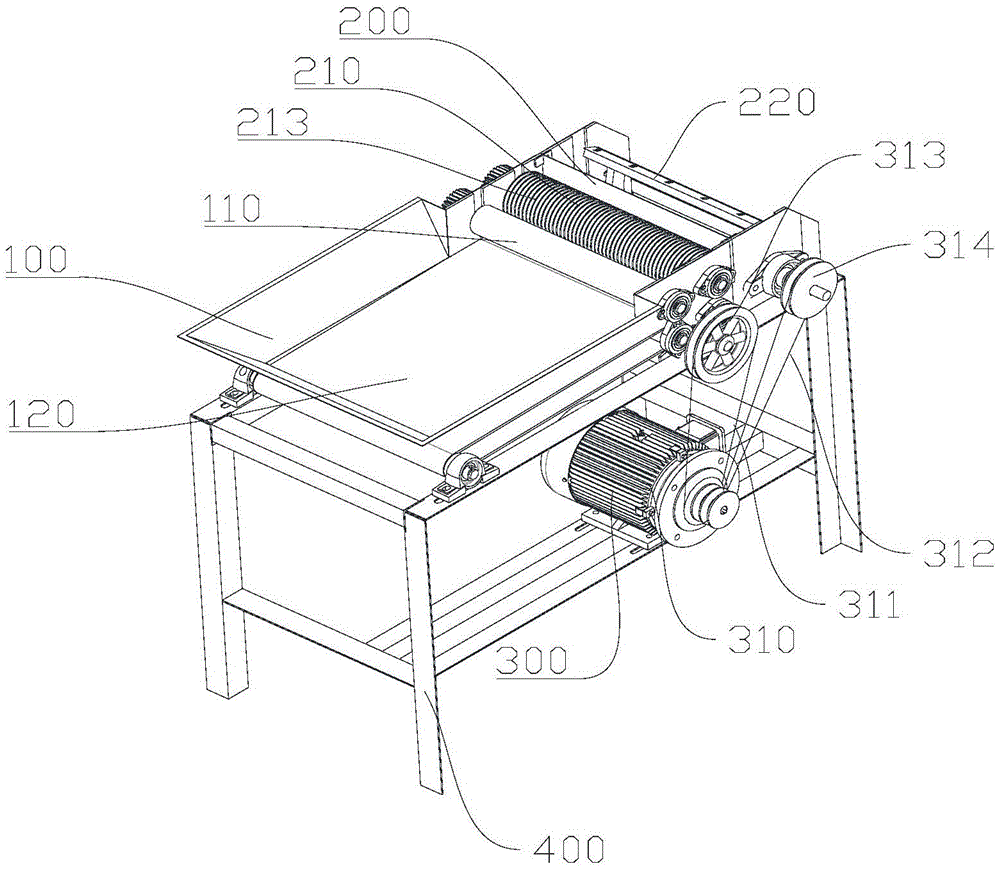
Fig. 1 is a schematic structural view of a high-speed leaf cutter provided in an embodiment of the present invention;
fig. 2 is a schematic structural diagram of a high-speed leaf cutter according to another embodiment of the present invention;
fig. 3 is a schematic structural diagram of a feeding device and a pressing and blanking mechanism provided in an embodiment of the present invention;
fig. 4 is a schematic structural view of a rotary knife according to an embodiment of the present invention;
fig. 5 is a schematic structural view of a material-pressing-and-fitting mechanism provided in the embodiment of the present invention;
in the figure: 100-a feeding device; 110-nip rolls; 120-a conveyor belt; 200-a cutting device; 210-a pressing and cutting mechanism; 211-baffles; 212-pressing the shaft; 213-hob cutter; 220-a rotary cutter cutting mechanism; 221-fixed cutter; 222-rotating knife rotating shaft; 223-fixing columns; 224-a cutting blade; 300-a drive device; 310-a drive motor; 311-a first belt; 312-a second belt; 313-a first pulley; 314-a second pulley; 320-a drive gear; 321-a first driven gear; 322-a second driven gear; 323-a third driven gear; 324-a fourth driven gear; 400-fixing frame.
Detailed Description
The present invention is described in terms of specific embodiments, and other advantages and benefits of the present invention will become apparent to those skilled in the art from the following disclosure. Based on the embodiments in the present invention, all other embodiments obtained by a person skilled in the art without creative work belong to the protection scope of the present invention.
As shown in fig. 1, fig. 2 and fig. 5, the present invention provides a high-speed leaf cutter, which comprises a feeding device 100, a material cutting device 200 and a driving device 300, wherein the feeding device 100 is connected with the material cutting device 200, and the driving device 300 drives the feeding device 100 and the material cutting device 200; the cutting device 200 comprises a pressing and cutting mechanism 210 and a rotary cutter cutting mechanism 220 connected with the pressing and cutting mechanism 210; the pressing and cutting mechanism 210 includes a roller cutter 213 and a pressing shaft 212 engaged with the roller cutter 213, the roller cutter 213 and the pressing shaft 212 are in clearance fit to cut the blade entering the pressing and cutting mechanism 210, and the roller cutter 213 is a cylindrical roller cutter 213 formed by a plurality of annular blades at certain intervals. Specifically, the last rubber tube last shaft 212 that establishes of last shaft 212, the parcel has the rubber coating in its shaft 212's the axis of rotation, hobbing cutter 213 is located the top, and shaft 212 is located the below, and the marginal end of hobbing cutter 213's blade is impressed in the rubber coating, forms the cutting opening between shaft 212 and hobbing cutter 213 like this, can cut into the strip material with the material, and the surface that has shaft 212 is equipped with the rubber tube, and its material is softer, has avoided at the in-process of cutting the material, harms the blade.
In an alternative embodiment, the pressing shaft 212 is provided with a plurality of protrusions at intervals which are in clearance fit with the blades of the hob 213 and grooves which are in fit with the hob 213, and the hob and the pressing shaft are matched to cut the blade material.
As shown in fig. 3 and 4, the rotary cutter material cutting mechanism 220 includes a rotary cutter and a stationary cutter 221 engaged with the rotary cutter, the stationary cutter 221 is disposed at the discharge port of the pressing material cutting mechanism 210, and the rotary cutter and the stationary cutter 221 form a cutting port in the rotating process to cut the pressed and cut blade. The rotary knife includes a rotary knife rotating shaft 222 and cutting blades 224 disposed in the circumferential direction of the rotating shaft and parallel to the rotating shaft, the cutting blades 224 can be fixed to the rotating shaft through fixing posts 223, the rectangular stationary knife 221 and the rectangular rotating cutting blades 224 can rapidly cut the material, and preferably, the number of the cutting blades 224 is 3.
The feeding device 100 comprises a conveying belt 120 and a nip roll 110, the nip roll 110 is located above the conveying belt 120 and is close to one end of a feeding port, materials to be cut, such as mulberry leaves, are placed on the conveying belt 120 at the front end of the pressing and cutting mechanism 210, the conveying belt 120 conveys the materials to the feeding port, the materials are pressed evenly under the action of the nip roll 110, the pressed and evenly pressed materials are sequentially cut into strip-shaped materials through the pressing and cutting mechanism 210, and the strip-shaped materials are cut through the rotary cutter cutting mechanism 220 to form block-shaped materials. Preferably, the surface of the pressure roller 110 is provided with anti-slip patterns, and the anti-slip patterns can contact with the material, so as to increase the friction between the anti-slip wheel and the material, thereby facilitating the material to be conveyed to the pressing and material cutting mechanism 210.
The driving device 300 includes a driving motor 310, a driving gear 320, first and second driven gears 321 and 322 engaged with the driving gear 320, a third driven gear 323 engaged with the first driven gear 321, and a fourth driven gear 324 engaged with the second driven gear 322; the first driven gear 321 is connected with one end of the pressure shaft 212 to drive the pressure shaft 212 to rotate; the second driven gear 322 is connected with one end of the main rotating shaft of the conveying belt 120 to drive the conveying belt 120 to run, and the other end of the conveying belt 120 is provided with a driven rotating shaft; the third driven gear 323 is connected with one end of the rotating shaft of the hob 213 to drive the hob 213 to rotate; the fourth driven gear 324 is connected to one end of the rotational shaft of the nip roll 110, and drives the nip roll 110 to rotate. The driving gear 320, the first driven gear 321, the second driven gear 322, the third driven gear 323 and the fourth driven gear 324 are all disposed on the same side.
The output end of the driving motor 310 is connected to a first belt pulley 313 on the transmission shaft of the driving gear 320 through a first belt 311, and the belt pulley is driven to rotate by the belt, so that the driving gear 320 rotates during the rotation of the belt pulley. The output end of the driving motor 310 is further connected to a second belt pulley 314 on the rotating shaft of the rotary knife through a second belt 312, so as to drive the rotary knife to rotate, thereby realizing the cutting of the rotary knife and the fixed knife 221 to the material. The output end of the driving motor 310, the first pulley 313 and the second pulley 314 are disposed on the same side.
A baffle 211 is arranged between the pressing and cutting mechanism 210 and the rotary cutter cutting mechanism 220, a discharge hole of the pressing and cutting mechanism 210 is formed between the bottom of the baffle 211 and the fixed cutter 221, the material cut by the pressing and cutting mechanism 210 is rotary cut by the rotary cutter cutting mechanism 220 after passing through the discharge hole, and the cut material is output by the discharge hole arranged at the lower part of the rotary cutter cutting mechanism 220 after the rotary cutter cutting mechanism 220 is rotary cut.
The blanking device 200 is provided with a cover plate, a feed inlet is formed between the cover plate and the conveyor belt 120, and the material entering through the feed inlet is pressed uniformly by the pressure roller 110 and then enters the pressing blanking mechanism 210 and the rotary cutter blanking mechanism 220 for cutting.
The utility model discloses a high-speed leaf cutter still includes mount 400, and feed arrangement 100, blank device 200 and drive arrangement 300 are all installed mount 400 upper end, it is concrete, feed arrangement 100 sets up the one end at mount 400, and blank device 200 is connected the back with feed arrangement 100, is located the other end of mount 400, and drive arrangement 300 installs the bottom at mount 400.
The utility model discloses a high-speed cut leaf machine's theory of operation does: the power switch is turned on, the driving motor 310 is turned on, the output end of the driving motor 310 drives the first belt pulley 313 and the second belt pulley 314 to rotate, the first belt pulley 313 drives the driving gear 320 to rotate through the transmission shaft, the driving gear 320 drives the first driven gear 321 and the second driven gear 322 to rotate, the first driven gear 321 drives the third driven gear 323 to rotate, and the second driven gear 322 drives the fourth driven gear 324 to rotate. In this way, the driving device 300 realizes the operations of driving the conveyer belt 120 to operate, driving the nip roll 110 to rotate, driving the hob 213 to rotate for cutting, and driving the hob to rotate for cutting, thereby realizing the rapid cutting of the material.
Although the invention has been described in detail with respect to the general description and the specific embodiments, it will be apparent to those skilled in the art that modifications and improvements can be made based on the invention. Therefore, such modifications and improvements are intended to be within the scope of the invention as claimed.