CN215089695U - Wet garbage biochemical decrement treatment system - Google Patents
Wet garbage biochemical decrement treatment system Download PDFInfo
- Publication number
- CN215089695U CN215089695U CN202120535150.8U CN202120535150U CN215089695U CN 215089695 U CN215089695 U CN 215089695U CN 202120535150 U CN202120535150 U CN 202120535150U CN 215089695 U CN215089695 U CN 215089695U
- Authority
- CN
- China
- Prior art keywords
- biochemical
- bin
- garbage
- frame
- extrusion
- Prior art date
- Legal status (The legal status is an assumption and is not a legal conclusion. Google has not performed a legal analysis and makes no representation as to the accuracy of the status listed.)
- Active
Links
Images





Landscapes
- Processing Of Solid Wastes (AREA)
Abstract
The utility model discloses a wet rubbish biochemical decrement processing system. The system comprises a wet garbage feeding device, a pretreatment module, a biochemical treatment module and an electrical control system; the wet garbage feeding device comprises a garbage can lifter and a sorting pool; the pretreatment module is formed by directly connecting a double-shaft shredder and an extrusion dehydrator; the biochemical treatment module comprises a biochemical bin; the sorting pool is arranged above the pretreatment module; a wet garbage discharge port at the bottom of the sorting tank is positioned right above a feed port of the double-shaft shredder; the discharge port of the double-shaft shredder is directly connected with the feed inlet of the extrusion dehydrator; the extrusion dehydrator is installed at a certain inclination angle with the horizontal plane, the discharge port of the extrusion dehydrator is directly connected with the biochemical bin inlet of the biochemical treatment module, and solid filter residues after being squeezed and dehydrated by the extrusion dehydrator directly enter the biochemical bin for microbial degradation, so that reduction and recycling are realized. The wet garbage treatment system has the characteristics of high integration level, low energy consumption, capacity of realizing biochemical decrement recycling and the like.
Description
Technical Field
The utility model belongs to the technical field of wet refuse treatment, a biochemical decrement processing system of wet rubbish is related to.
Background
After being discarded, the wet garbage is easy to deteriorate and rot in natural environment and breed mosquitoes and flies; the leachate and the generated waste gas pollute the water body and the atmosphere. With the increasing requirements on environmental protection, the on-site treatment of the wet garbage becomes a mainstream solution for harmlessness and recycling of the wet garbage.
At present, biochemical decrement equipment is often dispersedly arranged, the occupied area is large, intermediate transition links are many, and the pipeline laying is complex; the degradation work efficiency of normal temperature strains is generally lower than that of high temperature strains, and the problem of overhigh energy consumption of the high temperature strains is solved due to the required temperature environment.
SUMMERY OF THE UTILITY MODEL
An object of the utility model is to overcome the not enough of prior art, provide a wet rubbish biochemical decrement processing system that the integrated level is high, the energy consumption is low, can realize biochemical decrement resourceization.
The utility model aims at realizing through the following technical scheme:
the utility model relates to a wet garbage biochemical decrement treatment system, which comprises a wet garbage feeding device, a pretreatment module, a biochemical treatment module and an electrical control system connected with the pretreatment module, the biochemical treatment module and the wet garbage feeding device; the wet garbage feeding device mainly comprises a garbage can lifter and a sorting pool; the pretreatment module is formed by directly connecting a double-shaft shredder and an extrusion dehydrator; the biochemical treatment module mainly comprises a biochemical bin; the sorting pool is arranged above the pretreatment module; a wet garbage discharge port is formed in the bottom of the sorting tank, the wet garbage discharge port of the sorting tank is positioned right above a feed port of the double-shaft shredder, and manually sorted wet garbage materials directly enter the feed port of the double-shaft shredder; the discharge port of the double-shaft shredder is directly connected with the feed inlet of the extrusion dehydrator; the extrusion dehydrator is arranged at a certain inclination angle with the horizontal plane, a discharge port of the extrusion dehydrator, namely a filter residue discharge port, is directly connected with an inlet of a biochemical treatment module, and filter residue discharge of the extrusion dehydrator directly enters the biochemical treatment module; a garbage can clamping frame is arranged at the bottom of the garbage can lifter; the garbage bin lifting machine has a promotion pneumatic cylinder, and this promotion pneumatic cylinder can with garbage bin jack-up on the garbage bin clamping frame, rise, upset, empty to letter sorting pond.
Further, a heat-conducting oil bin is arranged at the bottom of the biochemical bin; a heating component is arranged at the bottom in the heat-conducting oil bin; a mesh plate is arranged at the bottom of the sorting pool; a wet garbage discharge port is arranged on one side of the mesh plate at the bottom of the sorting pool; the other side below the mesh plate at the bottom of the sorting tank is provided with a percolate tank, and the bottom of the percolate tank is provided with a waste liquid outlet.
Furthermore, the heating components are electric heating tube sets, and two groups of heating components are arranged at certain intervals; in the heating stage, two groups of heating assemblies operate simultaneously; and in the heat preservation stage, the two groups of heating assemblies operate in turn and are opened and closed circularly.
Furthermore, a plurality of air inlets are arranged on the side wall of the biochemical bin, and duckbill check valves are arranged at the air inlets; the exhaust outlet at the top of the biochemical bin is connected with a deodorization device.
Further, a bin temperature transmitting meter is arranged in the biochemical bin; the high and low positions in the heat-conducting oil bin are respectively provided with an oil bin temperature transmitting meter. The oil bin temperature transmitting meter adopts high and low arrangement, and oil temperature monitoring and oil bin liquid level change are both considered.
Furthermore, a stirring shaft is arranged in the biochemical bin, the stirring shaft transversely penetrates through the biochemical bin, and one end of the stirring shaft is connected with a stirring motor outside the biochemical bin.
Furthermore, the garbage can hoister comprises a base guide rail, a clamping frame, a lifting frame, a turnover frame, a hydraulic cylinder, a chain wheel set, a chain, a hinge shaft and a connecting piece; the bottom of the hydraulic cylinder is arranged on a base guide rail of a non-moving part, the top of a push rod of the hydraulic cylinder is provided with a chain wheel group, a chain is hung on the chain wheel, one end of the chain is connected with the roll-over stand, the other end of the chain is arranged on a connecting piece, and the connecting piece is fixed on the base guide rail through a feeding weighing sensor; the pair of guide wheel sets I arranged on the lifting frame and the pair of guide wheel sets II arranged on the overturning frame are embedded in the guide grooves of the base guide rail, so that moving components such as the clamping frame, the lifting frame, the overturning frame and the like can move along the base guide rail; a pair of third guide wheel sets are arranged on the clamping frame, and the third guide wheel sets and the whole clamping frame are embedded into the guide grooves of the lifting frame together and can move up and down along the grooves; the turnover frame is connected with the clamping frame through a hinge shaft, and the turnover frame and the clamping frame perform relative turnover motion around a shaft under the action of the tension of the chain; the reset spring is connected with the turnover frame and the clamping frame and mainly provides restoring force for resetting of the turnover frame and the clamping frame in the descending process.
Furthermore, the extrusion dehydrator comprises a frame, a speed reduction motor, an extrusion screw shaft, a bearing seat, a feeding screen drum, a deep dehydration section filter drum, a back pressure plate, a back pressure spring and a locking nut; the speed reducing motor is arranged on the frame, one end of the extrusion screw shaft is connected to the speed reducing motor, and the other end of the extrusion screw shaft is arranged on a bearing seat near a discharge port on the frame; wherein, the spiral part of the extrusion spiral shaft is of a sectional structure, the rear section (feeding section), namely one end close to the feeding, is a large-pitch section and penetrates through the feeding screen drum, and the feeding hole is arranged on the feeding screen drum; the front section (deep dehydration section) is close to the discharge end and is a small pitch gradual change section, a group of double helix blade groups consisting of two single helix blades welded on the helix shaft in a staggered way of 180 degrees are arranged at regular intervals, and the double helix blade groups penetrate through the depth dehydration section filter cylinder; the front end of the spiral part is provided with a discharge hole arranged on the frame and a back pressure plate capable of freely sliding along the shaft; one end of the back pressure spring is propped against the back pressure plate, and the other end of the back pressure spring is propped against the locking nut.
Furthermore, the filter cylinder of the deep dehydration section consists of two semicircular spliced filter-pressing screen cylinders and a pair of auxiliary extrusion inserting plates; the auxiliary extrusion inserting plate is arranged between the filter pressing screen cylinder and the extrusion screw shaft, and the gear shaping of the auxiliary extrusion inserting plate extends into the space between two adjacent double-spiral blade groups of the screw shaft, so that the material can be further shredded, the discharged material particles are finer, and the reduction and volume reduction effects are improved.
Furthermore, the extrusion dehydrator is arranged at an included angle of 30 degrees with the horizontal plane; a forced scraping rod with adjustable length is arranged at the discharge port of the extrusion dehydrator; the flange of the discharge port of the extrusion dehydrator is arranged on the side wall of the biochemical bin body of the biochemical treatment module, and the filter residue discharge of the extrusion dehydrator directly enters the biochemical bin.
The utility model discloses a biochemical decrement processing system of wet rubbish, it is the wet rubbish decrement resourceful system of small-size intelligence, and the modularization equipment, the integrated level is high, has functions such as material breakage, dehydration, organic matter degradation resourceization, data collection.
The wet garbage treatment method by utilizing the wet garbage biochemical decrement treatment system of the utility model comprises the following steps: pushing the standard garbage can filled with wet garbage to a garbage can clamping frame at the bottom of a garbage can lifting machine, and operating a button box to inching control locking, loading lifting (counting and weighing are completed in the loading process), overturning and dumping to a sorting pool; after being manually sorted in the sorting pond, the wet garbage materials enter a crushing module; a double-shaft shredder in the crushing module crushes the wet garbage materials into small particles, and then the small particles enter a feeding port of a directly-connected extrusion dehydrator to perform next material dehydration; the extrusion dehydrator adopts a screw extrusion process to carry out solid-liquid separation; the solid filter residue after being squeezed and dewatered by the squeezing and dewatering machine is discharged from a filter residue discharge port at the front end of the filter residue and enters a biochemical bin of a biochemical treatment module for microbial degradation (organic matter decomposition by microorganisms), so that reduction and recycling are realized, and the squeezed filtrate can be recycled together with the waste liquid after being sorted by the sorting pond and enters a filtrate treatment system (optional).
The utility model has the advantages that:
the utility model provides a small intelligent wet garbage biochemical decrement recycling system, which has the characteristics of high integration, low energy consumption, no peculiar smell, discharging recycling and the like, can automatically lift, crush, squeeze and dewater wet garbage materials and decompose microorganisms, realizes about 90 percent decrement, and reduces clearing and treatment pressure; in the treatment process, wet garbage materials are converted into organic fertilizers, so that resource recovery is realized, the treatment working conditions of landfills and incineration plants are improved, and secondary pollution such as leachate and methane is reduced.
The utility model discloses a biochemical decrement processing system of wet rubbish adopts high temperature bacterial process route to handle wet rubbish, collects breakage, extrusion dehydration, organic matter degradation resourceful function in an organic whole, and it mainly has following characteristics:
1. the integration level is high, the functions of crushing and dehydration pretreatment are integrated inside, and the direct feeding of wet garbage and organic garbage can be realized;
2. the low-speed treatment process has low equipment operation noise;
3. all functional parts are directly connected, no redundant link is provided, and the equipment volume and the occupied area are small;
4. the working mode of the heating assembly is reasonably controlled, and the power consumption is reduced.
Drawings
FIG. 1 is a system diagram of a biochemical decrement treatment system for wet garbage according to the present invention;
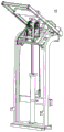
FIG. 2 is a schematic view of the general structure of the L-shaped arrangement of the wet waste biochemical reduction treatment system of the present invention;
FIG. 3 is a flow chart of the operation of the wet waste biochemical abatement system of the present invention;
FIG. 4 is a schematic view of the biochemical treatment module 4 of the wet garbage biochemical decrement treatment system according to the present invention;
FIG. 5 is a schematic side view of the biochemical treatment module 4 of the wet waste biochemical reduction treatment system according to the present invention;
FIG. 6 is a schematic view of the feedback portion of the electrical control system of the wet waste biochemical abatement system of the present invention;
fig. 7 is a schematic structural view of the extrusion dehydrator 7 according to the present invention;
fig. 8 is a schematic view of a partially enlarged structure of a front section of the extrusion dehydrator 7 according to the present invention;
fig. 9 is a schematic structural view of the back pressure plate 18 of the extrusion dehydrator 7 according to the present invention;
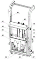
fig. 10(a) and 10(b) are schematic structural diagrams of the trash can elevator 1 according to the present invention in the forward and reverse directions;
fig. 10(c) and 10(d) are schematic diagrams of the front and back directions of the first guide wheel set 49 of the garbage can hoist 1 reaching the top end of the arc part of the base guide rail 41;
fig. 10(e) is a schematic diagram of the garbage can elevator 1 according to the present invention, in which the third guide wheel set 47 rises to form a triangle with the first guide wheel set 49 and the hinge shaft 50.
In the figure: 1. the device comprises a garbage can lifter 2, a sorting pool 3, a pretreatment module 4, a biochemical treatment module 5, a garbage can 6, a double-shaft shredder 7, an extrusion dehydrator 8, an electric heating pipe group A9, an electric heating pipe group B10, a stirring motor 11, a stirring shaft 12, a deodorization device 13, a biochemical bin 14, a heat-conducting oil bin 15, a speed reduction motor 16, an extrusion screw shaft 17, a filter pressing screen drum 18, a back pressure plate 19, a back pressure spring 20, a locking nut 21, an auxiliary extrusion inserting plate 22, a feed inlet 23, a liquid collecting tank 24, a rack 25, a feed screen drum 26, a bearing seat 27, a discharge outlet 28, a forced scraping rod 29, a lower limiting sensor 30 of the lifter, an upper limiting sensor 31 of the lifter, a feeding weighing sensor 32, a bin temperature transmitting meter 33, an oil bin temperature transmitting meter 35, a filter residue discharge outlet 36, Filtrate outlet 37, conical welding piece 38, bushing 41, base guide rail 40, clamping frame 42, lifting frame 43, roll-over stand 44, hydraulic cylinder 45, chain wheel set 46, chain 47, guide wheel set three 48, guide wheel set two 49, guide wheel set one 50, hinge shaft 51, connecting piece 52, return spring A, material conveying direction 60, duckbilled check valve 61, wet garbage discharge port 62, mesh plate 63, percolate groove
Detailed Description
The present invention will be further described with reference to the accompanying drawings and examples.
Examples
As shown in fig. 1, the utility model relates to a wet garbage biochemical decrement treatment system, namely a small intelligent wet garbage decrement recycling system, which comprises a wet garbage feeding device, a pretreatment module 3, a biochemical treatment module 4 and an electrical control system; the system is assembled in a modularized way, has high integration level, and has the functions of crushing materials, dehydrating, degrading and recycling organic matters, collecting data and the like; the wet garbage feeding device mainly comprises a garbage can elevator 1 and a sorting pool 2; the pretreatment module 3 mainly comprises a double-shaft shredder 6 and an extruding dehydrator 7; the biochemical treatment module 4 mainly comprises a biochemical bin 13; the sorting pond 2 is arranged above the pretreatment module 3; the bottom of the sorting pool 2 is provided with a mesh plate 62 for percolating the waste liquid in the material; one side below the mesh plate 62 at the bottom of the sorting pool 2 is connected with a percolate groove 63, and the bottom of the percolate groove 63 is provided with a waste liquid discharge port which is connected with a filtrate treatment system; the other side of the mesh plate 62 at the bottom of the sorting pond 2 is provided with a wet garbage discharge port 61, and the wet garbage discharge port 61 is also the feed port of the double-shaft shredder 6; that is, the wet garbage discharge port of the sorting pond 2 is positioned right above the feed port of the double-shaft shredder 6, and the wet garbage materials after manual sorting directly enter the feed port of the double-shaft shredder 6; the discharge port of the double-shaft shredder 6 is directly connected with the feed inlet of the extruding dehydrator 7; the discharge port of the extrusion dewaterer 7, namely the filter residue discharge port, is directly connected with the inlet of the biochemical bin 13 of the biochemical treatment module 4 (the flange of the filter residue discharge port of the extrusion dewaterer 7 is arranged on the side wall of the bin body of the biochemical bin 13 of the biochemical treatment module 4). The pretreatment module 3 is formed by directly connecting a double-shaft shredder 6 and an extrusion dehydrator 7, the extrusion dehydrator 7 is arranged at an included angle of 30 degrees with the horizontal plane, and filter residue discharged by the extrusion dehydrator 7 directly enters a biochemical bin 13. The bottom of the garbage can lifter 1 is provided with a garbage can clamping frame 40; the garbage can lifter 1 is provided with a lifting hydraulic cylinder which can jack up, lift, overturn and dump the garbage can 5 on the garbage can clamping frame 40 to the sorting pool 2.
In the biochemical decrement treatment system for wet garbage, the wet garbage feeding device, the pretreatment module 3 and the biochemical treatment module 4 form a mechanical structure part of the equipment; the electrical control system is connected with the pretreatment module 3, the biochemical treatment module 4 and the wet garbage feeding device; the electric control system mainly comprises a driving part, a feedback part and an operation part; the electric control system mainly controls all driving motors on the equipment, and an operator can manually or automatically operate the equipment through the operation box/human-computer interface.
The bottom of the biochemical bin 13 is provided with a heat-conducting oil bin 14; and a heating component (two groups of electric heating pipe groups 8 and 9) is arranged at the bottom in the heat-conducting oil bin 14. The heating components (the electric heating pipe groups 8 and 9) are arranged at the bottom of the heat conduction oil bin 14 and are divided into two groups, the heating components are arranged at certain intervals, the heating stages run simultaneously, and the heat preservation stages are opened and closed in turn and in a circulating mode.
A bin temperature transmitting meter 32 is arranged in the biochemical bin 13; four air inlets are arranged at the upper part of the side wall of the biochemical bin 13, and duckbill check valves 60 are arranged at the air inlets; the top exhaust outlet of the biochemical bin 13 is connected with the deodorization device 12.
An oil bin temperature transmitting meter 33 is arranged in the heat-conducting oil bin 14; the oil bin temperature transmitting meter 33 is arranged in a high-low mode (the oil bin temperature transmitting meter 33 is arranged at each of the high position and the low position), and oil temperature monitoring and oil bin liquid level change are both considered.
As shown in fig. 2, the garbage can elevator 1 and the sorting pond 2 constitute the wet garbage feeding device, wherein the sorting pond 2 is arranged above the pretreatment module 3; the pretreatment module 3 is connected with the biochemical treatment module 4 to form an L-shaped assembly structure. The occupied area of the equipment is small, the assembled area is less than 3900 multiplied by 3600(mm), and an underground cache pool is not required to be dug; the operation height is less than 3000mm, the device can be widely applied to the internal space of a small garbage room, and is applied to the on-site reduction and resource treatment of organic garbage in communities and rural areas.
The biochemical treatment module 4 is schematically shown in fig. 4 and 5. The biochemical treatment module 4 comprises a biochemical bin 13 and a heat conduction oil bin 14; the biochemical bin 13 is a place for degrading and recycling wet garbage organic materials, and after the discharge of the extrusion dehydrator 7 enters the biochemical bin 13, organic matters are degraded into organic fertilizers under the oxygen-consuming fermentation action of strains. A heat-conducting oil bin 14 is arranged below the biochemical bin 13, two groups (four groups) of electric heating tube groups 8 and 9 which are uniformly distributed at intervals are arranged at the bottom of the biochemical bin, the electric heating tube groups can be matched with a temperature measuring sensor group, the opening and the closing of the electric heating tube groups are carried out in turn, the circulation effect is realized, the whole bin body is uniformly heated, the internal temperature of the heat-conducting oil bin 14 is controlled within a certain range, and a proper constant-temperature environment is provided for the activity of strains; a stirring shaft 11 is arranged in the biochemical bin 13, the stirring shaft 11 transversely penetrates through the biochemical bin 13, and is driven by a stirring motor 10 to regularly do forward and reverse rotation stirring actions so as to ensure that the temperature of materials in the bin body is uniform; four air inlets are arranged at the upper part of the side wall of the biochemical bin 13, and duckbill check valves 60 are arranged at the air inlets to prevent internal waste gas from leaking; the exhaust outlet at the top of the biochemical bin 13 is connected with a deodorization device 12, and exhaust gas is pumped out by a fan and is discharged after treatment.
Fig. 10(a) is a schematic structural diagram of the trash can elevator 1. The garbage can lifter 1 mainly comprises a base guide rail 41, a clamping frame 40, a lifting frame 42, a turning frame 43, a hydraulic cylinder 44, a chain wheel set 45, a chain 46, a hinge shaft 50, a connecting piece 51 and the like, and is a set of mechanism for driving the chain to lift and turn by the hydraulic cylinder. The implementation method comprises the following steps: the bottom of the hydraulic cylinder 44 is arranged on a non-moving part base guide rail 41 (other parts are moving parts), the top of a push rod of the hydraulic cylinder 44 is provided with a chain wheel group 45, a chain 46 is hung on the chain wheel, one end of the chain is connected with the roll-over stand 43, the other end of the chain is arranged on a connecting piece 51, and the connecting piece 51 is fixed on the base guide rail 41 through the feeding weighing sensor 31; a pair of first guide wheel sets 49 (one on the left and the right) are installed on the lifting frame 42, and the first guide wheel sets 49 and a pair of second guide wheel sets 47 (one on the left and the right) installed on the roll-over frame 43 are embedded in the guide grooves of the base guide rail 41, so that moving components such as the clamping frame 40, the lifting frame 42, the roll-over frame 43 and the like can move along the base guide rail 41; a pair of guide wheel sets III 48 (one on the left and the right) are arranged on the clamping frame 40, and the guide wheel sets III 48 and the whole clamping frame 40 are embedded in the guide grooves of the lifting frame 42 together and can move up and down along the grooves; the roll-over stand 43 is connected with the clamping stand 40 through a hinge shaft 50 (one on the left and the right), and the roll-over stand 43 and the clamping stand 40 perform relative turning motion around a shaft under the action of chain tension; the return spring 52 connects the roll-over stand 43 and the clamping stand 40, and mainly provides a restoring force for the return of the roll-over stand and the clamping stand during the descending process.
When the garbage can lifting device works, the garbage can 5 is firstly attached to the clamping frame 40, and the flanging of the garbage can 5 extends into the space between the clamping frame 40 and the lifting frame 42. The lifting process is as shown in fig. 10(a), the push rod of the hydraulic cylinder 44 rises, the clamping frame 40 and the roll-over frame 43 rise together under the action of the pulling of the chain (supplementary explanation: in the process of rising and falling, the clamping frame 40 and the roll-over frame 43 are regarded as a whole, and the same goes up and down, and only the rotation motion around the hinge shaft 50 exists between the clamping frame and the roll-over frame in the whole working process), at this time, the second guide wheel set 48 moves upwards along the groove of the lifting frame 42, the third guide wheel set 47 moves upwards along the groove of the base guide rail 41, and the lifting frame 42 is still under the action of the self weight; along with the lifting of the push rod of the hydraulic cylinder 44 and the pulling of the chain, the clamping frame 40 is lifted to prop against the lifting frame 42, and the flanging and clamping of the garbage can are finished; when the push rod of the hydraulic cylinder 44 continues to rise, the clamping frame 40, the roll-over frame 43 and the lifting frame 42 are integrated and rise together, and at the moment, the first guide wheel set 49 and the third guide wheel set 47 move upwards along the groove of the base guide rail 41; when the first guide wheel set 49 reaches the top end of the circular arc portion in the base rail 41, as shown in fig. 10(b), the first guide wheel set 49 becomes a hinge point, and the hinge shaft 50 becomes a hinge point; since the push rod of the hydraulic cylinder 44 is still rising, the third guide wheel set 47 will continue rising; then, a motion trajectory can be derived, as shown in fig. 10 (c): the three points (i.e., elements 47, 49, 50) form a solid triangle; the distance between the parts 49-50 is constant because the clamping frame 40 and the holding frame 42 are already relatively stationary; the parts 50-47 are two parts of the same part of the roll-over stand 43, so that the distance between the parts 50-47 is constant; then when the third guide wheel set 47 is raised to the position of 47', a unique triangle, i.e. the dashed triangle, is obtained. Therefore, the clamping frame 40, the lifting frame 42 and the garbage can 5 are turned over.
Fig. 7, 8, and 9 are schematic views of the internal structure of the extrusion dehydrator 7. As shown in fig. 7, the speed reducing motor 15 is mounted on the frame 24, one end of the extrusion screw shaft 16 is connected to the speed reducing motor 15, and the other end is mounted on a bearing seat 26 near a discharge port 27 on the frame 24; wherein, the screw part of the extrusion screw shaft 16 is a sectional structure, the rear section (feeding section), namely one end close to the feeding is a large-pitch section, and the rear section (feeding section) penetrates through a feeding screen drum 25 (a feeding port 22 is arranged on the feeding screen drum 25) and mainly plays roles of conveying and primary dehydration; the front section (deep dehydration section) is close to the discharge end and is a small-pitch gradual change section, a group of double-helix blade groups consisting of two single-helix blades which are welded on the extrusion screw shaft in a staggered way at 180 degrees are arranged on the front section at regular intervals, and the double-helix blade groups penetrate through the filter cylinder of the deep dehydration section. The filter cylinder of the deep dehydration section consists of two semicircular spliced filter-pressing screen cylinders 17 and a pair of auxiliary extrusion inserting plates 21, and the gear shaping of the auxiliary extrusion inserting plates 21 extends into the interval between two adjacent positive and negative spiral blade groups to increase the shearing force on materials and play roles of deep dehydration and volume reduction. The front end of the spiral part is provided with a discharge hole 27 arranged on the frame 24 and a conical back pressure plate 18 which can freely slide along the shaft; as shown in fig. 9, the back pressure plate 18 includes a conical welding member 37 having a central axial hole, and a closely fitted and embedded bush 38 (oilless bush self-lubricating bearing) provided inside the central axial hole of the conical welding member 37, and both are assembled and used as a whole component without being disassembled. The back pressure plate 18 is threaded on the extrusion screw shaft 16 and can freely slide along the shaft, and the back pressure plate 18 is not connected with any other components in a fixed nature. The main functions of the back pressure plate 18 are: the back pressure spring 19 behind the screen drum continuously gives resistance to pushing materials, so that the materials and the side wall of the screen drum are pressed to dewater. When no material is in the interior, the back pressure plate 18 is tightly attached to the discharge hole 27 under the pressing action of the back pressure spring 19; when the internal material is pushed outwards, the pushing force of the material finally overcomes the resistance of the spring, the back pressure plate 18 is separated from the discharge hole 27, and the discharge is achieved. The movement of the back pressure plate 18 during the discharge operation is shown in fig. 8. One end of the back pressure spring 19 is propped against the back pressure plate 18, and the other end is propped against the locking nut 20, so that sufficient pressure is provided for material dehydration. When the dehydrator stops working, the initial pretightening force of the back pressure plate 18 can be changed by adjusting the locking nut 20, so that the discharging speed and the dehydrating effect are balanced; a double lock nut configuration, i.e., two lock nuts 20 in close proximity; the lock nut 20 is a fine thread; two adjacent lock nuts 20, i.e., a double lock nut structure, play a role in preventing looseness. The inner wall of the discharge port 27 close to the outlet side is provided with a length-adjustable forced material scraping rod 28 which can add tangential resistance to the discharge to carry out forced material scraping and prevent the generation of material blockage.
The utility model provides an extrusion dewaterer 7's theory of operation as follows: when the extrusion dehydrator 7 works, after the crushing of the first process, wet garbage materials with the size of 5-10mm are lifted and conveyed by the scraper conveyor 8 and continuously enter the extrusion dehydrator from the feeding hole 22. The extrusion screw shaft 16 is driven by the speed reducing motor 15 to convey materials along the direction (material conveying direction A) shown by the arrow in the figure, along with the change of the screw pitch of the screw blade, a cavity formed by the extrusion screw shaft 16 and the inner wall of the screen cylinder (the feeding screen cylinder 25 and the filter-pressing screen cylinder 17) is extruded, the unit volume is gradually reduced, and the pressure in the cavity is gradually increased under the resistance action of the conical back pressing plate 18 at the discharge port 27; forcing the water in the material to be extruded out of the screen and flow into the filtrate buffer tank 10 through a drain pipe of the liquid collecting tank 23; in the process, the auxiliary extrusion inserting plate 21 has a shearing effect on the propelled materials, so that the material particles are finer, and the dewatering effect and the discharging volume reduction effect are more obvious. When the internal pressure is high to a certain degree, the back pressure plate 18 is pushed open, and filter residue discharge is started (the filter residue comes out from the opening between the back pressure plate 18 and the discharge hole 27, a filter residue discharge port 35 is correspondingly arranged outside the opening, and the filter residue discharge port 35 is a sleeve arranged outside the opening between the back pressure plate 18 and the discharge hole 27 and is fixedly arranged on the rack); after the opening is jacked to a certain size, the internal pressure of the cavity and the pressure (elasticity) of the back pressure spring 19 reach a dynamic balance, as shown in fig. 8, the discharge speed of filter residue also presents a continuous stable state, thereby achieving the effects of extrusion dehydration and solid-liquid separation.
Fig. 3 is a flowchart of the present invention. As shown in fig. 3, the wet garbage disposal method (i.e., the work flow of the wet garbage biochemical decrement treatment system) by the wet garbage biochemical decrement treatment system of the present invention is as follows: pushing a garbage can 5 (standard 120L/240L wet garbage can) filled with wet garbage to a clamping frame 40 at the bottom of a garbage can lifting machine 1, operating a button box to inching and control locking, loading lifting (counting and weighing are completed in the loading process), and overturning and dumping to a sorting pool 2; the panel at the bottom of the sorting pool 2 is a mesh plate 62 for percolating the waste liquid in the material; after the wet garbage materials are manually sorted on the mesh plate 62 at the bottom of the sorting pool 2, the wet garbage materials are manually raked by workers, and enter the low-speed double-shaft shredder 6 from a wet garbage discharge port 61 on the mesh plate 62 at the bottom of the sorting pool 2; the low-speed double-shaft shredder 6 crushes the wet garbage materials into particles with the size of 5-10mm, and the wet garbage materials enter a material inlet of a directly-connected extruding dehydrator 7 to carry out next material dehydration; the extrusion dehydrator 7 adopts a spiral squeezing process to carry out solid-liquid separation, and is arranged to form an included angle of 30 degrees with the horizontal plane on the premise of ensuring that the discharging speed and the treatment capacity meet the use requirements, so that the height of a discharging port (a filter residue discharging port 35) of the extrusion dehydrator 7 meets the requirement of directly feeding the materials into the biochemical bin 13 of the biochemical treatment module 4; a flange of a discharge port of the extrusion dehydrator 7 is arranged on the side wall of the biochemical bin 13 of the biochemical treatment module 4; the solid filter residue after being squeezed and dewatered by the squeezing and dewatering machine 7 is discharged from the filter residue discharge port 35 at the front end thereof and enters the biochemical bin 13 of the biochemical treatment module 4 for microbial degradation (organic matter decomposition by microorganisms), so that reduction and resource utilization are realized, and the squeezed filtrate can be recycled together with the waste liquid after being sorted by the sorting pond 2 and enters a filtrate treatment system (optional).
Fig. 6 is a feedback portion of the electrical control system. As shown in fig. 6, the elevator lower limit sensor 29, the upper limit sensor 30, and the loading weighing sensor 31 are respectively mounted on the base guide rail 41 of the elevator (i.e., the trash can elevator 1), and when the elevator turns over to the upper limit position of the set angle, the elevator upper limit sensor 30 senses and sends a signal to stop the hydraulic cylinder 44 from continuing to rise; when the unloaded empty barrel descends to the right position, the lower limit sensor 29 of the hoister senses and sends a signal to stop the hydraulic cylinder 44 to descend continuously. In the material lifting process, the material loading weighing sensor 31 can weigh the material and feed data back to the PLC control system for recording.
As shown in fig. 5, the bin temperature transmitter 32 cooperates with the oil bin temperature transmitter 33 to transmit the temperature of the materials in the bin and the oil bin to the PLC control system in real time for monitoring and constant control of the temperature in the bin. When the device works, the two groups of electric heating pipe groups 8 and 9 are heated in turn and circularly, the bin temperature transmitting meter 32 is arranged in the biochemical bin 13, when the temperature in the bin (the biochemical bin 13) is detected to reach the upper limit value, the two groups of electric heating pipe groups 8 and 9 stop heating until the temperature in the bin is lower than the set lower limit value, and the two groups of electric heating pipe groups 8 and 9 are started again in turn; the oil bin temperature transmitter 33 is arranged in the oil bin (the heat conducting oil bin 14), and is respectively arranged at the high position and the low position for monitoring the oil temperature condition. When the temperature of the two oil bin temperature transmitting meters 33 at the high position and the low position is obviously different, namely the oil temperature is abnormal, an alarm is given out to prevent the risk of dry burning.
The utility model provides a small intelligent wet garbage reduction and recycling system, which has the characteristics of high integration, low energy consumption, no peculiar smell, discharging and recycling and the like, can automatically lift, crush, squeeze and dewater wet garbage materials and decompose microorganisms, realizes about 90 percent reduction, and reduces clearing and treatment pressure; in the treatment process, wet garbage materials are converted into organic fertilizers, so that resource recovery is realized, the treatment working conditions of landfills and incineration plants are improved, and secondary pollution such as leachate and methane is reduced.
Claims (10)
1. A wet garbage biochemical decrement treatment system is characterized by comprising a wet garbage feeding device, a pretreatment module, a biochemical treatment module and an electrical control system connected with the pretreatment module, the biochemical treatment module and the wet garbage feeding device; the wet garbage feeding device mainly comprises a garbage can lifter and a sorting pool; the pretreatment module is formed by directly connecting a double-shaft shredder and an extrusion dehydrator; the biochemical treatment module mainly comprises a biochemical bin; the sorting pool is arranged above the pretreatment module; the bottom of the sorting tank is provided with a wet garbage discharge port, and the wet garbage discharge port of the sorting tank is positioned right above the feed port of the double-shaft shredder; the discharge port of the double-shaft shredder is directly connected with the feed inlet of the extrusion dehydrator; the extrusion dehydrator is arranged at a certain inclination angle with the horizontal plane, and a discharge port of the extrusion dehydrator is directly connected with an inlet of a biochemical bin of the biochemical treatment module; a garbage can clamping frame is arranged at the bottom of the garbage can lifter; the garbage bin lifting machine has a promotion pneumatic cylinder, and this promotion pneumatic cylinder can with garbage bin jack-up on the garbage bin clamping frame, rise, upset, empty to letter sorting pond.
2. The biochemical decrement treatment system for wet garbage according to claim 1, wherein a heat conducting oil bin is arranged at the bottom of the biochemical bin; a heating component is arranged at the bottom in the heat-conducting oil bin; a mesh plate is arranged at the bottom of the sorting pool; a wet garbage discharge port is arranged on one side of the mesh plate at the bottom of the sorting pool; the other side below the mesh plate at the bottom of the sorting tank is provided with a percolate tank, and the bottom of the percolate tank is provided with a waste liquid outlet.
3. The biochemical abatement treatment system for wet waste of claim 2, wherein the heating assemblies are electrically heated banks, two banks, arranged at a spacing; in the heating stage, two groups of heating assemblies operate simultaneously; and in the heat preservation stage, the two groups of heating assemblies operate in turn and are opened and closed circularly.
4. The wet garbage biochemical decrement treatment system according to claim 1, 2 or 3, wherein the side wall of the biochemical bin is provided with a plurality of air inlets, and the air inlets are provided with duckbill check valves; the exhaust outlet at the top of the biochemical bin is connected with a deodorization device.
5. The wet waste biochemical decrement treatment system according to claim 1, 2 or 3, wherein a bin temperature transmitter is provided in the biochemical bin; the high and low positions in the heat-conducting oil bin are respectively provided with an oil bin temperature transmitting meter.
6. The biochemical decrement treatment system for wet garbage according to claim 1, 2 or 3, wherein the biochemical bin is provided with a stirring shaft, the stirring shaft transversely penetrates through the biochemical bin, and one end of the stirring shaft is connected with the stirring motor outside the biochemical bin.
7. The wet garbage biochemical decrement treatment system according to claim 1, 2 or 3, wherein the garbage can elevator comprises a base guide rail, a clamping frame, a lifting frame, a turning frame, a hydraulic cylinder, a chain wheel set, a chain, a hinge shaft and a connecting piece; the bottom of the hydraulic cylinder is arranged on a base guide rail of a non-moving part, the top of a push rod of the hydraulic cylinder is provided with a chain wheel group, a chain is hung on the chain wheel, one end of the chain is connected with the roll-over stand, the other end of the chain is arranged on a connecting piece, and the connecting piece is fixed on the base guide rail through a feeding weighing sensor; the pair of guide wheel sets I arranged on the lifting frame and the pair of guide wheel sets II arranged on the overturning frame are embedded in the guide grooves of the base guide rail, so that moving components such as the clamping frame, the lifting frame, the overturning frame and the like can move along the base guide rail; a pair of third guide wheel sets are arranged on the clamping frame, and the third guide wheel sets and the whole clamping frame are embedded into the guide grooves of the lifting frame together and can move up and down along the grooves; the turnover frame is connected with the clamping frame through a hinge shaft, and the turnover frame and the clamping frame perform relative turnover motion around a shaft under the action of the tension of the chain; the reset spring is connected with the turnover frame and the clamping frame.
8. The wet garbage biochemical reduction treatment system according to claim 1, 2 or 3, wherein the extrusion dehydrator comprises a frame, a speed reduction motor, an extrusion screw shaft, a bearing seat, a feeding screen drum, a deep dehydration section filter drum, a back pressure plate, a back pressure spring and a locking nut; the speed reducing motor is arranged on the frame, one end of the extrusion screw shaft is connected to the speed reducing motor, and the other end of the extrusion screw shaft is arranged on a bearing seat near a discharge port on the frame; wherein, the spiral part of the extrusion spiral shaft is of a sectional structure, the rear section, namely the feeding section, namely the end close to the feeding is a large-pitch section and penetrates through the feeding screen drum, and the feeding hole is arranged on the feeding screen drum; the front section, namely the deep dehydration section, namely the end close to the discharge end is a small pitch gradual change section, a group of double helix blade groups consisting of two single helix blades which are welded on the helix shaft in a staggered way at 180 degrees are arranged at regular intervals, and the double helix blade groups penetrate through the depth dehydration section filter cylinder; the front end of the spiral part is provided with a discharge hole arranged on the frame and a back pressure plate capable of freely sliding along the shaft; one end of the back pressure spring is propped against the back pressure plate, and the other end of the back pressure spring is propped against the locking nut.
9. The biochemical decrement treatment system for wet garbage according to claim 8, wherein the filter cartridge of the deep dehydration section is composed of two filter-press screen cartridges of semicircular splicing type and a pair of auxiliary extrusion inserting plates; the auxiliary extrusion inserting plate is arranged between the filter pressing screen cylinder and the extrusion screw shaft, and the gear shaping of the auxiliary extrusion inserting plate extends into the space between two adjacent double-helix blade groups of the screw shaft.
10. The wet garbage biochemical decrement treatment system of claim 9, wherein the extrusion dewaterer is installed with an included angle of 30 ° with the horizontal plane; a forced scraping rod with adjustable length is arranged at the discharge port of the extrusion dehydrator; the flange of the discharge port of the extrusion dehydrator is arranged on the side wall of the biochemical bin body of the biochemical treatment module.
Priority Applications (1)
| Application Number | Priority Date | Filing Date | Title |
|---|---|---|---|
| CN202120535150.8U CN215089695U (en) | 2021-03-15 | 2021-03-15 | Wet garbage biochemical decrement treatment system |
Applications Claiming Priority (1)
| Application Number | Priority Date | Filing Date | Title |
|---|---|---|---|
| CN202120535150.8U CN215089695U (en) | 2021-03-15 | 2021-03-15 | Wet garbage biochemical decrement treatment system |
Publications (1)
| Publication Number | Publication Date |
|---|---|
| CN215089695U true CN215089695U (en) | 2021-12-10 |
Family
ID=79341522
Family Applications (1)
| Application Number | Title | Priority Date | Filing Date |
|---|---|---|---|
| CN202120535150.8U Active CN215089695U (en) | 2021-03-15 | 2021-03-15 | Wet garbage biochemical decrement treatment system |
Country Status (1)
| Country | Link |
|---|---|
| CN (1) | CN215089695U (en) |
Cited By (1)
| Publication number | Priority date | Publication date | Assignee | Title |
|---|---|---|---|---|
| CN113245340A (en) * | 2021-03-15 | 2021-08-13 | 上海同臣环保有限公司 | Wet garbage biochemical decrement treatment system and treatment method |
-
2021
- 2021-03-15 CN CN202120535150.8U patent/CN215089695U/en active Active
Cited By (2)
| Publication number | Priority date | Publication date | Assignee | Title |
|---|---|---|---|---|
| CN113245340A (en) * | 2021-03-15 | 2021-08-13 | 上海同臣环保有限公司 | Wet garbage biochemical decrement treatment system and treatment method |
| CN113245340B (en) * | 2021-03-15 | 2025-04-29 | 上海同臣智能装备有限公司 | A wet garbage biochemical reduction treatment system and treatment method |
Similar Documents
| Publication | Publication Date | Title |
|---|---|---|
| CN107032133B (en) | Automatic garbage overturning and treating device | |
| CN111940453A (en) | A wet garbage disposal device | |
| CN109317501A (en) | Wet waste disposal device and treatment process | |
| CN107876550B (en) | A food waste pretreatment system capable of efficiently recovering organic matter | |
| CN112808735A (en) | Kitchen waste treatment equipment system | |
| CN113019542A (en) | Method for crushing solid wet garbage after solid-liquid separation of kitchen swill | |
| CN112142502A (en) | Kitchen waste recycling aerobic treatment system device | |
| CN112058863A (en) | Integrated equipment for harmless treatment of garbage and garbage treatment method | |
| CN106957184B (en) | Energy-saving and environment-friendly garbage on-site treatment system | |
| CN113245340B (en) | A wet garbage biochemical reduction treatment system and treatment method | |
| CN2765690Y (en) | Garbage comprehensive treatment device | |
| CN105214952A (en) | A kind of old stale garbage screening installation of mobile integral type and method | |
| CN112453033A (en) | Kitchen waste treatment equipment | |
| CN215113529U (en) | An intelligent reduction and treatment system for wet waste | |
| CN112547769A (en) | Kitchen waste treatment equipment | |
| CN105312306A (en) | Crushing-sorting-pulping integrated pre-treatment method of kitchen waste | |
| CN209139463U (en) | Wet refuse disposal plant | |
| CN216910509U (en) | Kitchen garbage crushing and dewatering machine | |
| CN203372696U (en) | Horizontal pre-pressing filtration compressor | |
| CN206465504U (en) | A kind of screw press all-in-one | |
| CN213924547U (en) | Kitchen waste recycling aerobic treatment system device | |
| CN215930334U (en) | Horizontal extrusion dehydration high-dryness device | |
| CN110732544B (en) | Underground intelligent decontamination bag quality-divided garbage disposal system | |
| CN203108927U (en) | Trash recycling machine | |
| CN208162263U (en) | Fixed-end forces device |
Legal Events
| Date | Code | Title | Description |
|---|---|---|---|
| GR01 | Patent grant | ||
| GR01 | Patent grant | ||
| CP03 | Change of name, title or address |
Address after: Room 301A, No. 1121 Zhongshan North 2nd Road, Yangpu District, Shanghai 200092 Patentee after: Shanghai Tongchen Intelligent Equipment Co.,Ltd. Country or region after: China Address before: Room 301A, No. 1121, Zhongshan North 2nd Road, Yangpu District, Shanghai Patentee before: SHANGHAI TECHASE ENVIRONMENT PROTECTION Co.,Ltd. Country or region before: China |
|
| CP03 | Change of name, title or address |