Mixer with high uniform mixing degree
Technical Field
The utility model relates to a material mixing field specifically is a high even degree of mixing's machine that mixes.
Background
The mixer is a mechanical device for uniformly mixing two or more materials by using mechanical force, gravity and the like. During the mixing process, the material contact surface area can be increased to promote chemical reaction; but also to accelerate physical changes. The conventional mixers are classified into four major types, i.e., gas and low viscosity liquid mixers, medium and high viscosity liquid and paste mixing machines, thermoplastic material mixers, and powder and granular solid material mixing machines. The mixer for gas and low-viscosity liquid is characterized by simple structure, no rotating parts, small maintenance and repair amount and low energy consumption. The mixing machines are divided into four types, namely airflow stirring, pipeline mixing, jet mixing, forced circulation mixing and the like. The mixer fittings are mainly made of wear-resistant alloy materials.
The prior art has the following defects or problems: the mixing degree uniformity of the existing mixer is poor.
Disclosure of Invention
To the problem that exists among the prior art, the utility model aims to provide a mix machine of high even degree of mixing to the current relatively poor problem of mixing degree homogeneity that mixes machine that provides in the solution background art.
In order to achieve the above object, the utility model provides a following technical scheme: including mixing quick-witted main part, mixing machine top cap and discharging pipe, mix quick-witted main part one side outer wall and first motor housing one side outer wall fixed connection, first motor output shaft and first pivot one end fixed connection in the first motor housing, second motor output shaft and second pivot one end fixed connection in the first motor housing, first pivot outer wall and first tool bit inner wall fixed connection, second pivot outer wall and second tool bit inner wall fixed connection, mix quick-witted main part opposite side outer wall and second motor housing one side fixed connection, first motor output shaft and third pivot one end fixed connection in the second motor housing, second motor output shaft and fourth pivot one end fixed connection in the second motor housing, third pivot outer wall and third tool bit inner wall fixed connection, fourth pivot outer wall and fourth tool bit inner wall fixed connection.
As a further aspect of the present invention: mix quick-witted main part top and mix quick-witted top cap bottom and rotate through the pivot and be connected, mix the inside middle section of quick-witted main part and division board outer wall fixed connection.
As a further aspect of the present invention: mix quick-witted main part bottom and bottom motor top fixed connection, bottom motor output shaft and fifth pivot bottom fixed connection, fifth pivot outer wall and fifth tool bit one end fixed connection, a plurality of evenly distributed's of fifth tool bit outer wall fixedly connected with steel brush.
As a further aspect of the present invention: one side of the bottom of the mixer main body is fixedly connected with the top of the discharge pipe.
As a further aspect of the present invention: the rotating directions of the first cutter head and the second cutter head are opposite, and the rotating directions of the third cutter head and the fourth cutter head are opposite.
Compared with the prior art, the beneficial effects of the utility model are that:
1. the high-uniform mixing degree mixing machine comprises a mixing machine main body, wherein the outer wall of one side of the mixing machine main body is fixedly connected with the outer wall of one side of a first motor shell, a first motor output shaft in the first motor shell is fixedly connected with one end of a first rotating shaft, a second motor output shaft in the first motor shell is fixedly connected with one end of a second rotating shaft, the outer wall of the first rotating shaft is fixedly connected with the inner wall of a first cutter head, the outer wall of the second rotating shaft is fixedly connected with the inner wall of a second cutter head, the outer wall of the other side of the mixing machine main body is fixedly connected with one side of a second motor shell, the first motor output shaft in the second motor shell is fixedly connected with one end of a third rotating shaft, the second motor output shaft in the second motor shell is fixedly connected with one end of a fourth rotating shaft, the outer wall of the third rotating shaft is fixedly connected with the inner wall of the third cutter head, the outer wall of the fourth rotating shaft is fixedly connected with the inner wall of the fourth cutter head, and the rotating directions of the first cutter head and the second cutter head are opposite, the third tool bit and the fourth tool bit rotate in opposite directions, and the tool bits in different directions can divide and mix materials more finely.
2. This machine that mixes of high homogeneous mixing degree, mix machine main part bottom and bottom motor top fixed connection, bottom motor output shaft and fifth pivot bottom fixed connection, fifth pivot outer wall and fifth tool bit one end fixed connection, fifth tool bit outer wall and steel brush bottom fixed connection, the steel brush is the steel wire, when the material through once mixing gets into and mixes machine main part bottom when inside, the outer steel brush of fifth tool bit can refine the breakage to the material, play certain grinding effect simultaneously, make more even that the material mixes.
Drawings
FIG. 1 is a cross-sectional view of the mixing machine of the present invention;
FIG. 2 is a front view of the mixing machine of the present invention;
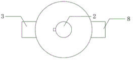
fig. 3 is a top view of the mixing machine of the present invention.
As shown in the figure: 1. a mixer main body; 2. a mixer top cover; 3. a first motor housing; 4. a first rotating shaft; 5. a first cutter head; 6. a second rotating shaft; 7. a second cutter head; 8. a second motor housing; 9. a third rotating shaft; 10. a third cutter head; 11. a fourth rotating shaft; 12. a fourth cutter head; 13. a partition plate; 14. a bottom motor; 15. a fifth rotating shaft; 16. a fifth cutter head; 17. a wire brush; 18. and (4) discharging the pipe.
Detailed Description
The technical solutions in the embodiments of the present invention will be described clearly and completely with reference to the accompanying drawings in the embodiments of the present invention, and it is obvious that the described embodiments are only some embodiments of the present invention, not all embodiments. Based on the embodiments in the present invention, all other embodiments obtained by a person skilled in the art without creative work belong to the protection scope of the present invention.
In the description of the present invention, it is to be noted that, unless otherwise explicitly specified or limited, the terms "mounted", "provided", "sleeved/connected", "connected", and the like are to be understood in a broad sense, such as "connected", which may be fixedly connected, detachably connected, or integrally connected; can be mechanically or electrically connected; they may be connected directly or indirectly through intervening media, or they may be interconnected between two elements. The specific meaning of the above terms in the present invention can be understood in specific cases to those skilled in the art.
Referring to fig. 1 to 3, in the embodiment of the present invention, a mixer with high uniform mixing degree comprises a mixer main body 1, a mixer top cap 2 and a discharge pipe 18, wherein an outer wall of one side of the mixer main body 1 is fixedly connected to an outer wall of one side of a first motor housing 3, a first motor output shaft in the first motor housing 3 is fixedly connected to one end of a first rotating shaft 4, a second motor output shaft in the first motor housing 3 is fixedly connected to one end of a second rotating shaft 6, an outer wall of the first rotating shaft 4 is fixedly connected to an inner wall of a first cutter head 5, an outer wall of the second rotating shaft 6 is fixedly connected to an inner wall of a second cutter head 7, an outer wall of the other side of the mixer main body 1 is fixedly connected to one side of a second motor housing 8, a first motor output shaft in the second motor housing 8 is fixedly connected to one end of a third rotating shaft 9, and a second motor output shaft in the second motor housing 8 is fixedly connected to one end of a fourth rotating shaft 11, the outer wall of the third rotating shaft 9 is fixedly connected with the inner wall of the third cutter head 10, and the outer wall of the fourth rotating shaft 11 is fixedly connected with the inner wall of the fourth cutter head 12.
The outer wall of one side of the mixer main body 1 is fixedly connected with the outer wall of one side of the first motor shell 3, a first motor output shaft in the first motor shell 3 is fixedly connected with one end of a first rotating shaft 4, a second motor output shaft in the first motor shell 3 is fixedly connected with one end of a second rotating shaft 6, the outer wall of the first rotating shaft 4 is fixedly connected with the inner wall of a first cutter head 5, the outer wall of the second rotating shaft 6 is fixedly connected with the inner wall of a second cutter head 7, the outer wall of the other side of the mixer main body 1 is fixedly connected with one side of a second motor shell 8, the first motor output shaft in the second motor shell 8 is fixedly connected with one end of a third rotating shaft 9, the second motor output shaft in the second motor shell 8 is fixedly connected with one end of a fourth rotating shaft 11, the outer wall of the third rotating shaft 9 is fixedly connected with the inner wall of a third cutter head 10, the outer wall of the fourth rotating shaft 11 is fixedly connected with the inner wall of a fourth cutter head 12, and the rotating directions of the first cutter head 5 and the second cutter head 7 are opposite, the rotating directions of the third cutter head 10 and the fourth cutter head 12 are opposite, the cutter heads with different directions can divide and mix materials more finely, and the models of the first motor, the second motor, the third motor and the fourth motor are Y90S-2.
Mix 1 bottom of machine main part and 14 top fixed connection of bottom motor, bottom motor 14 output shaft and the 15 bottom fixed connection of fifth pivot, the 15 outer walls of fifth pivot and 16 one end fixed connection of fifth tool bit, the 16 outer walls of fifth tool bit and steel brush 17 bottom fixed connection, steel brush 17 is the steel wire, when the material through once mixing gets into mixing machine main part 1 bottom inside, the outer steel brush 17 of fifth tool bit 16 can refine the breakage to the material, play certain grinding effect simultaneously, make the material mix more even, the bottom motor model is Y112M-2.
After mixing machine top cap 2 and opening, the material gets into and mixes inside machine main part 1, at first tool bit 5, second tool bit 7, under the effect of third tool bit 10 and fourth tool bit 12, carry out breakage and mix the material, after the breakage is accomplished, through division board 13 with the even transmission of material to mixing machine main part 1 lower floor, under the drive of bottom motor 14, fifth pivot 15 drives fifth tool bit 16 and carries out work, fifth tool bit 16 and wire brush 17 carry out further mixing and grinding to the material, take out the material through discharging pipe 18 at last.
According to the utility model provides an above-mentioned preferred embodiment, when needing to use, open and mix machine top cap 2, pour the material into, take out the material through discharging pipe 18 after mixing in mixing machine main part 1.
Although the present invention has been described in detail with reference to the foregoing embodiments, it will be apparent to those skilled in the art that modifications may be made to the embodiments or portions thereof without departing from the spirit and scope of the invention, and the following claims are therefore to be read in this light of the appended claims.