Suction plate structure of artificial board sander
Technical Field
The utility model relates to a suction disc device, more specifically say, it relates to a suction disc structure of wood-based plate grinder.
Background
The artificial board is a board or a molded product which is made by taking wood or other non-wood plants as raw materials, separating the raw materials into various unit materials through certain mechanical processing and then gluing the unit materials with or without adhesive and other additives. In the processing process of the artificial board, the artificial board needs to be sanded on a sander. In the sanding process, the artificial board is generally conveyed to a sander by using a suction plate structure. The traditional suction plate structure is generally that a cylinder and a vacuum chuck are combined for use, an artificial board is placed on a lifting platform, then the cylinder drives the vacuum chuck to descend to be in contact with the artificial board, and the artificial board is adsorbed and fixed by the vacuum chuck and is sent into a sander. But traditional suction disc structure, vacuum chuck direct and wood-based plate contact, because the wood-based plate surface can mix some dust or impurity such as saw-dust, can have the insecure problem of absorption between vacuum chuck and the wood-based plate, the wood-based plate drops and damages easily appearing at the suction disc in-process, causes the problem of potential safety hazard even.
SUMMERY OF THE UTILITY MODEL
The to-be-solved technical problem of the utility model is not enough to the above-mentioned of prior art, provide a suction disc structure of wood-based plate grinder, can drive the impurity on wood-based plate surface before vacuum chuck adsorbs, improve the absorptive fastness of wood-based plate.
The technical scheme of the utility model is like this: a suction plate structure of an artificial board sander, which comprises a supporting frame and a lifting platform arranged at the lower part of the supporting frame, the upper part of the supporting frame is provided with an electric sliding rail, the bottom of a sliding block of the electric sliding rail is provided with a cylinder, the bottom of the cylinder is provided with a mounting plate, the bottom of the mounting plate is provided with two supports, the bottoms of the two supports are both provided with vacuum chucks, a movable shell is arranged in the vacuum chuck, a plurality of air injection holes are arranged at the bottom of the shell, the top of the shell is connected with a hollow pipe through a sealing bearing, the hollow pipe is fixedly connected with the support, the support at the periphery of the hollow pipe is also provided with an annular air passage, the lower part of the support is also provided with a plurality of air suction passages communicated with the annular air passage and the vacuum chuck, a connecting shaft is fixed at the bottom of the inner wall of the shell, one end of the connecting shaft extends into the hollow pipe, and a fan blade is arranged on the connecting shaft in the hollow pipe; the top of the mounting plate is respectively provided with a vacuum pump and an air blower, the vacuum pump is communicated with the annular air passage, and the air blower is communicated with the hollow pipe.
As a further improvement, an air inlet pipe is arranged on one side of the vacuum pump, a first switch valve is arranged on the air inlet pipe, and the tail end of the air inlet pipe is communicated with the annular air passages corresponding to the two supports through the shunt pipes.
Furthermore, an air outlet pipe is arranged on one side of the air blower, a second switch valve is arranged on the air outlet pipe, an air outlet channel communicated with the tail end of the air outlet pipe is arranged in the mounting plate, and the top end of the hollow pipe penetrates through the support and is communicated with the air outlet channel.
Furthermore, the gas injection holes are inclined holes extending towards the periphery of the shell in an inclined mode.
Furthermore, a rubber ring is fixedly arranged on the bottom surface of the vacuum chuck.
Furthermore, the lifting platform is a scissor type lifting platform.
Advantageous effects
Compared with the prior art, the utility model, have following advantage:
the utility model discloses a suction plate structure, through setting up parts such as casing in vacuum chuck, when the suction plate, electronic slide rail moves vacuum chuck to appointed place, then the cylinder motion moves vacuum chuck to one side near the wood-based plate, in this process, the air-blower blows to the casing through the hollow tube, the fan leaf is driven by gas, the fan leaf drives the casing through the connecting axle and rotates, make the casing rotate, blow to the bottom surface of vacuum chuck through the jet hole on one side, can blow away the impurity near vacuum chuck; after the vacuum chuck contacts the artificial board, the blower stops working, meanwhile, the vacuum pump works, the inner cavity of the vacuum chuck is vacuumized through the annular air passage and the air suction passage, the artificial board can be fixedly adsorbed by the vacuum chuck at the moment, and the suction plate structure can remove impurities on the surface of the artificial board before the artificial board is adsorbed by the vacuum chuck, so that the firmness of the artificial board adsorption is improved, and the problem that the artificial board is damaged due to the fact that the artificial board drops in the conveying process is solved.
Drawings
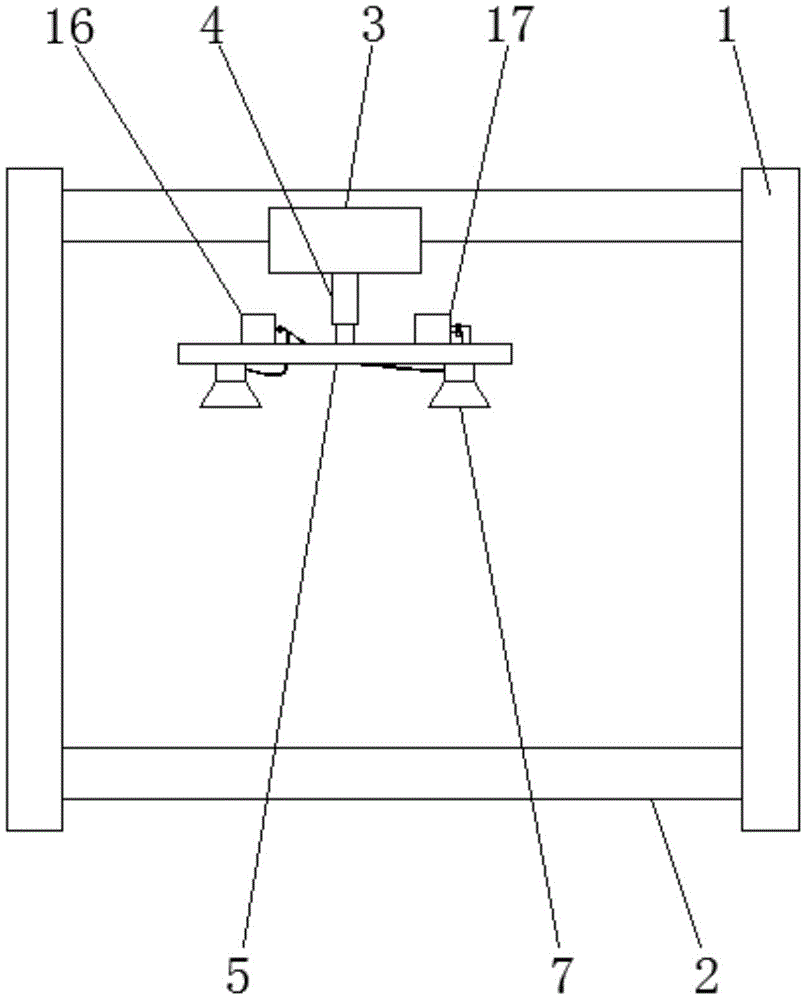
Fig. 1 is a schematic structural view of the present invention;
FIG. 2 is an enlarged schematic view of the cross-sectional structure of the mounting plate of the present invention;
fig. 3 is an enlarged schematic view of the structure at a in fig. 2.
Wherein: 1-support frame, 2-lifting platform, 3-electric slide rail, 4-cylinder, 5-mounting plate, 6-support, 7-vacuum chuck, 8-shell, 9-air jet hole, 10-sealed bearing, 11-hollow tube, 12-annular air flue, 13-air suction channel, 14-connecting shaft, 15-fan blade, 16-vacuum pump, 17-blower, 18-air inlet pipe, 19-first switch valve, 20-shunt pipe, 21-air outlet pipe, 22-second switch valve, 23-air outlet channel and 24-rubber ring.
Detailed Description
The invention will be further described with reference to specific embodiments shown in the drawings.
Referring to fig. 1-3, the suction plate structure of artificial board sander of the present invention comprises a support frame 1 and a lifting platform 2 disposed at the lower part of the support frame 1, an electric slide rail 3 is disposed at the upper part of the support frame 1, an air cylinder 4 is disposed at the bottom of the slide block of the electric slide rail 3, a mounting plate 5 is disposed at the bottom of the air cylinder 4, two supports 6 are disposed at the bottom of the mounting plate 5, vacuum chucks 7 are disposed at the bottoms of the two supports 6, a movable housing 8 is disposed in the vacuum chucks 7, a plurality of air injection holes 9 are disposed at the bottom of the housing 8, a hollow tube 11 is connected to the top of the housing 8 through a sealed bearing 10, the hollow tube 11 is fixedly connected to the supports 6, an annular air passage 12 is further disposed on the supports 6 at the periphery of the hollow tube 11, a plurality of air suction passages 13 communicating the annular air passage 12 with the vacuum chucks 7 are further disposed at the lower part of the supports 6, a hollow tube 14 is fixed at the bottom of the inner wall of the housing 8, one end of the connecting shaft 14 extends into the hollow tube 11, and the connecting shaft 14 in the hollow tube 11 is provided with a fan blade 15; a vacuum pump 16 and a blower 17 are respectively arranged on the top of the mounting plate 5, wherein the vacuum pump 16 is communicated with the annular air passage 12, and the blower 17 is communicated with the hollow pipe 11.
The utility model discloses a suction plate structure, through setting up parts such as casing 8 in vacuum chuck 7, when the suction plate, electronic slide rail 3 removes vacuum chuck 7 to appointed place, then cylinder 4 moves vacuum chuck 7 to one side near the wood-based plate, in this process, air-blower 17 blows to casing 8 in through hollow tube 11, fan leaf 15 is driven by gas, fan leaf 15 drives casing 8 through connecting axle 14 and rotates, make casing 8 rotate, blow to the bottom surface of vacuum chuck 7 through fumarole 9 on one side, can blow away the impurity near vacuum chuck 7; after the vacuum chuck 7 contacts the artificial board, the blower 17 stops working, meanwhile, the vacuum pump 16 works, the inner cavity of the vacuum chuck 7 is vacuumized through the annular air passage 12 and the air suction passage 13, the artificial board can be fixedly adsorbed by the vacuum chuck 7 at the moment, impurities on the surface of the artificial board can be removed by the suction plate structure before the vacuum chuck adsorbs, the firmness of artificial board adsorption is improved, and the artificial board is prevented from falling and being damaged in the conveying process.
Preferably, an air inlet pipe 18 is arranged on one side of the vacuum pump 16, a first switch valve 19 is arranged on the air inlet pipe 18 and used for controlling the opening and closing of the pipeline, and the tail end of the air inlet pipe 18 is communicated with the annular air passages 12 corresponding to the two supports 6 through a shunt pipe 20. The vacuum pump 16 is used for vacuumizing the two shunt tubes 20 through the air inlet pipe 18, so that the annular air passage 12 generates negative pressure, the annular air passage 12 generates negative pressure in the vacuum sucker 7 through the air suction passage 13, the artificial board is adsorbed and fixed, the air inlet pipe 18, the first switch valve 19, the circulator 12 and the air suction passage 13 are matched for use, the structural layout is reasonably optimized, and the pipeline is easy to control to be opened and closed.
Preferably, an air outlet pipe 21 is arranged on one side of the blower 17, a second switch valve 22 is arranged on the air outlet pipe 21, an air outlet channel 23 communicated with the tail end of the air outlet pipe 21 is arranged in the mounting plate 5, and the top end of the hollow pipe 11 penetrates through the support 6 and is communicated with the air outlet channel 23. Air-blower 17 supplies air to gas outlet channel 23 through outlet duct 21, and gas outlet channel 23 redistributes to hollow tube 11 for gas can blow fan blade 15 and rotate, and its outlet duct 21, second ooff valve 22, gas outlet channel 23 and hollow tube 11's cooperation is used, has rationally optimized structural layout, and easily controls opening and close of pipeline.
Preferably, the gas injection hole 9 is an inclined hole extending obliquely towards the periphery of the housing 8, so that gas is obliquely blown towards the periphery of the vacuum chuck 7, and impurities below the vacuum chuck 7 are guaranteed to be blown away.
Preferably, the bottom surface of the vacuum chuck 7 is further fixedly provided with a rubber ring 24, so that the sealing performance of the vacuum chuck 7 is improved, and the adsorption firmness is better.
Preferably, the lifting platform 2 is a scissor type lifting platform, and the bearing capacity is better.
The above is only the preferred embodiment of the present invention, and it should be noted that for those skilled in the art, without departing from the structure of the present invention, several modifications and improvements can be made, which will not affect the utility model and the utility of the patent.