CN215029435U - Colloid powder feeding and grinding integrated device - Google Patents
Colloid powder feeding and grinding integrated device Download PDFInfo
- Publication number
- CN215029435U CN215029435U CN202022939922.2U CN202022939922U CN215029435U CN 215029435 U CN215029435 U CN 215029435U CN 202022939922 U CN202022939922 U CN 202022939922U CN 215029435 U CN215029435 U CN 215029435U
- Authority
- CN
- China
- Prior art keywords
- grinding
- vacuum pump
- grinding plate
- feeding
- feeding pipe
- Prior art date
- Legal status (The legal status is an assumption and is not a legal conclusion. Google has not performed a legal analysis and makes no representation as to the accuracy of the status listed.)
- Active
Links
Images

Landscapes
- Crushing And Grinding (AREA)
Abstract
A colloid powder feeding and grinding integrated device comprises a feeding pipe, a vacuum pump and a grinding device; a hopper is arranged at a feed port of the feeding pipe, and an opening of the feed port of the hopper is upward; a discharge hole of the feeding pipe is provided with a bell-mouth-shaped pressure relief cabin, and the smaller end of the pressure relief cabin is connected with the discharge hole of the feeding pipe; the vacuum pump is connected in series to the feeding pipe; the rotation axis of an impeller of the vacuum pump is vertical to the ground, and the axis of a discharge hole of a volute of the vacuum pump is parallel to the ground; the axes of a feed inlet of the vacuum pump and the impeller are superposed; the opening of the feed inlet of the vacuum pump faces downwards. The device integrates feeding and grinding, and is suitable for grinding and feeding fine powder.
Description
Technical Field
The utility model belongs to the technical field of the colloid production, specifically a send and grind integrative device of colloid powder.
Background
In the prior art, raw materials such as sealant, masonry glue and the like contain quartz micro powder, silicon micro powder and/or carbon black micro powder and the like. These powders are mixed with resins or other colloids to give products. Here, it is necessary that these fine powder particles are sufficiently uniform and small to ensure a high quality of the product. The fineness of the micro powder is detected by a special instrument and a specific method (a laser diffraction scattering method, a centrifugal sedimentation method and the like) generally in a laboratory environment. The powder raw materials are purchased in factories, and the fineness of the powder is determined through detection reports provided by suppliers. Due to the restriction of various objective factors such as storage and transportation, the fineness of the powder material is more or less uneven or caked, which affects the quality of the final product and increases the production cost (for example, the stirring time needs to be increased).
Disclosure of Invention
In order to solve the above problems existing in the prior art, the utility model provides a colloid powder send and grind integrative device. The background of the development of the device is that in the current production practice, powder is directly put into a mixing machine such as a kneader and the like through a hopper. The powder material of most products, because of its very small size, is in a fluid form (like toner for laser printers). If the powder can be directly fed into a mixing machine through a sealed pipeline in a closed space, the powder can be directly fed into the mixing machine through the sealed pipeline, and the dust pollution of a production site can be reduced. And the grinding device is added in the feeding pipeline, so that the caking problem can be solved to a certain extent, and the powder can be ground for the second time. Based on the above thought, the utility model discloses a technical scheme as follows:
a colloid powder feeding and grinding integrated device comprises a feeding pipe, a vacuum pump and a grinding device;
a hopper is arranged at a feed port of the feeding pipe, and an opening of the feed port of the hopper is upward; a discharge hole of the feeding pipe is provided with a bell-mouth-shaped pressure relief cabin, and the smaller end of the pressure relief cabin is connected with the discharge hole of the feeding pipe;
the vacuum pump is connected in series to the feeding pipe; the rotation axis of an impeller of the vacuum pump is vertical to the ground, and the axis of a discharge hole of a volute of the vacuum pump is parallel to the ground; the axes of a feed inlet of the vacuum pump and the impeller are superposed; the opening of the feed port of the vacuum pump faces downwards;
the grinding device comprises a shell, a first grinding plate and a second grinding plate; the shell is cylindrical; the first grinding plate is in a shape of a round cake, and the second grinding plate is in a shape of a circular ring; the diameter of the first grinding plate is smaller than that of the second grinding plate; the second grinding plate is fixedly connected in the shell, the axis of the second grinding plate is superposed with the axis of the shell, and the outer circumference of the second grinding plate is closely attached to the inner wall of the shell; the circle center position of the first grinding plate is connected with a driving shaft, and a bearing seat connected with a bearing of the driving shaft is fixed in the shell through a connecting mechanism (such as a connecting rod); the axis of the first grinding plate is superposed with the axis of the shell;
the bottom surface of the first grinding plate is connected with a plurality of arc-shaped convex edges, the arc-shaped convex edges are in central symmetry around the circle center of the first grinding plate, one end of each arc-shaped convex edge points to the circle center of the first grinding plate, and the other end of each arc-shaped convex edge points to the outer edge of the first grinding plate; the bottom surface of the arc-shaped convex edge of the first grinding plate is matched with the top surface of the second grinding plate to form a grinding surface;
the driving shaft is detachably connected with a rotating shaft of an impeller of the vacuum pump, and the shell is detachably connected to the feeding pipe; the vacuum pump and the grinding device form a group of feeding and grinding units.
When specifically realizing, grinder's casing can adopt flange joint mode to connect on the conveying pipe.
The utility model has the principle that the impeller vacuum pump can be adopted to convey powder with high density, fine particles and fluid shape to replace the traditional auger. From a cost perspective, the impeller vacuum pump is lower than the auger. Since the powder itself is fine and the hardness of the agglomerates is low even if they agglomerate, the power requirement of the grinding apparatus is not high, for which the grinding function can be safely realized with a small power of the part from which the vacuum pump can be divided. A more powerful motor may also be used as appropriate.
The convex edge on the bottom surface of the first grinding plate rotates at high speed with the first grinding plate, and then pressure difference similar to the pressure difference between the center and the periphery of the impeller is generated, so that powder enters from the middle of the first grinding plate (the hollow part of the second grinding plate) and exits from the outer edge of the first grinding plate and is sucked by the vacuum pump.
The opening of the feed inlet of the hopper faces upwards, the opening of the feed inlet of the vacuum pump faces downwards, and a closed space is formed between the feed inlet of the hopper and the feed inlet of the vacuum pump after the feed inlet of the vacuum pump is filled with materials, so that the feeding efficiency is improved.
Because the discharge of the vacuum pump in the closed pipeline is in a jet shape, if the powder is directly sent to the mixing machine, the powder can be raised, and the like, therefore, the discharge hole of the feeding pipe is connected with the pressure relief cabin, so that the powder can freely fall in the pressure relief cabin and can slide into the feeding of the mixing machine.
Further, the feeding grinding unit is provided with a plurality of feeding grinding units which are connected on the feeding pipe in series.
The multiple feed grinding units provide greater operating capability for specific requirements.
Further, still include 1 or a plurality of independent vacuum pump, independent vacuum pump is connected in series on the conveying pipe.
In order to improve the feeding capacity, an independent vacuum pump can be added to play a feeding role only.
Furthermore, the top surface of second grinding plate is equipped with a plurality of annular beads, and each annular bead diameter reduces in proper order, and the centre of a circle the same with second grinding plate. Under this structure, the grinding effect has been optimized.
Further, in a group of feed grinding units: a corresponding key connection structure is arranged between the front part of the rotating shaft of the vacuum pump and the impeller; the front part of a rotating shaft of the vacuum pump is provided with an external thread, and a nut is screwed on the external thread;
an inner hexagonal groove is formed in the nut, a hexagonal prism is arranged at the top end of the driving shaft, and the hexagonal prism is detachably inserted into the inner hexagonal groove.
Further, the inner diameter of the second grinding plate is not less than the inner diameter of a feed port of the vacuum pump; the inner cavity of the shell at the position of the first grinding plate and the second grinding plate is in a bulge shape. The scheme is used for ensuring the flow rate of the vacuum pump.
Adopt this structure, easy dismounting, if the condition such as grinder card hinders has appeared moreover, the nut and hexagonal prism these parts of being convenient for maintain and change of at first damaging. The connection structure of the inner hexagonal groove/the hexagonal column has higher fault tolerance on the length of the driving shaft. The direction of the external thread, the rotation direction of the impeller and the rotation direction of the first grinding plate (convex edge) are matched, so that when all parts rotate along with the motor of the vacuum pump, the screw cap and the external thread attract each other, the impeller sucks materials, and the first grinding plate discharges materials to the periphery.
The feeding device integrates feeding and grinding and is suitable for grinding and feeding fine powder.
Drawings
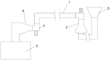
FIG. 1 is a schematic view of the overall structure of the device of the present invention;
fig. 2 is a schematic structural view of the feeding and grinding unit of the present invention;
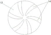
FIG. 3 is a schematic bottom view of a first lapping plate;
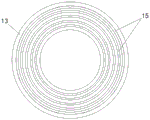
FIG. 4 is a schematic top view of a second lapping plate;
in the figure: the device comprises a feeding pipe 1, a feeding grinding unit 2, a mixing machine 3, an independent vacuum pump 4, a hopper 5, a pressure relief cabin 6, an impeller 7 of the vacuum pump, a volute 8 of the vacuum pump, a discharge hole 9 of the volute of the vacuum pump, a feed inlet 10 of the vacuum pump, a shell 11, a first grinding plate 12, a second grinding plate 13, an arc-shaped rib 14, an annular rib 15, a driving shaft 16, a bearing 17 of the driving shaft and a screw cap 18.
Detailed Description
The present invention is described below with reference to the accompanying drawings:
referring to fig. 1, an integrated grinding and feeding device for powder for colloid comprises a feeding pipe, a vacuum pump and a grinding device; a hopper is arranged at a feed port of the feeding pipe, and an opening of the feed port of the hopper is upward; a discharge hole of the feeding pipe is provided with a bell-mouth-shaped pressure relief cabin, and the smaller end of the pressure relief cabin is connected with the discharge hole of the feeding pipe; the vacuum pump is connected in series to the feeding pipe; the rotation axis of an impeller of the vacuum pump is vertical to the ground, and the axis of a discharge hole of a volute of the vacuum pump is parallel to the ground; the axes of a feed inlet of the vacuum pump and the impeller are superposed;
as shown in fig. 2, the grinding apparatus includes a housing, a first grinding plate, and a second grinding plate; the shell is cylindrical; the first grinding plate is in a shape of a round cake, and the second grinding plate is in a shape of a circular ring; the diameter of the first grinding plate is smaller than that of the second grinding plate; the second grinding plate is fixedly connected in the shell, and the axis of the second grinding plate is superposed with the axis of the shell; the circle center position of the first grinding plate is connected with a driving shaft, and a bearing seat connected with a bearing of the driving shaft is fixed in the shell through a connecting mechanism; the axis of the first grinding plate is superposed with the axis of the shell;
as shown in fig. 3 and 4, the bottom surface of the first grinding plate is connected with a plurality of arc-shaped ribs, each arc-shaped rib is centrosymmetric around the center of the circle of the first grinding plate, one end of each arc-shaped rib points to the center of the circle of the first grinding plate, and the other end points to the outer edge of the first grinding plate; the bottom surface of the arc-shaped convex edge of the first grinding plate is matched with the top surface of the second grinding plate to form a grinding surface;
the driving shaft is detachably connected with a rotating shaft of an impeller of the vacuum pump, and the shell is detachably connected to the feeding pipe; the vacuum pump and the grinding device form a group of feeding and grinding units.
The inner diameter of the second grinding plate is not less than the inner diameter of a feed port of the vacuum pump; the inner cavity of the shell at the position of the first grinding plate and the second grinding plate is in a bulge shape.
The top surface of second grinding plate is equipped with a plurality of annular beads, and each annular bead diameter reduces in proper order, and the centre of a circle the same with second grinding plate.
In a set of feed grinding units: a corresponding key connection structure is arranged between the front part of the rotating shaft of the vacuum pump and the impeller; the front part of a rotating shaft of the vacuum pump is provided with an external thread, and a nut is screwed on the external thread;
an inner hexagonal groove is formed in the nut, a hexagonal prism is arranged at the top end of the driving shaft, and the hexagonal prism is detachably inserted into the inner hexagonal groove.
According to the engineering requirement, the feeding grinding unit is provided with a plurality of feeding grinding units which are connected on the feeding pipe in series. Still include 1 or a plurality of independent vacuum pump, independent vacuum pump series connection is on the conveying pipe.
Claims (6)
1. A colloid powder feeding and grinding integrated device is characterized by comprising a feeding pipe, a vacuum pump and a grinding device;
a hopper is arranged at a feed port of the feeding pipe, and an opening of the feed port of the hopper is upward; a discharge hole of the feeding pipe is provided with a bell-mouth-shaped pressure relief cabin, and the smaller end of the pressure relief cabin is connected with the discharge hole of the feeding pipe;
the vacuum pump is connected in series to the feeding pipe; the rotation axis of an impeller of the vacuum pump is vertical to the ground, and the axis of a discharge hole of a volute of the vacuum pump is parallel to the ground; the axes of a feed inlet of the vacuum pump and the impeller are superposed;
the grinding device comprises a shell, a first grinding plate and a second grinding plate; the shell is cylindrical; the first grinding plate is in a shape of a round cake, and the second grinding plate is in a shape of a circular ring; the diameter of the first grinding plate is smaller than that of the second grinding plate; the second grinding plate is fixedly connected in the shell, and the axis of the second grinding plate is superposed with the axis of the shell; the circle center position of the first grinding plate is connected with a driving shaft, and a bearing seat connected with a bearing of the driving shaft is fixed in the shell through a connecting mechanism; the axis of the first grinding plate is superposed with the axis of the shell;
the bottom surface of the first grinding plate is connected with a plurality of arc-shaped convex edges, the arc-shaped convex edges are in central symmetry around the circle center of the first grinding plate, one end of each arc-shaped convex edge points to the circle center of the first grinding plate, and the other end of each arc-shaped convex edge points to the outer edge of the first grinding plate; the bottom surface of the arc-shaped convex edge of the first grinding plate is matched with the top surface of the second grinding plate to form a grinding surface;
the driving shaft is detachably connected with a rotating shaft of an impeller of the vacuum pump, and the shell is detachably connected to the feeding pipe; the vacuum pump and the grinding device form a group of feeding and grinding units.
2. A colloidal powder feeding and grinding integrated device as defined in claim 1, wherein said feeding and grinding unit is provided in plurality and is connected in series to a feeding pipe.
3. A colloidal powder feeding and grinding integrated device as defined in claim 1, further comprising 1 or more independent vacuum pumps connected in series to the feeding pipe.
4. A colloidal powder feeding and grinding integrated device as defined in claim 1 or 2, wherein the top surface of the second grinding plate is provided with a plurality of annular ribs, and the diameters of the annular ribs are sequentially reduced and are the same as the center of the circle of the second grinding plate.
5. A colloidal powder feeding and grinding integrated device according to claim 1 or 2, characterized in that in a group of feeding and grinding units: a corresponding key connection structure is arranged between the front part of the rotating shaft of the vacuum pump and the impeller; the front part of a rotating shaft of the vacuum pump is provided with an external thread, and a nut is screwed on the external thread;
an inner hexagonal groove is formed in the nut, a hexagonal prism is arranged at the top end of the driving shaft, and the hexagonal prism is detachably inserted into the inner hexagonal groove.
6. A colloidal powder feeding and grinding integrated device as defined in claim 1, wherein the second grinding plate has an inner diameter not smaller than that of the feed port of the vacuum pump.
Priority Applications (1)
| Application Number | Priority Date | Filing Date | Title |
|---|---|---|---|
| CN202022939922.2U CN215029435U (en) | 2020-12-11 | 2020-12-11 | Colloid powder feeding and grinding integrated device |
Applications Claiming Priority (1)
| Application Number | Priority Date | Filing Date | Title |
|---|---|---|---|
| CN202022939922.2U CN215029435U (en) | 2020-12-11 | 2020-12-11 | Colloid powder feeding and grinding integrated device |
Publications (1)
| Publication Number | Publication Date |
|---|---|
| CN215029435U true CN215029435U (en) | 2021-12-07 |
Family
ID=79214679
Family Applications (1)
| Application Number | Title | Priority Date | Filing Date |
|---|---|---|---|
| CN202022939922.2U Active CN215029435U (en) | 2020-12-11 | 2020-12-11 | Colloid powder feeding and grinding integrated device |
Country Status (1)
| Country | Link |
|---|---|
| CN (1) | CN215029435U (en) |
Cited By (1)
| Publication number | Priority date | Publication date | Assignee | Title |
|---|---|---|---|---|
| CN118179669A (en) * | 2024-03-21 | 2024-06-14 | 山东大学 | A dynamic mixer based on stone mill principle and working method |
-
2020
- 2020-12-11 CN CN202022939922.2U patent/CN215029435U/en active Active
Cited By (1)
| Publication number | Priority date | Publication date | Assignee | Title |
|---|---|---|---|---|
| CN118179669A (en) * | 2024-03-21 | 2024-06-14 | 山东大学 | A dynamic mixer based on stone mill principle and working method |
Similar Documents
| Publication | Publication Date | Title |
|---|---|---|
| CN211385344U (en) | Powder grinding device of vertical paint pulverizer | |
| KR101658410B1 (en) | Dispersing and emulsifying apparatus for high viscosity fluid | |
| WO2017049964A1 (en) | Screen-free intelligent nano-grinding system | |
| CN111921636A (en) | A kind of dispersing grinding drum device for sand mill | |
| CN201969595U (en) | Vertical sand mill | |
| KR20150053068A (en) | Wet grinding and dispersing apparatus for processing of minute particle of materials | |
| CN2491110Y (en) | Wetting continuous feeding/discharging planetary ball mill | |
| CN209791628U (en) | A graphite pulverizer | |
| JP2006212489A (en) | Grinding method using medium stirring type grinder | |
| CN203874845U (en) | Vertical type sand mill | |
| CN205673010U (en) | A kind of horizontal sand mill | |
| JP7429039B2 (en) | wet bead mill | |
| CN212120172U (en) | Water based paint processing grinder | |
| KR101691151B1 (en) | Wet type grinding and dispersing apparatus having preventer of beads flowing | |
| CN219210104U (en) | Raw material crusher for building coating production | |
| CN206082695U (en) | Large -traffic experiment molding sand mill | |
| CN203508117U (en) | Grinding disk for wet ultrafine grinding machine and wet ultrafine grinding machine | |
| CN214636921U (en) | Vertical stirring ball mill of tungsten carbide | |
| CN222969927U (en) | Powder coating reducing mechanism | |
| JP2012179535A (en) | Wet medium agitation mill | |
| CN211070293U (en) | Vertical grinder | |
| CN209302633U (en) | One plant feed bin mixing arrangement | |
| CN208526811U (en) | A kind of mining ore grinding device | |
| CN110694750A (en) | Spiral discharging horizontal sand mill and spiral discharging method | |
| CN220919442U (en) | Horizontal grinding equipment for color mixing color paste |
Legal Events
| Date | Code | Title | Description |
|---|---|---|---|
| GR01 | Patent grant | ||
| GR01 | Patent grant |