CN215022708U - Tuberculosis ward saliva processing apparatus - Google Patents
Tuberculosis ward saliva processing apparatus Download PDFInfo
- Publication number
- CN215022708U CN215022708U CN202120498340.7U CN202120498340U CN215022708U CN 215022708 U CN215022708 U CN 215022708U CN 202120498340 U CN202120498340 U CN 202120498340U CN 215022708 U CN215022708 U CN 215022708U
- Authority
- CN
- China
- Prior art keywords
- fixedly connected
- electric
- processing apparatus
- saliva
- tuberculosis
- Prior art date
- Legal status (The legal status is an assumption and is not a legal conclusion. Google has not performed a legal analysis and makes no representation as to the accuracy of the status listed.)
- Expired - Fee Related
Links
- 210000003296 saliva Anatomy 0.000 title claims abstract description 51
- 201000008827 tuberculosis Diseases 0.000 title claims abstract description 25
- XLYOFNOQVPJJNP-UHFFFAOYSA-N water Substances O XLYOFNOQVPJJNP-UHFFFAOYSA-N 0.000 claims abstract description 25
- 238000001035 drying Methods 0.000 claims abstract description 13
- 239000000645 desinfectant Substances 0.000 claims description 27
- 238000009792 diffusion process Methods 0.000 claims description 23
- 238000007789 sealing Methods 0.000 claims description 19
- 238000004140 cleaning Methods 0.000 claims description 18
- 239000007788 liquid Substances 0.000 claims description 14
- 239000002699 waste material Substances 0.000 claims description 13
- 238000005096 rolling process Methods 0.000 claims description 2
- 230000000694 effects Effects 0.000 abstract description 12
- 238000005406 washing Methods 0.000 abstract description 4
- 238000004659 sterilization and disinfection Methods 0.000 abstract description 2
- 238000001125 extrusion Methods 0.000 abstract 1
- 238000000926 separation method Methods 0.000 abstract 1
- 230000000249 desinfective effect Effects 0.000 description 3
- 208000015181 infectious disease Diseases 0.000 description 2
- 244000052769 pathogen Species 0.000 description 2
- 241000193830 Bacillus <bacterium> Species 0.000 description 1
- 208000035473 Communicable disease Diseases 0.000 description 1
- 206010036790 Productive cough Diseases 0.000 description 1
- 230000004075 alteration Effects 0.000 description 1
- 230000009286 beneficial effect Effects 0.000 description 1
- 230000001684 chronic effect Effects 0.000 description 1
- 238000011010 flushing procedure Methods 0.000 description 1
- 210000004072 lung Anatomy 0.000 description 1
- 238000012986 modification Methods 0.000 description 1
- 230000004048 modification Effects 0.000 description 1
- 210000000056 organ Anatomy 0.000 description 1
- 208000008128 pulmonary tuberculosis Diseases 0.000 description 1
- 210000003802 sputum Anatomy 0.000 description 1
- 208000024794 sputum Diseases 0.000 description 1
- 238000006467 substitution reaction Methods 0.000 description 1
Images

Landscapes
- Dental Tools And Instruments Or Auxiliary Dental Instruments (AREA)
Abstract
The utility model discloses a tuberculosis ward saliva processing apparatus relates to saliva processing apparatus technical field, comprising a base plate, the equal fixedly connected with rubber base in bottom both sides of bottom plate, the top one side fixedly connected with of bottom plate bears the case, the top opposite side fixedly connected with of bottom plate washs the case, wash the top fixedly connected with water tank of case. This tuberculosis ward saliva processing apparatus, through the positioning track, a drive uni, drying device, electric chuck and electric valve's cooperation setting, saliva when the patient advances new abundant disinfection back, start electric telescopic handle, electric telescopic handle extrusion electric chuck makes the surface contact of electric chuck and inner bag, start electric chuck, electric chuck stabilizes the inner bag and adsorbs, start the hydraulic stem, the hydraulic stem makes cassette and inner bag separation, reach and carry out abluent effect to the inner bag, the convenience of device has been improved, guarantee to carry out abundant washing to the inner bag, the reuse of being convenient for.
Description
Technical Field
The utility model relates to a saliva processing apparatus technical field specifically is a tuberculosis ward saliva processing apparatus.
Background
Tuberculosis is a chronic infectious disease caused by infection of tubercle bacillus, which may invade various organs of the whole body of a human body, but mainly invades lungs, which is called as pulmonary tuberculosis, saliva of tuberculosis patients is infected, so that special collection and treatment of the saliva are needed, and the saliva treatment device can properly treat the saliva. The existing tuberculosis ward saliva treatment device has a poor saliva treatment effect.
The problem that the inner container is inconvenient to clean when the existing tuberculosis ward saliva treatment device is poor in saliva treatment effect is solved.
Therefore, it is necessary to provide a sputum processing device for tuberculosis unit to solve the above problems.
SUMMERY OF THE UTILITY MODEL
Technical problem to be solved
An object of the utility model is to provide a tuberculosis ward saliva processing apparatus to be not convenient for carry out abluent problem to the inner bag when relatively poor to saliva treatment effect among the current tuberculosis ward saliva processing apparatus who provides among the solution above-mentioned background art.
(II) technical scheme
In order to achieve the above purpose, the utility model discloses a following technical scheme realizes: a tuberculosis ward saliva treatment device comprises a bottom plate, wherein both sides of the bottom end of the bottom plate are fixedly connected with rubber bases, one side of the top end of the bottom plate is fixedly connected with a bearing box, the other side of the top end of the bottom plate is fixedly connected with a cleaning box, the top end of the cleaning box is fixedly connected with a water tank, the middle part of the bottom end of the water tank is fixedly connected with a connecting seat, the middle part of the bottom end of the connecting seat is fixedly connected with a high-pressure nozzle, both sides of the bottom end of the connecting seat are fixedly connected with an electric power supply device, the bottom end of the electric power supply device is fixedly connected with a drying device, the middle part of the bottom end inside the cleaning box is fixedly connected with a bearing platform, the middle part of the top end of the bottom plate is fixedly connected with a waste liquid collecting box, the middle part of the top end of the bearing box is fixedly connected with a conveying pipeline, the bottom end of the conveying pipeline is fixedly connected with a sealing cover, and the top end of the conveying pipeline is fixedly connected with an inlet end, the two sides of the inlet end are fixedly connected with diffusion nozzles, the two sides of the top end of the bearing box are fixedly connected with a disinfectant box, the top end of the disinfectant box is fixedly connected with a hydraulic pump, the top end of the hydraulic pump is fixedly connected with a conveying pipeline, one end of the conveying pipeline, which is far away from the hydraulic pump, is fixedly connected with the diffusion nozzles, the two sides of the inner part of the bearing box are fixedly connected with positioning rails, the inner side of each positioning rail is movably connected with a driving device, the two ends of one side, which is far away from the positioning rails, of the driving device are fixedly connected with an electric telescopic rod, one end of a piston rod of the electric telescopic rod is fixedly connected with an electric suction cup, the middle part of the bottom end of the inner side of the bearing box is fixedly connected with a hydraulic rod, the top end of the hydraulic rod is fixedly connected with a servo motor, the top end of the servo motor is limited and connected with a clamping seat, and the inner side of the clamping seat is movably connected with an inner container, an electric valve is arranged in the middle of the bottom end of the inner side of the inner container, and a rotating disc is arranged on the outer side of the electric valve.
Preferably, the number of the rubber bases is four, the four rubber bases are symmetrically distributed at the bottom end of the bottom plate, and the four rubber bases are perpendicular to the bottom plate.
Preferably, there are two positioning rails, and the two positioning rails are symmetrically distributed inside the carrying box and the cleaning box.
Preferably, the number of the electric telescopic rods is four, the electric telescopic rods are symmetrically distributed on one side of the driving device, and the electric telescopic rods are perpendicular to the electric suction cups.
Preferably, the electric suction cups are two, the electric suction cups are symmetrically distributed on one side of the electric telescopic rod, and the arc length diameter of the electric suction cups is equal to the diameter of the inner container.
Preferably, the central line of the clamping seat is parallel to the central line of the inner container, and the inner diameter of the clamping seat is equal to the outer diameter of the inner container.
Preferably, the central line of the conveying pipeline and the central line of the sealing cover are the same straight line, and the conveying pipeline is perpendicular to the sealing cover.
Preferably, there are two diffusion nozzles, the two diffusion nozzles are symmetrically distributed on two sides of the inlet end, and the central lines of the two diffusion nozzles are the same straight line.
(III) advantageous effects
Compared with the prior art, the utility model provides a tuberculosis ward saliva processing apparatus possesses following beneficial effect:
1. the tuberculosis ward saliva processing device comprises a conveying pipeline, a diffusion nozzle, a servo motor, a sealing cover and a disinfectant box, wherein when a patient needs to spit, a hydraulic pump is started firstly, disinfectant in the disinfectant box is transferred to the inside of the diffusion nozzle through a conveying pipeline by the hydraulic pump, the side wall of an inlet end and the side wall of the conveying pipeline form disinfectant water flow by the diffusion nozzle, the patient spits saliva from the inlet end to the disinfectant water flow and goes into an inner container along with the disinfectant water flow, a hydraulic rod is started, the hydraulic rod enables a clamping seat to ascend, the clamping seat drives the inner container to ascend, the inner container extrudes the sealing cover, the sealing cover enables the inner container to form a closed ring, the servo motor is started, the inner container is driven to rotate by the clamping seat, a rotating disc in the inner container uniformly mixes the saliva of the patient and the flowed disinfectant and disinfects in the saliva of the patient, reach the effect of disinfecting patient's saliva, improved the practicality of device, guarantee to fully disinfect the saliva that the patient produced.
2. The tuberculosis ward saliva treatment device comprises a positioning track, a driving device, a drying device, an electric sucker and an electric valve, wherein when saliva of a patient is sufficiently disinfected, the electric telescopic rod is started, the electric telescopic rod extrudes the electric sucker and enables the electric sucker to be in contact with the surface of an inner container, the electric sucker is started, the inner container is stably adsorbed by the electric sucker, a hydraulic rod is started, a clamping seat is separated from the inner container by the hydraulic rod, the driving device is started, the inner container is moved to the position right above a waste liquid collecting box by the driving device under the limitation of the positioning track, the electric valve is started, waste liquid in the inner container is transferred to the waste liquid collecting box by the electric valve, the driving device is reused, the inner container is moved to the top end of a bearing platform by the driving device, a high-pressure nozzle is started, water in the inner container is injected into the inner container by the high-pressure nozzle and washes the side surface of the inner container, after the washing is finished, the electric power supply device is started, the electric power supply device supplies electric power for the drying device, the drying device evaporates the water in the inner container, the effect of cleaning the inner container is achieved, the convenience of the device is improved, the inner container is guaranteed to be sufficiently cleaned, and the inner container is convenient to recycle.
Drawings
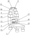
FIG. 1 is an axial view of the structure of the present invention;
FIG. 2 is an axial view of the bearing box structure of the present invention;
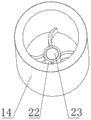
FIG. 3 is a shaft measuring and indicating view of the liner structure of the present invention;
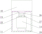
fig. 4 is a schematic sectional view of the structure of the cleaning tank of the present invention.
In the figure: 1. a base plate; 2. a rubber base; 3. a carrying case; 4. a hydraulic pump; 5. a delivery conduit; 6. positioning the track; 7. a drive device; 8. an electric telescopic rod; 9. an electric suction cup; 10. a water tank; 11. a cleaning tank; 12. a waste liquid collection box; 13. a sealing cover; 14. an inner container; 15. a hydraulic lever; 16. a servo motor; 17. a card holder; 18. an inlet end; 19. a disinfectant tank; 20. a delivery conduit; 21. a diffusion nozzle; 22. rotating the disc; 23. an electrically operated valve; 24. a connecting seat; 25. a high pressure nozzle; 26. a power supply device; 27. a drying device; 28. a bearing platform.
Detailed Description
The technical solutions in the embodiments of the present invention will be described clearly and completely with reference to the accompanying drawings in the embodiments of the present invention, and it is obvious that the described embodiments are only some embodiments of the present invention, not all embodiments.
Referring to fig. 1-4, a tuberculosis ward saliva processing device comprises a bottom plate 1, wherein two sides of the bottom end of the bottom plate 1 are fixedly connected with rubber bases 2, four rubber bases 2 are symmetrically distributed at the bottom end of the bottom plate 1, four rubber bases 2 are perpendicular to the bottom plate 1, so as to ensure stable support of the device, so that the device can perform stable work, one side of the top end of the bottom plate 1 is fixedly connected with a bearing box 3, the other side of the top end of the bottom plate 1 is fixedly connected with a cleaning box 11, the top end of the cleaning box 11 is fixedly connected with a water tank 10, the middle part of the bottom end of the water tank 10 is fixedly connected with a connecting seat 24, the middle part of the bottom end of the connecting seat 24 is fixedly connected with a high-pressure nozzle 25, two sides of the bottom end of the connecting seat 24 are fixedly connected with an electric power supply device 26, the bottom end of the electric power supply device 26 is fixedly connected with a drying device 27, and the middle part of the bottom end of the inner side of the cleaning box 11 is fixedly connected with a bearing platform 28, the middle part of the top end of the bottom plate 1 is fixedly connected with a waste liquid collecting box 12, the middle part of the top end of the bearing box 3 is fixedly connected with a conveying pipeline 5, when a patient needs to spit, the conveying pipeline 5, a diffusion nozzle 21, a servo motor 16, a sealing cover 13 and a disinfectant box 19 are arranged in a matched mode, firstly, a hydraulic pump 4 is started, disinfectant in the disinfectant box 19 is transferred to the interior of the diffusion nozzle 21 through a conveying pipeline 20 by the hydraulic pump 4, disinfectant water flow is formed by the diffusion nozzle 21 through an inlet end 18 and the side wall of the conveying pipeline 5, the patient spittle saliva from the inlet end 18 onto the disinfectant water flow and goes into an inner container 14 along with the disinfectant water flow, a hydraulic rod 15 is started, the clamping seat 17 is lifted by the hydraulic rod 15, the clamping seat 17 drives the inner container 14 to lift, the sealing cover 13 is extruded by the inner container 14, the sealing cover 13 forms a closed ring shape of the inner container 14, the servo motor 16 is started, the servo motor 16 drives the inner container 14 to rotate by the clamping seat 17, the rotating disc 22 in the inner container 14 mixes the saliva of the patient and the flowing disinfectant uniformly and disinfects the pathogens in the saliva of the patient, thereby achieving the effect of disinfecting the saliva of the patient, improving the practicability of the device, ensuring that the saliva produced by the patient is disinfected fully, the central line of the conveying pipeline 5 is the same straight line with the central line of the sealing cover 13, the conveying pipeline 5 is vertical to the sealing cover 13, providing stable positioning for the sealing cover 13 and the inlet end 18, and is also a flowing pipeline of the disinfectant, the bottom end of the conveying pipeline 5 is fixedly connected with the sealing cover 13, the top end of the conveying pipeline 5 is fixedly connected with the inlet end 18, both sides of the inlet end 18 are fixedly connected with the diffusion nozzle 21, both sides of the top end of the bearing box 3 are fixedly connected with the disinfectant box 19, the top end of the disinfectant box 19 is fixedly connected with the hydraulic pump 4, and the top end of the hydraulic pump 4 is fixedly connected with the conveying pipeline 20, one end of the conveying pipeline 20, which is far away from the hydraulic pump 4, is fixedly connected with two diffusion nozzles 21, the two diffusion nozzles 21 are symmetrically distributed on two sides of the inlet end 18, the central lines of the two diffusion nozzles 21 are the same straight line, so that the disinfection liquid flow is ensured to fully cover the side surface of the inlet end 18, saliva of a patient cannot contact with the side surface of the inlet end 18, two sides inside the bearing box 3 are fixedly connected with positioning rails 6, and through the matching arrangement of the positioning rails 6, the driving device 7, the drying device 27, the electric suction cup 9 and the electric valve 23, after the saliva of the patient is fully disinfected, the electric telescopic rod 8 is started, the electric telescopic rod 8 extrudes the electric suction cup 9 and enables the electric suction cup 9 to contact with the surface of the liner 14, the electric suction cup 9 is started, the electric suction cup 9 stably adsorbs the liner 14, the hydraulic rod 15 is started, the hydraulic rod 15 enables the clamping seat 17 to be separated from the liner 14, starting a driving device 7, the driving device 7 moves the inner container 14 to the position right above the waste liquid collecting box 12 under the limitation of the positioning rails 6, starting an electric valve 23, the electric valve 23 transfers the waste liquid in the inner container 14 to the inside of the waste liquid collecting box 12, the driving device 7 is reused, the driving device 7 moves the inner container 14 to the top end of a bearing platform 28, starting a high-pressure nozzle 25, the high-pressure nozzle 25 injects the water in the water tank 10 into the inner container 14 and flushes the side surface of the inner container 14, after the flushing is finished, starting an electric power supply device 26, the electric power supply device 26 supplies electric power to a drying device 27, the drying device 27 evaporates the water in the inner container 14, the effect of cleaning the inner container 14 is achieved, the convenience of the device is improved, the inner container 14 is ensured to be sufficiently cleaned and is convenient to be recycled, the two positioning rails 6 are arranged, the two positioning rails 6 are symmetrically distributed in the bearing box 3 and the cleaning box 11, the movement locus and the stress reference are guaranteed to be provided for the movement of the driving device 7, the driving device 7 is movably connected to the inner side of the positioning track 6, two ends of one side, away from the positioning track 6, of the driving device 7 are fixedly connected with electric telescopic rods 8, the number of the electric telescopic rods 8 is four, the four electric telescopic rods 8 are symmetrically distributed on one side of the driving device 7 and are perpendicular to the electric suction cups 9, the electric suction cups 9 are guaranteed to stably move while the stress reference is provided for the electric suction cups 9, the electric suction cups 9 can be fully contacted with the surface of the liner 14, the electric suction cups 9 are fixedly connected to one end of a piston rod of each electric telescopic rod 8, the number of the electric suction cups 9 is two, the two electric suction cups 9 are symmetrically distributed on one side of the electric telescopic rods 8, the arc length diameter of the two electric suction cups 9 is equal to the diameter of the liner 14, and the full suction on the side surface of the liner 14 is guaranteed, thereby realize the removal of drive arrangement 7 to inner bag 14 position, inboard bottom middle part fixedly connected with hydraulic stem 15 of bearing box 3, the top fixedly connected with servo motor 16 of hydraulic stem 15, servo motor 16's top restriction is connected with cassette 17, cassette 17's central line is parallel to each other with inner bag 14's central line, cassette 17's internal diameter equals inner bag 14's external diameter, guarantee to carry out abundant chucking to inner bag 14, it is rotatory steadily to drive inner bag 14 simultaneously under servo motor 16's effect, cassette 17's inboard swing joint has inner bag 14, inner bag 14's inboard bottom middle part is equipped with electric valve 23, electric valve 23's the outside is equipped with rolling disc 22.
The electrical components presented in the document are all electrically connected with an external master controller and 220V mains, and the master controller can be a conventional known device controlled by a computer or the like.
The working principle is as follows: when the device works and a patient needs to spit, the hydraulic pump 4 is started, the hydraulic pump 4 transfers disinfectant in the disinfectant tank 19 to the inside of the diffusion nozzle 21 through the conveying pipeline 20, the diffusion nozzle 21 enables the inlet end 18 and the side wall of the conveying pipeline 5 to form disinfectant water flow, the patient spits saliva from the inlet end 18 to the disinfectant water flow and goes into the inner container 14 along with the disinfectant water flow, the hydraulic rod 15 is started, the hydraulic rod 15 enables the clamping seat 17 to ascend, the clamping seat 17 drives the inner container 14 to ascend, the inner container 14 extrudes the sealing cover 13, the sealing cover 13 enables the inner container 14 to form a closed ring, the servo motor 16 is started, the servo motor 16 drives the inner container 14 to rotate by utilizing the clamping seat 17, the rotary disc 22 in the inner container 14 uniformly mixes saliva of the patient and pathogens in the saliva of the patient are disinfected, and the effect of disinfecting the saliva of the patient is achieved, ensuring that saliva generated by a patient is sufficiently sterilized, starting an electric telescopic rod 8 after the saliva of the patient is sufficiently sterilized, extruding an electric suction cup 9 by the electric telescopic rod 8, enabling the electric suction cup 9 to be in contact with the surface of a liner 14, starting the electric suction cup 9, enabling the liner 14 to be stably adsorbed by the electric suction cup 9, starting a hydraulic rod 15, enabling a clamping seat 17 to be separated from the liner 14 by the hydraulic rod 15, starting a driving device 7, moving the liner 14 to be right above a waste liquid collecting box 12 under the limitation of a positioning track 6 by the driving device 7, starting an electric valve 23, transferring waste liquid in the liner 14 to the inside of the waste liquid collecting box 12 by the electric valve 23, reusing the driving device 7, moving the liner 14 to the top end of a bearing platform 28 by the driving device 7, starting a high-pressure nozzle 25, injecting water in a water tank 10 into the liner 14 by the high-pressure nozzle 25 and washing the side surface of the liner 14, after the washing is finished, the power supply device 26 is started, the power supply device 26 supplies power to the drying device 27, the drying device 27 evaporates the water in the inner container 14, the effect of cleaning the inner container 14 is achieved, the inner container 14 is guaranteed to be sufficiently cleaned, and the inner container 14 is convenient to recycle.
Although embodiments of the present invention have been shown and described, it will be appreciated by those skilled in the art that changes, modifications, substitutions and alterations can be made in these embodiments without departing from the principles and spirit of the invention, the scope of which is defined in the appended claims and their equivalents.
Claims (8)
1. A tuberculosis ward saliva processing apparatus, includes bottom plate (1), its characterized in that: the cleaning device is characterized in that rubber bases (2) are fixedly connected to two sides of the bottom end of the bottom plate (1), a bearing box (3) is fixedly connected to one side of the top end of the bottom plate (1), a cleaning box (11) is fixedly connected to the other side of the top end of the bottom plate (1), a water tank (10) is fixedly connected to the top end of the cleaning box (11), a connecting seat (24) is fixedly connected to the middle of the bottom end of the water tank (10), a high-pressure nozzle (25) is fixedly connected to the middle of the bottom end of the connecting seat (24), an electric power supply device (26) is fixedly connected to two sides of the bottom end of the connecting seat (24), a drying device (27) is fixedly connected to the bottom end of the electric power supply device (26), a bearing table (28) is fixedly connected to the middle of the bottom end of the inner side of the cleaning box (11), a waste liquid collecting box (12) is fixedly connected to the middle of the top end of the bottom plate (1), and a conveying pipeline (5) is fixedly connected to the middle of the top end of the bearing box (3), the bottom end of the conveying pipeline (5) is fixedly connected with a sealing cover (13), the top end of the conveying pipeline (5) is fixedly connected with an inlet end (18), two sides of the inlet end (18) are fixedly connected with diffusion nozzles (21), two sides of the top end of the bearing box (3) are fixedly connected with a disinfectant box (19), the top end of the disinfectant box (19) is fixedly connected with a hydraulic pump (4), the top end of the hydraulic pump (4) is fixedly connected with a conveying pipeline (20), one end, far away from the hydraulic pump (4), of the conveying pipeline (20) is fixedly connected with the diffusion nozzles (21), two sides of the inner part of the bearing box (3) are fixedly connected with a positioning track (6), the inner side of the positioning track (6) is movably connected with a driving device (7), two ends of one side, far away from the positioning track (6), of the driving device (7) are fixedly connected with electric telescopic rods (8), piston rod one end fixedly connected with electric chuck (9) of electric telescopic handle (8), inboard bottom middle part fixedly connected with hydraulic stem (15) of bearing box (3), top fixedly connected with servo motor (16) of hydraulic stem (15), the top restriction of servo motor (16) is connected with cassette (17), the inboard swing joint of cassette (17) has inner bag (14), the inboard bottom middle part of inner bag (14) is equipped with electric valve (23), the outside of electric valve (23) is equipped with rolling disc (22).
2. Tuberculosis room saliva processing apparatus according to claim 1, characterized in that: the rubber base (2) has four, four rubber base (2) symmetric distribution is in the bottom of bottom plate (1), four rubber base (2) all perpendicular bottom plate (1).
3. Tuberculosis room saliva processing apparatus according to claim 1, characterized in that: the number of the positioning tracks (6) is two, and the two positioning tracks (6) are symmetrically distributed in the bearing box (3) and the cleaning box (11).
4. Tuberculosis room saliva processing apparatus according to claim 1, characterized in that: the electric telescopic rods (8) are four, the electric telescopic rods (8) are symmetrically distributed on one side of the driving device (7), and the electric telescopic rods (8) are perpendicular to the electric suction cups (9).
5. Tuberculosis room saliva processing apparatus according to claim 1, characterized in that: the electric suction cups (9) are two, the electric suction cups (9) are symmetrically distributed on one side of the electric telescopic rod (8), and the arc length diameter of the electric suction cups (9) is equal to the diameter of the inner container (14).
6. Tuberculosis room saliva processing apparatus according to claim 1, characterized in that: the central line of the clamping seat (17) is parallel to the central line of the inner container (14), and the inner diameter of the clamping seat (17) is equal to the outer diameter of the inner container (14).
7. Tuberculosis room saliva processing apparatus according to claim 1, characterized in that: the central line of the conveying pipeline (5) and the central line of the sealing cover (13) are the same straight line, and the conveying pipeline (5) is perpendicular to the sealing cover (13).
8. Tuberculosis room saliva processing apparatus according to claim 1, characterized in that: the number of the diffusion nozzles (21) is two, the two diffusion nozzles (21) are symmetrically distributed on two sides of the inlet end (18), and the central lines of the two diffusion nozzles (21) are the same straight line.
Priority Applications (1)
| Application Number | Priority Date | Filing Date | Title |
|---|---|---|---|
| CN202120498340.7U CN215022708U (en) | 2021-03-09 | 2021-03-09 | Tuberculosis ward saliva processing apparatus |
Applications Claiming Priority (1)
| Application Number | Priority Date | Filing Date | Title |
|---|---|---|---|
| CN202120498340.7U CN215022708U (en) | 2021-03-09 | 2021-03-09 | Tuberculosis ward saliva processing apparatus |
Publications (1)
| Publication Number | Publication Date |
|---|---|
| CN215022708U true CN215022708U (en) | 2021-12-07 |
Family
ID=79260083
Family Applications (1)
| Application Number | Title | Priority Date | Filing Date |
|---|---|---|---|
| CN202120498340.7U Expired - Fee Related CN215022708U (en) | 2021-03-09 | 2021-03-09 | Tuberculosis ward saliva processing apparatus |
Country Status (1)
| Country | Link |
|---|---|
| CN (1) | CN215022708U (en) |
Cited By (1)
| Publication number | Priority date | Publication date | Assignee | Title |
|---|---|---|---|---|
| CN115919375A (en) * | 2023-03-15 | 2023-04-07 | 潍坊医学院附属医院 | Saliva collection device that uses after operation |
-
2021
- 2021-03-09 CN CN202120498340.7U patent/CN215022708U/en not_active Expired - Fee Related
Cited By (1)
| Publication number | Priority date | Publication date | Assignee | Title |
|---|---|---|---|---|
| CN115919375A (en) * | 2023-03-15 | 2023-04-07 | 潍坊医学院附属医院 | Saliva collection device that uses after operation |
Similar Documents
| Publication | Publication Date | Title |
|---|---|---|
| CN109530354B (en) | Special milk bottle inner and outer wall cleaning and sterilizing device for obstetrics and gynecology department | |
| CN108379615B (en) | A medical device cleaning and disinfection device | |
| CN106623161A (en) | Medical apparatus cleaning device | |
| CN115780396A (en) | Livestock disinfection belt cleaning device for poultry animal doctor | |
| CN113369233A (en) | Device and method for cleaning sleeve in air pipe for disinfection supply center | |
| CN108704907A (en) | Electronic tracheal tube cleaning device | |
| CN114101256A (en) | Intelligent clinical laboratory test tube cleaning and drying integrated machine | |
| CN214970044U (en) | A clinical belt cleaning device for gynaecology | |
| CN215738820U (en) | Automatic bedside auxiliary pretreatment machine for endoscope | |
| CN209715824U (en) | A kind of nursing in endocrinology department cleaning device convenient for automatic disinfection | |
| CN117338549A (en) | A movable nursing workbench | |
| CN219130240U (en) | Sputum aspirator is used in hyperbaric oxygen department nursing | |
| CN116270096A (en) | Sputum treatment device for tuberculosis ward | |
| CN211434740U (en) | Perineum sterilizer for gynecology | |
| CN211613545U (en) | Cleaning and sterilizing device for anesthesia equipment | |
| CN114700323A (en) | Intestinal tract cleaning device for newly-born ruminant intestinal tract stem cell proliferation test | |
| CN207806123U (en) | A kind of medical sterilization integrated processing equipment of glassware high-efficiency washing of gynaecology | |
| CN222110220U (en) | Oral cleaning device after surgery | |
| CN2555026Y (en) | Medical sputum aspirator handcar | |
| CN218664132U (en) | A device for processing waste vaccine bottles for vaccination | |
| CN208275845U (en) | A kind of gynaecological and obstetrical instrument cleaning device | |
| CN219001568U (en) | Breathing device | |
| CN214348215U (en) | Clinical laboratory's slide glass cleaning and sterilizing device | |
| CN114932127B (en) | Cleaning device for static matching center | |
| CN218532029U (en) | Equipment convenient to wash urological department apparatus |
Legal Events
| Date | Code | Title | Description |
|---|---|---|---|
| GR01 | Patent grant | ||
| GR01 | Patent grant | ||
| CF01 | Termination of patent right due to non-payment of annual fee |
Granted publication date: 20211207 |
|
| CF01 | Termination of patent right due to non-payment of annual fee |