Stove chimney directly-heated air heater
Technical Field
The utility model relates to a stove chimney technical field specifically is a stove chimney directly-heated type air heater.
Background
The stove needs to use a chimney, the chimney plays the roles of smoke emission, air pumping and fire boosting, and meanwhile, the stove also has the role of heat dissipation for a room.
(1) The smoke in the chimney carries a large amount of hot gas, but the smoke is directly discharged outside the chimney, so that the effective utilization of resources cannot be realized, and the resources are wasted;
(2) current stove chimney directly-heated air heater adopts to set up the heat conduction stick in the chimney outside usually and absorbs the heat of the inside steam of chimney, and then gives inside the room with these heats again, but when dispelling the heat to the heat conduction stick, need prepare a plurality of fans, and the manufacturing process is more troublesome, and time is wasted relatively, for this reason, proposes a stove chimney directly-heated air heater.
SUMMERY OF THE UTILITY MODEL
An object of the utility model is to provide a stove chimney directly-heated type air heater to solve the problem that proposes among the above-mentioned background art.
In order to achieve the above object, the utility model provides a following technical scheme: a stove chimney directly-heated air heater comprises a main body assembly, a rotating assembly and a protection assembly, wherein the main body assembly comprises a sleeve, a fan, a ventilation pipe, a chimney, a copper heat-conducting fin and a copper heat-conducting rod;
the rotating assembly comprises a supporting plate, a motor, a first gear and a second gear;
the fan is arranged on the inner side wall of the sleeve, the chimney penetrates through the inner side wall of the sleeve, copper heat conducting fins are uniformly welded on the outer side wall of the chimney, copper heat conducting rods are welded on one adjacent side of two adjacent copper heat conducting fins, a second gear is welded at the bottom of the sleeve, the outer side wall of the chimney penetrates through the inner side wall of the second gear, a supporting plate is arranged on the lower surface of the second gear, a motor is mounted on the upper surface of the supporting plate, a first gear is welded on the outer side of an output shaft of the motor, the outer side wall of the first gear is connected to the outer side wall of the second gear in a meshed mode, and the outer side wall of the sleeve is uniformly communicated with ventilation pipes;
the lower surface of the main body component is provided with a rotating component, and the inside of the main body component is provided with a protective component.
As further preferable in the present technical solution: the main body assembly further comprises a first rod body;
the outer side wall of the fan is provided with a first rod body, and the bottom of the first rod body is welded to the inner bottom wall of the sleeve; the fan is supported by the first rod body.
As further preferable in the present technical solution: the rotating assembly further comprises a second rod body, an L-shaped plate, a sliding block and an annular sliding groove;
the upper surface of the supporting plate is welded with an L-shaped plate, the top of an output shaft of the motor is welded with a second rod body, and the top of the second rod body is rotatably connected to the lower surface of the L-shaped plate through a bearing; the output shaft of the motor is limited through the second rod body and the L-shaped plate, the output shaft of the motor is prevented from shaking too much, and therefore the first gear and the second gear cannot be meshed.
As further preferable in the present technical solution: an annular sliding groove is formed in the upper surface of the supporting plate, two sliding blocks are connected inside the annular sliding groove in a sliding mode, the top of each sliding block is welded to the lower surface of the second gear, and the outer side wall of the chimney is welded to the inner side wall of the supporting plate; through the mutual cooperation of annular spout and slider, play the spacing effect of support to the second gear.
As further preferable in the present technical solution: the protection assembly comprises a blind groove, a rubber block, a filter screen, a handle, absorbent cotton, a shell, a water outlet pipe and a valve;
a filter screen is arranged on the inner side wall of the ventilation pipe, and a handle is welded on one side of the outer side wall of the filter screen; impurities in the blown air are filtered through the filter screen, and the air in a room is cleaned.
As further preferable in the present technical solution: two blind grooves are formed in the inner side wall of the ventilation pipe, rubber blocks are bonded to the inner side wall of each blind groove, and one adjacent side of each rubber block is bonded to the outer side wall of the filter screen; when the filter screen needs to be taken out and replaced, the handle is pressed downwards, the handle drives the filter screen to press the rubber block downwards, and then the filter screen is taken out.
As further preferable in the present technical solution: the inner side wall of the ventilation pipe is bonded with absorbent cotton; the water of the blown air can be sucked out through the absorbent cotton.
As further preferable in the present technical solution: a shell is welded on one side of the outer side wall of the ventilation pipe, the lower surface of the shell is communicated with a water outlet pipe, and a valve is installed on the outer side wall of the water outlet pipe; when the moisture that the cotton absorption of absorbing water spills over because of too much, moisture flows into in the casing, prevents directly to spill the room in, reduces the waste of water resource.
Compared with the prior art, the beneficial effects of the utility model are that:
the method comprises the following steps that firstly, heat of a chimney is absorbed through a copper heat conducting sheet and is transmitted to a copper heat conducting rod, a fan is started through a switch group, the fan dissipates heat of the copper heat conducting sheet and the copper heat conducting rod, the heat is blown to a ventilation pipe along with air, and then a room is heated, so that recycling of resources is facilitated;
and secondly, an output shaft of the motor drives the first gear to rotate, the first gear drives the second gear to rotate, the second gear drives the sleeve to rotate, the sleeve drives the fan to rotate, and the heat of the copper heat conducting fins is dissipated through the fan, so that the manufacturing process is simple and convenient, and the time cost is reduced.
Drawings
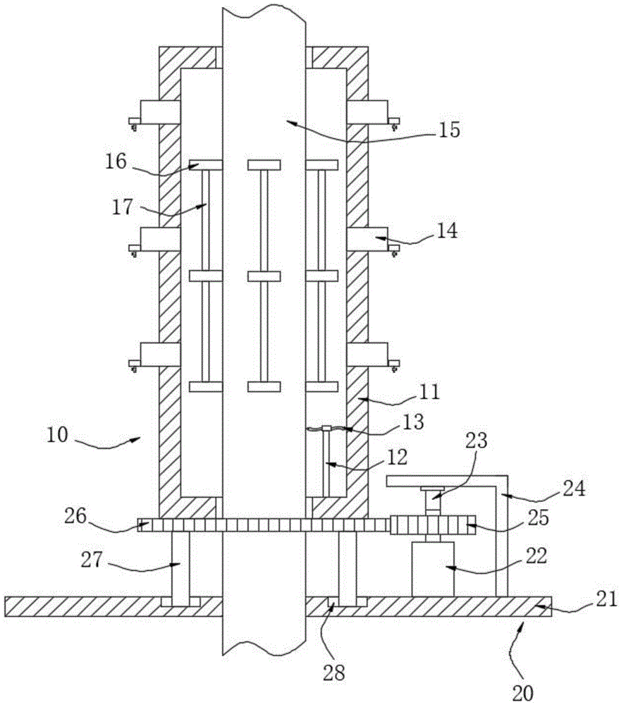
Fig. 1 is a schematic structural view of the present invention;
FIG. 2 is a schematic top view of the chimney according to the present invention;
fig. 3 is a schematic top view of the supporting plate of the present invention;
fig. 4 is a schematic view of the internal structure of the ventilation pipe of the present invention.
In the figure: 10. a body assembly; 11. a sleeve; 12. a first rod body; 13. a fan; 14. a vent pipe; 15. a chimney; 16. a copper heat-conducting sheet; 17. a copper heat conducting rod; 20. a rotating assembly; 21. a support plate; 22. a motor; 23. a second rod body; 24. an L-shaped plate; 25. a first gear; 26. a second gear; 27. a slider; 28. an annular chute; 30. a guard assembly; 31. a blind groove; 32. a rubber block; 33. filtering with a screen; 34. a handle; 35. absorbent cotton; 36. a housing; 37. a water outlet pipe; 38. and (4) a valve.
Detailed Description
The technical solutions in the embodiments of the present invention will be described clearly and completely with reference to the accompanying drawings in the embodiments of the present invention, and it is obvious that the described embodiments are only some embodiments of the present invention, not all embodiments. Based on the embodiments in the present invention, all other embodiments obtained by a person skilled in the art without creative work belong to the protection scope of the present invention.
Examples
Referring to fig. 1-4, the present invention provides a technical solution: a stove chimney directly-heated air heater comprises a main body assembly 10, a rotating assembly 20 and a protection assembly 30, wherein the main body assembly 10 comprises a sleeve 11, a fan 13, a ventilation pipe 14, a chimney 15, a copper heat-conducting fin 16 and a copper heat-conducting rod 17;
the rotating assembly 20 includes a support plate 21, a motor 22, a first gear 25 and a second gear 26;
the inside wall of sleeve 11 is provided with fan 13, sleeve 11's inside wall has run through chimney 15, the even welding of outside wall of chimney 15 has copper conducting strip 16, the adjacent one side of two adjacent copper conducting strips 16 has all welded copper conducting rod 17, sleeve 11's bottom welding has second gear 26, second gear 26's inside wall is run through to chimney 15's outside wall, second gear 26's lower surface is provided with backup pad 21, the last surface mounting of backup pad 21 has motor 22, motor 22's output shaft outside welding has first gear 25, the outside wall meshing of first gear 25 is connected in second gear 26's lateral wall, sleeve 11's even intercommunication of lateral wall has ventilation pipe 14, main part assembly 10's lower surface has rotating assembly 20, main part assembly 10's inside has protective assembly 30.
In this embodiment, specifically: the body assembly 10 further includes a first shaft 12;
a first rod 12 is installed on the outer side wall of the fan 13, and the bottom of the first rod 12 is welded on the inner bottom wall of the sleeve 11; the fan 13 is supported by the first lever 12.
In this embodiment, specifically: the rotating assembly 20 further comprises a second rod 23, an L-shaped plate 24, a sliding block 27 and an annular sliding groove 28;
an L-shaped plate 24 is welded on the upper surface of the supporting plate 21, a second rod body 23 is welded on the top of an output shaft of the motor 22, and the top of the second rod body 23 is rotatably connected to the lower surface of the L-shaped plate 24 through a bearing; the output shaft of the motor 22 is limited by the second rod 23 and the L-shaped plate 24, so that the output shaft of the motor 22 is prevented from shaking too much, and the first gear 25 and the second gear 26 cannot be meshed.
In this embodiment, specifically: an annular sliding groove 28 is formed in the upper surface of the supporting plate 21, two sliding blocks 27 are connected to the inside of the annular sliding groove 28 in a sliding mode, the top of each sliding block 27 is welded to the lower surface of the corresponding second gear 26, and the outer side wall of the chimney 15 is welded to the inner side wall of the supporting plate 21; the second gear 26 is supported and limited by the cooperation of the annular sliding groove 28 and the sliding block 27.
In this embodiment, specifically: the protection component 30 comprises a blind groove 31, a rubber block 32, a filter screen 33, a handle 34, absorbent cotton 35, a shell 36, a water outlet pipe 37 and a valve 38;
a filter screen 33 is arranged on the inner side wall of the ventilation pipe 14, and a handle 34 is welded on one side of the outer side wall of the filter screen 33; impurities in the blown air are filtered through the filter screen 33, which is beneficial to the cleanness of the air in the room.
In this embodiment, specifically: two blind grooves 31 are formed in the inner side wall of the ventilation pipe 14, rubber blocks 32 are bonded to the inner side wall of each blind groove 31, and one adjacent side of each rubber block 32 is attached to the outer side wall of the filter screen 33; when the filter screen 33 needs to be taken out and replaced, the handle 34 is pressed downwards, the handle 34 drives the filter screen 33 to press the rubber block 32 downwards, and then the filter screen 33 is taken out.
In this embodiment, specifically: the inner side wall of the ventilation pipe 14 is adhered with absorbent cotton 35; moisture in the blow-out gas can be sucked out by the absorbent cotton 35.
In this embodiment, specifically: a shell 36 is welded on one side of the outer side wall of the ventilation pipe 14, the lower surface of the shell 36 is communicated with a water outlet pipe 37, and a valve 38 is installed on the outer side wall of the water outlet pipe 37; when the water absorbed by the absorbent cotton 35 overflows due to excessive water, the water flows into the shell 36, and is prevented from being directly sprayed into a room, so that the waste of water resources is reduced.
In this embodiment, specifically: the fan 13 is model NXK51 and the motor 22 is model YN 60.
In this embodiment, specifically: a switch set for controlling the on and off of the fan 13 and the motor 22 is installed at one side of the supporting plate 21, and the switch set is connected with an external commercial power to supply power to the fan 13 and the motor 22.
Working principle or structural principle, when in use, the heat of the chimney 15 is absorbed by the copper heat conducting sheet 16 and is transmitted to the copper heat conducting rod 17, the fan 13 is started by the switch group, the fan 13 dissipates the heat of the copper heat conducting sheet 16 and the copper heat conducting rod 17 and blows the heat to the ventilation pipe 14 along with the air, so as to heat the room, the switch group is used for starting the motor 22, the output shaft of the motor 22 drives the first gear 25 to rotate, the first gear 25 drives the second gear 26 to rotate, the second gear 26 drives the sleeve 11 to rotate, the sleeve 11 drives the fan 13 to rotate, so as to dissipate the heat of the plurality of copper heat conducting sheets 16, so that the cost is saved, the fan 13 is supported by the first rod body 12, the second gear 26 is limited and supported by the mutual matching of the annular sliding groove 28 and the sliding block 27, and the output shaft of the motor 22 is limited by the second rod body 23, prevent that motor 22's range of rocking is too big, and then can't make first gear 25 and the meshing of second gear 26, inside through at ventilation pipe 14 sets up filter screen 33, can effectually filter the impurity in the air that blows out, prevent to rust because of chimney 15 live time overlength and fall the lacquer, impurity blows to the room along with the air, and then causes the pollution to the room environment, through setting up cotton 35 that absorbs water, can absorb the moisture in the air, prevent on the one hand that the room from weing, on the other hand can carry out the reutilization to the water of collecting.
Although embodiments of the present invention have been shown and described, it will be appreciated by those skilled in the art that changes, modifications, substitutions and alterations can be made in these embodiments without departing from the principles and spirit of the invention, the scope of which is defined in the appended claims and their equivalents.