CN215001330U - Novel multifunctional solar street lamp - Google Patents
Novel multifunctional solar street lamp Download PDFInfo
- Publication number
- CN215001330U CN215001330U CN202120344672.XU CN202120344672U CN215001330U CN 215001330 U CN215001330 U CN 215001330U CN 202120344672 U CN202120344672 U CN 202120344672U CN 215001330 U CN215001330 U CN 215001330U
- Authority
- CN
- China
- Prior art keywords
- fixedly connected
- groups
- water
- storage tank
- sets
- Prior art date
- Legal status (The legal status is an assumption and is not a legal conclusion. Google has not performed a legal analysis and makes no representation as to the accuracy of the status listed.)
- Expired - Fee Related
Links
Images

Classifications
-
- Y—GENERAL TAGGING OF NEW TECHNOLOGICAL DEVELOPMENTS; GENERAL TAGGING OF CROSS-SECTIONAL TECHNOLOGIES SPANNING OVER SEVERAL SECTIONS OF THE IPC; TECHNICAL SUBJECTS COVERED BY FORMER USPC CROSS-REFERENCE ART COLLECTIONS [XRACs] AND DIGESTS
- Y02—TECHNOLOGIES OR APPLICATIONS FOR MITIGATION OR ADAPTATION AGAINST CLIMATE CHANGE
- Y02A—TECHNOLOGIES FOR ADAPTATION TO CLIMATE CHANGE
- Y02A20/00—Water conservation; Efficient water supply; Efficient water use
- Y02A20/108—Rainwater harvesting
-
- Y—GENERAL TAGGING OF NEW TECHNOLOGICAL DEVELOPMENTS; GENERAL TAGGING OF CROSS-SECTIONAL TECHNOLOGIES SPANNING OVER SEVERAL SECTIONS OF THE IPC; TECHNICAL SUBJECTS COVERED BY FORMER USPC CROSS-REFERENCE ART COLLECTIONS [XRACs] AND DIGESTS
- Y02—TECHNOLOGIES OR APPLICATIONS FOR MITIGATION OR ADAPTATION AGAINST CLIMATE CHANGE
- Y02B—CLIMATE CHANGE MITIGATION TECHNOLOGIES RELATED TO BUILDINGS, e.g. HOUSING, HOUSE APPLIANCES OR RELATED END-USER APPLICATIONS
- Y02B20/00—Energy efficient lighting technologies, e.g. halogen lamps or gas discharge lamps
- Y02B20/72—Energy efficient lighting technologies, e.g. halogen lamps or gas discharge lamps in street lighting
Landscapes
- Non-Portable Lighting Devices Or Systems Thereof (AREA)
Abstract
The utility model discloses a novel multifunctional solar street lamp, which comprises a bottom plate, wherein the top of the bottom plate is fixedly connected with a water storage tank, the bottom of the surface of the water storage tank is provided with a drain pipe, the annular surface of the drain pipe is provided with a water stop valve, the middle of the top of the water storage tank is fixedly connected with a vertical support column, a threaded rod rotates to drive a limit block to lift up and down, a rain shelter is driven to unfold through the cooperation of a first connecting shaft, a second connecting shaft, a movable rod, a support rod and a fixed shaft to shield rain, when the street lamp is not used, the threaded rod rotates reversely, the rain shelter can be contracted, the solar panel can not be influenced to absorb sunlight, the solar panel can be prevented from being damaged due to long-time rain washing, rainwater falls into the rain shelter, enters the inside of a connecting seat through a water inlet, then is fed into a water collecting tank through a water outlet and a connecting pipe, and finally is fed into the water storage tank through a water inlet pipe to be stored, the rainwater is collected and used, and the utilization of resources is improved.
Description
Technical Field
The utility model belongs to the technical field of the solar street lamp, specifically be a novel multi-functional solar street lamp.
Background
The solar street lamp is powered by a crystalline silicon solar cell, a maintenance-free valve-controlled sealed storage battery stores electric energy, an ultra-high-brightness LED lamp is used as a light source and is controlled by an intelligent charging and discharging controller to replace the traditional street lamp for public power illumination, a solar cell panel of a common solar street lamp is installed in the external environment and is washed by rainwater for a long time in rainy days, damage is easily caused, and the rainwater can be collected and recycled as important water resources, so that the novel multifunctional solar street lamp is provided.
SUMMERY OF THE UTILITY MODEL
An object of the utility model is to provide a novel multi-functional solar street lamp to the solar cell panel who proposes in solving above-mentioned background receives the rainwash for a long time, causes the problem of damage easily.
In order to achieve the above object, the utility model provides a following technical scheme: a novel multifunctional solar street lamp comprises a bottom plate, wherein a water storage tank is fixedly connected to the top of the bottom plate, a water discharge pipe is arranged at the bottom of the surface of the water storage tank, a water stop valve is arranged on the annular surface of the water discharge pipe, a vertical support column is fixedly connected to the middle of the top of the water storage tank, a stabilizing sleeve is sleeved at the bottom of the surface of the support column, four groups of inclined support plates are fixedly connected to the bottom of the surface of the stabilizing sleeve in an annular array manner, the bottoms of the four groups of support plates are fixedly connected with the top of the water storage tank, two groups of bent lighting lamp brackets are fixedly connected to the tops of the left side and the right side of the support column, two groups of lighting lamps are fixedly connected to the bottoms of the two groups of lighting lamp brackets, a transmission box is fixedly connected to the top of the support column, a transverse fixing plate is arranged at the top of the lighting lamp brackets on the right side, and the left side of the fixing plate is fixedly connected with the top of the right side of the support column, the solar energy rain protection device is characterized in that a driving motor is fixedly connected to the right side of the top of the fixing plate, a connecting rod is arranged on the left side of the driving motor, two groups of fixing rods are fixedly connected to the top of the left side and the bottom of the transmission case, the solar cell panel is fixedly connected to the left ends of the fixing rods, a connecting seat is fixedly connected to the top of the transmission case, and a rain shelter is arranged at the top of the connecting seat.
Preferably, the inner chamber bottom fixedly connected with water catch bowl of transmission case, two sets of first fixed blocks of fixedly connected with in the middle of the one side that water catch bowl and transmission case inner chamber are close to each other, it is two sets of one side swing joint that first fixed block is close to each other has vertical first dwang, the surperficial top of first dwang is equipped with first conical gear, first conical gear's bottom right side be equipped with first conical gear assorted second bevel gear, the horizontal second dwang of right side fixedly connected with of second bevel gear, the right side that the transmission case was not run through to the one end that the connecting rod is not connected with driving motor and the right-hand member fixed connection of second dwang, the inner chamber left side of transmission case is equipped with vertical connecting pipe, and the bottom of connecting pipe runs through the inner chamber that the top left side of water catch bowl extends to the water catch bowl.
Preferably, be equipped with vertical inlet tube in the middle of the inner chamber of support column, and the top of inlet tube runs through the top of support column and the bottom of transmission case and water catch bowl extends to the inner chamber bottom of water catch bowl, the bottom of inlet tube runs through the bottom of support column and the top of storage water tank extends to the inner chamber of storage water tank.
Preferably, the inner chamber center department of connecting seat is equipped with first rotation pole assorted passageway, the bottom left side of connecting seat is equipped with down the mouth of a river, the top left side that the transmission case was run through on the top of connecting pipe is connected with down the mouth of a river, the top of connecting seat is equipped with a plurality of water inlets of group, the two sets of second fixed blocks of top left and right sides fixedly connected with of connecting seat, it is two sets of the surface through connection of second fixed block has two sets of fixed axles.
Preferably, the center department of rainshelter is equipped with vertical threaded rod, the top of first pivot pole runs through the top in the middle of the top of first fixed block, transmission case and the bottom fixed connection of connecting seat and threaded rod, the cover has connect the stopper in the middle of the surface of threaded rod, the stopper all around fixedly connected with four groups of first connecting blocks, four groups first connecting block through connection has four groups of first connecting axles.
Preferably, the inner wall of rainshelter is four group's bracing pieces of annular array fixedly connected with, and four groups the bottom of bracing piece runs through four groups the top and four groups of second fixed block the fixed axle rotates to be connected, four groups fixedly connected with four groups of second connecting blocks, four groups in the middle of the one side that the bracing piece is close to each other second connecting block through connection has four groups of second connecting axles, four groups first connecting axle and four groups be equipped with four groups of movable rods between the second connecting axle.
Compared with the prior art, the beneficial effects of the utility model are that:
1. when raining, the driving motor drives the connecting rod, the second rotating rod and the second bevel gear to rotate, the second bevel gear is meshed with the first bevel gear, so that the first bevel gear drives the first rotating rod and the threaded rod to rotate, the limiting block is driven to lift up and down, the movable rod is driven to rotate and expand through the cooperation of the first connecting shaft and the second connecting shaft, the supporting rod is matched with the fixed shaft to drive the rain shelter to expand for rain sheltering, when the solar shelter is not used, the driving motor drives the threaded rod to rotate reversely, the rain shelter can be contracted, the solar panel cannot be influenced to absorb sunlight, the damage caused by long-time rain washing to the solar panel can be avoided, and the service life of the solar panel is prolonged;
2. the rainwater falls into the rainshelter, and enters the connecting seat through the water inlet hole, and then is sent into the water collecting tank through the water outlet and the connecting pipe, and finally the water in the water collecting tank can be stored in the water storage tank through the inlet tube, so that the rainwater is collected and used, and the utilization of resources is improved.
Drawings
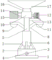
FIG. 1 is a schematic structural view of the present invention;
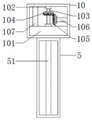
FIG. 2 is a schematic structural view of the support pillar and the transmission case of the present invention;
fig. 3 is the schematic view of the structure of the connecting seat and the rain shelter of the present invention.
In the figure: 1 bottom plate, 2 storage water tanks, 3 drain pipes, 4 water stop valves, 5 support columns, 51 water inlet pipes, 6 stabilizing sleeves, 7 support frames, 8 lighting lamp holders, 9 lighting lamps, 10 transmission boxes, 101 water collecting tanks, 102 first fixing blocks, 103 first rotating rods, 104 first bevel gears, 105 second bevel gears, 106 second rotating rods, 107 connecting pipes, 11 fixing plates, 12 driving motors, 13 connecting rods, 14 fixing rods, 15 solar cell panels, 16 connecting seats, 161 channels, 162 water outlets, 163 water inlet holes, 164 second fixing blocks, 165 fixing shafts, 17 rain shelters, 171 threaded rods, 172 limiting blocks, 173 first connecting blocks, 174 first connecting shafts, 175 supporting rods, 176 second connecting blocks, 177 second connecting shafts and 178 movable rods.
Detailed Description
The technical solutions in the embodiments of the present invention will be described clearly and completely with reference to the accompanying drawings in the embodiments of the present invention, and it is obvious that the described embodiments are only some embodiments of the present invention, not all embodiments. Based on the embodiments in the present invention, all other embodiments obtained by a person skilled in the art without creative work belong to the protection scope of the present invention.
Referring to fig. 1-3, the present invention provides a technical solution: a novel multifunctional solar street lamp comprises a bottom plate 1, wherein the top of the bottom plate 1 is fixedly connected with a water storage tank 2, the bottom of the surface of the water storage tank 2 is provided with a water discharge pipe 3, the annular surface of the water discharge pipe 3 is provided with a water stop valve 4, the middle of the top of the water storage tank 2 is fixedly connected with a vertical support column 5, the bottom of the surface of the support column 5 is sleeved with a stabilizing sleeve 6, the bottom of the surface of the stabilizing sleeve 6 is fixedly connected with four groups of inclined support plates 7 in an annular array manner, the bottoms of the four groups of support plates 7 are fixedly connected with the top of the water storage tank 2, the tops of the left side and the right side of the support column 5 are fixedly connected with two groups of bent illuminating lamp brackets 8, the bottoms of the two groups of illuminating lamp brackets 8 are fixedly connected with two groups of illuminating lamps 9, the top of the support column 5 is fixedly connected with a transmission case 10, and the top of the right side of the illuminating lamp brackets 8 is provided with a transverse fixing plate 11, and the left side of fixed plate 11 and the right side top fixed connection of support column 5, the top right side fixedly connected with driving motor 12 of fixed plate 11, driving motor 12's left side is equipped with connecting rod 13, the left side top of transmission case 10 and two sets of dead levers 14 of bottom fixedly connected with, it is two sets of the left end fixedly connected with solar cell panel 15 of dead lever 14, the top fixedly connected with connecting seat 16 of transmission case 10, the top of connecting seat 16 is equipped with rainshelter 17.
Referring to fig. 1 and 2, a water collection tank 101 is fixedly connected to the bottom of an inner cavity of the transmission case 10, two sets of first fixing blocks 102 are fixedly connected to the middle of one side of the water collection tank 101, which is close to the inner cavity of the transmission case 10, one side of the two sets of first fixing blocks 102, which is close to each other, is movably connected to a vertical first rotating rod 103, a first bevel gear 104 is arranged on the top surface of the first rotating rod 103, a second bevel gear 105 matched with the first bevel gear 104 is arranged on the right side of the bottom of the first bevel gear 104, a horizontal second rotating rod 106 is fixedly connected to the right side of the second bevel gear 105, one end of the connecting rod 13, which is not connected to the driving motor 12, penetrates through the right end of the transmission case 10 and is fixedly connected to the right end of the second rotating rod 106, a vertical connecting pipe 107 is arranged on the left side of the inner cavity of the transmission case 10, and the bottom end of the connecting pipe 107 penetrates through the left side of the top of the water collection tank 101 and extends to the inner cavity of the water collection tank 101, the driving motor 12 drives the connecting rod 13, the second rotating rod 106 and the second bevel gear 105 to rotate, and the first bevel gear 104 drives the first rotating rod 103 to rotate due to the meshing connection between the second bevel gear 105 and the first bevel gear 104;
referring to fig. 1 and 2, a vertical water inlet pipe 51 is arranged in the middle of an inner cavity of the support pillar 5, the top end of the water inlet pipe 51 penetrates through the top of the support pillar 5 and the bottom of the transmission case 10 and the water collection tank 101 to extend to the bottom of the inner cavity of the water collection tank 101, the bottom end of the water inlet pipe 51 penetrates through the bottom of the support pillar 5 and the top of the water storage tank 2 to extend to the inner cavity of the water storage tank 2, and water in the water collection tank 101 can be sent into the water storage tank 2 through the water inlet pipe 51 to be stored;
referring to fig. 2 and 3, a channel 161 matched with the first rotating rod 103 is arranged at the center of an inner cavity of the connecting seat 16, a drain 162 is arranged at the left side of the bottom of the connecting seat 16, the top end of the connecting tube 107 penetrates through the left side of the top of the transmission case 10 to be connected with the drain 162, a plurality of sets of water inlet holes 163 are arranged at the top of the connecting seat 16, two sets of second fixing blocks 164 are fixedly connected to the left and right sides of the top of the connecting seat 16, two sets of fixing shafts 165 are connected to the surfaces of the two sets of second fixing blocks 164 in a penetrating manner, and water in the rain shelter 17 falls into the connecting seat 16 through the water inlet holes 163 and then is sent into the water collecting tank 101 through the drain 162 and the connecting tube 107;
referring to fig. 2 and 3, a vertical threaded rod 171 is disposed at the center of the canopy 17, the top end of the first rotating rod 103 penetrates through the top of the first fixed block 102, the middle of the top of the transmission case 10, and the bottom end of the connecting seat 16 and the threaded rod 171 are fixedly connected, a limiting block 172 is sleeved in the middle of the surface of the threaded rod 171, four groups of first connecting blocks 173 are fixedly connected around the limiting block 172, four groups of first connecting shafts 174 are connected through the four groups of first connecting blocks 173, four groups of supporting rods 175 are fixedly connected to the inner wall of the canopy 17 in an annular array, the bottoms of the four groups of supporting rods 175 penetrate through the tops of the four groups of second fixed blocks 164 and are rotatably connected to the four groups of fixed shafts 165, four groups of second connecting blocks 176 are fixedly connected to the middle of the side of the four groups of supporting rods 175 close to each other, four groups of second connecting shafts 177 are connected through the four groups of second connecting blocks 176, four groups of movable rods 178 are arranged between the four groups of first connecting shafts 174 and the four groups of second connecting shafts 177, the first rotating rods 103 drive the threaded rods 171 to rotate to drive the limiting blocks 172 to ascend and descend vertically, and the movable rods 178 are driven to extend and retract in a rotating mode through the cooperation of the first connecting shafts 174 and the second connecting shafts 177, so that the supporting rods 175 and the fixed shafts 165 are matched to rotate to drive the rain shelter 17 to expand or contract.
The working principle is as follows: when the rain sheltering shed is not used, the driving motor 12 drives the threaded rod 171 to reversely rotate, so that the rain sheltering shed 17 can be contracted, the solar cell panel 15 cannot be influenced to absorb sunlight, rainwater falls into the rain sheltering shed 17 and enters the connecting seat 16 through the water inlet 163, and then is sent into the connecting pipe of the water collecting tank 101 through the water outlets 162 and 107, finally, the water in the water collecting tank 101 can be fed into the water storage tank 2 through the water inlet pipe 51 for storage.
Although embodiments of the present invention have been shown and described, it will be appreciated by those skilled in the art that changes, modifications, substitutions and alterations can be made in these embodiments without departing from the principles and spirit of the invention, the scope of which is defined in the appended claims and their equivalents.
Claims (6)
Priority Applications (1)
| Application Number | Priority Date | Filing Date | Title |
|---|---|---|---|
| CN202120344672.XU CN215001330U (en) | 2021-02-07 | 2021-02-07 | Novel multifunctional solar street lamp |
Applications Claiming Priority (1)
| Application Number | Priority Date | Filing Date | Title |
|---|---|---|---|
| CN202120344672.XU CN215001330U (en) | 2021-02-07 | 2021-02-07 | Novel multifunctional solar street lamp |
Publications (1)
| Publication Number | Publication Date |
|---|---|
| CN215001330U true CN215001330U (en) | 2021-12-03 |
Family
ID=79145981
Family Applications (1)
| Application Number | Title | Priority Date | Filing Date |
|---|---|---|---|
| CN202120344672.XU Expired - Fee Related CN215001330U (en) | 2021-02-07 | 2021-02-07 | Novel multifunctional solar street lamp |
Country Status (1)
| Country | Link |
|---|---|
| CN (1) | CN215001330U (en) |
Cited By (2)
| Publication number | Priority date | Publication date | Assignee | Title |
|---|---|---|---|---|
| CN114429738A (en) * | 2022-02-14 | 2022-05-03 | 刘松玉 | Multifunctional propaganda device for civil engineering construction safety and use method thereof |
| CN119935212A (en) * | 2025-04-08 | 2025-05-06 | 山西省城乡规划设计研究院有限公司 | A geographic information collection device for national land space planning |
-
2021
- 2021-02-07 CN CN202120344672.XU patent/CN215001330U/en not_active Expired - Fee Related
Cited By (2)
| Publication number | Priority date | Publication date | Assignee | Title |
|---|---|---|---|---|
| CN114429738A (en) * | 2022-02-14 | 2022-05-03 | 刘松玉 | Multifunctional propaganda device for civil engineering construction safety and use method thereof |
| CN119935212A (en) * | 2025-04-08 | 2025-05-06 | 山西省城乡规划设计研究院有限公司 | A geographic information collection device for national land space planning |
Similar Documents
| Publication | Publication Date | Title |
|---|---|---|
| CN206207303U (en) | A kind of LED garden lamps of waterproof | |
| CN216203181U (en) | Intelligent street lamp pole with solar cell panel capable of automatically turning | |
| CN108657010A (en) | A kind of new-energy automobile charging pile | |
| CN216893651U (en) | Power generation sunlight room | |
| CN110594678A (en) | Municipal street lamp based on solar energy | |
| CN106229365B (en) | A kind of monocrystaline silicon solar cell piece for possessing high intensity | |
| CN210976725U (en) | Environment-friendly toilet | |
| CN113348971A (en) | Greenhouse for planting lucid ganoderma efficiently by agricultural light complementation and planting method | |
| CN211090923U (en) | Photovoltaic greenhouse top solar power station | |
| CN221428867U (en) | A monocrystalline silicon solar cell structure with good sealing performance | |
| CN217388643U (en) | Roof photovoltaic power generation device of industrial factory building | |
| CN109140369B (en) | High-building intelligent lighting equipment | |
| CN112482832B (en) | FRP integration intelligent movement bathroom | |
| CN113883483A (en) | Intelligent street lamp pole with solar cell panel capable of automatically turning | |
| CN116508619A (en) | An automatic irrigation equipment for potato intelligent cultivation | |
| CN108730888B (en) | A wind-solar complementary street light system | |
| CN210637944U (en) | Solar street lamp convenient to overhaul | |
| CN212342226U (en) | Liftable municipal publicity column | |
| CN108756309B (en) | An ecological energy-saving building | |
| CN220954895U (en) | Multifunctional sinking type parking space structure | |
| CN216565056U (en) | Unmanned cleaning equipment for solar panel | |
| CN119879152B (en) | Angle-adjustable solar street light | |
| CN207767603U (en) | A kind of emulation ecology tree being used in gardens with Air purification | |
| CN218921118U (en) | A photovoltaic greenhouse for crops | |
| CN204678713U (en) | High and the solar water heater that can rotate of a kind of daylight rate |
Legal Events
| Date | Code | Title | Description |
|---|---|---|---|
| GR01 | Patent grant | ||
| GR01 | Patent grant | ||
| CF01 | Termination of patent right due to non-payment of annual fee |
Granted publication date: 20211203 |
|
| CF01 | Termination of patent right due to non-payment of annual fee |