CN214993601U - Gate vent with overhaul function - Google Patents
Gate vent with overhaul function Download PDFInfo
- Publication number
- CN214993601U CN214993601U CN202121232302.3U CN202121232302U CN214993601U CN 214993601 U CN214993601 U CN 214993601U CN 202121232302 U CN202121232302 U CN 202121232302U CN 214993601 U CN214993601 U CN 214993601U
- Authority
- CN
- China
- Prior art keywords
- gate
- vent
- hole
- service function
- hydraulic hoist
- Prior art date
- Legal status (The legal status is an assumption and is not a legal conclusion. Google has not performed a legal analysis and makes no representation as to the accuracy of the status listed.)
- Active
Links
- 238000009434 installation Methods 0.000 claims abstract description 7
- 238000007789 sealing Methods 0.000 claims abstract description 6
- 210000000481 breast Anatomy 0.000 claims abstract description 5
- XLYOFNOQVPJJNP-UHFFFAOYSA-N water Substances O XLYOFNOQVPJJNP-UHFFFAOYSA-N 0.000 claims description 9
- 229910000831 Steel Inorganic materials 0.000 claims description 7
- 239000010959 steel Substances 0.000 claims description 7
- 238000009423 ventilation Methods 0.000 claims description 3
- 238000012423 maintenance Methods 0.000 abstract description 6
- 238000010586 diagram Methods 0.000 description 1
- 239000012466 permeate Substances 0.000 description 1
Images
Landscapes
- Barrages (AREA)
Abstract
The utility model discloses a gate air vent with overhaul function, the gate sets up in the gate slot, the top sealing connection of gate slot has the frame that is used for installing hydraulic hoist, hydraulic hoist is located the installation intracavity, and hydraulic hoist's hanging head links to each other with the lug of gate, include: the access hole is arranged in the breast wall at the downstream of the gate and is provided with a first end and a second end, the first end is provided with a plugging component, the first end extends into the mounting cavity, and the second end is communicated with the flow channel; and the vent hole is provided with a third end and a fourth end, the third end is communicated with the access hole, and the fourth end extends upwards to the outside of the dam body. The utility model discloses the structure is ingenious, saves space, can normally ventilate and provide under the prerequisite of maintenance condition after guaranteeing the gate door, and the whole security that fully reduces the concrete structure intensity improves the gate structure.
Description
Technical Field
The utility model belongs to the technical field of the gate air vent technical field among the hydraulic and hydroelectric engineering and specifically relates to a gate air vent with overhaul function is related to.
Background
When the down-the-hole gate cannot be adequately vented behind the gate, a vent must be placed immediately atop the downstream opening of the gate, with the vent outlet above the highest water level that may occur, as required by the gate design code. For a gate valve type gate, as a gate hoist platform is arranged inside a dam body, the platform elevation is lower than the designed water level in front of the dam, in order to prevent water from gushing from the top of a gate slot, a completely sealed hydraulic hoist frame is generally adopted to be arranged at the top of the gate slot, the hydraulic hoist is arranged at the center of the frame, a hanging head of the hoist is connected with a gate lifting lug, the gate is always hung in the water, the frame and a gate embedded part are connected by a high-strength bolt, a sealing ring is arranged in the middle of the frame, and therefore, the hoist platform cannot permeate water. However, the arrangement mode has the problem of difficult maintenance behind the gate, because the frame is closed, people cannot go through the gate slot to the flow channel underground, if the manhole is opened from the frame, the damage to the frame structure is large, only the manhole can be reserved in the concrete of the breast wall at the downstream of the gate, the area of the manhole and the vent hole is large, the strength of the concrete structure is weakened, and the structure safety is influenced.
Disclosure of Invention
In order to solve the problem, the utility model provides a gate air vent with overhaul function specifically can take following technical scheme:
gate air vent with overhaul function, the gate sets up in the gate slot, the top sealing connection of gate slot has the frame that is used for installing hydraulic hoist, hydraulic hoist is located the installation intracavity, and hydraulic hoist's hanging head links to each other with the lug of gate, include
The access hole is arranged in the breast wall at the downstream of the gate and is provided with a first end and a second end, the first end is provided with a plugging component, the first end extends into the mounting cavity, and the second end is communicated with the flow channel;
and the vent hole is provided with a third end and a fourth end, the third end is communicated with the access hole, and the fourth end extends upwards to the outside of the dam body.
The manhole is a vertically arranged steel pipe, the vent hole is a steel pipe arranged at the middle upper part of the manhole, and the joint of the vent hole and the manhole forms a kidney-shaped outer joint structure.
The aperture of the access hole simultaneously meets the requirements of access space and ventilation capacity.
The first end is 300mm higher than the bottom surface of the mounting cavity.
The plugging assembly comprises a flange arranged at the first end and a flange cover connected with the flange through bolts.
And the fourth end of the vent hole is higher than the highest water level in front of the dam.
And the top of the mounting cavity is provided with an overhauling hanging box opposite to the overhauling hole.
And an air supply branch pipe extending into the door groove is arranged at the upper part of the access hole.
The utility model provides a gate air vent with overhaul function, the structure is ingenious, saves space, can normally ventilate and provide under the prerequisite of overhauing the condition after guaranteeing the gate door, and the whole security that fully reduces the concrete structure intensity improves the gate structure.
Drawings
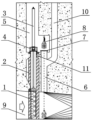
Fig. 1 is a schematic structural diagram of the present invention.
Detailed Description
The embodiments of the present invention will be described in detail with reference to the accompanying drawings, and the embodiments are implemented on the premise of the technical solution of the present invention, and detailed implementation is given, but the scope of the present invention is not limited to the following embodiments.
As shown in figure 1, the gate vent with overhaul function of the utility model can be used in the design of a plug board valve type gate, such as a power station inlet quick door, a pumped storage tail water accident door and the like. Among the above-mentioned operating mode, gate 1 is installed in gate slot 2, and the top sealing connection of gate slot 2 has the frame 4 that is used for installing hydraulic hoist 3, and hydraulic hoist 3 is located installation cavity 5, and hydraulic hoist 3's hanging head links to each other with gate 1's lug, buries the steel pipe that has set up perpendicularly as access hole 6 underground in the breast wall concrete in gate 1 low reaches, and its aperture size is set for according to operating condition, should satisfy maintenance space requirement and air flow requirement simultaneously at least. The top (namely the first end) of the access hole 6 extends into the installation cavity 5 and is 300mm higher than the bottom surface of the installation cavity 5, a flange is welded on the access hole, and a sealing flange cover 7 connected by bolts is arranged on the flange under normal conditions and is used for plugging the access hole 6; when the maintenance is needed, the flange cover 7 is opened, so that the maintenance personnel can go in and out the maintenance hole 6. Furthermore, the top of the installation cavity 5 is provided with an overhaul hanging box 8 which is right opposite to the overhaul hole 6, so that the overhaul hanging box is convenient for the overhaul personnel to take when getting in and out. The bottom (i.e. the second end) of the access hole 6 extends to the top of the flow channel 9, so that the access hole 6 is communicated with the flow channel 9, and a maintainer can take the access hanging box 8 to reach the bottom of the flow channel 9 through the access hole 6 to carry out work. A vent hole 10 is also arranged on one side of the access hole 6, the vent hole 10 is a vertical steel pipe with an elbow at the bottom, and the tail end (namely, the third end) of the elbow is communicated with the side wall of the middle upper part of the access hole 6, so that the vent hole 10 is connected with the access hole 6 in a Bu-shaped external connection mode; the top end (i.e. the fourth end) of the vertical steel pipe of the vent hole 10 extends up to a position outside the dam body higher than the highest water level in front of the dam so as to ensure sufficient ventilation behind the down-the-hole gate. In order to prevent the top of the gate from forming vacuum when the gate 1 is closed quickly, an air supply branch pipe 11 extending into the gate slot 2 is also arranged at the upper part of the access hole 6.
It should be noted that in the description of the present invention, terms of orientation or positional relationship such as "front", "rear", "left", "right", "vertical", "horizontal", "inner", "outer", etc., are based on the orientation or positional relationship shown in the drawings, and are only for convenience of description and simplification of description, but do not indicate or imply that the device or element referred to must have a specific orientation, be constructed and operated in a specific orientation, and thus, should not be construed as limiting the present invention.
Claims (8)
1. The utility model provides a gate air vent with overhaul function, the gate sets up in the gate slot, the top sealing connection of gate slot has the frame that is used for installing hydraulic hoist machine, hydraulic hoist machine is located the installation intracavity, and hydraulic hoist machine's hanging head links to each other its characterized in that with the lug of gate: comprises that
The access hole is arranged in the breast wall at the downstream of the gate and is provided with a first end and a second end, the first end is provided with a plugging component, the first end extends into the mounting cavity, and the second end is communicated with the flow channel;
and the vent hole is provided with a third end and a fourth end, the third end is communicated with the access hole, and the fourth end extends upwards to the outside of the dam body.
2. A gate vent with service function as claimed in claim 1, wherein: the manhole is a vertically arranged steel pipe, the vent hole is a steel pipe arranged at the middle upper part of the manhole, and the joint of the vent hole and the manhole forms a kidney-shaped outer joint structure.
3. A gate vent with service function as claimed in claim 2, wherein: the aperture of the access hole simultaneously meets the requirements of access space and ventilation capacity.
4. A gate vent with service function as claimed in claim 1, wherein: the first end is 300mm higher than the bottom surface of the mounting cavity.
5. A gate vent with service function as claimed in claim 1, wherein: the plugging assembly comprises a flange arranged at the first end and a flange cover connected with the flange through bolts.
6. A gate vent with service function as claimed in claim 1, wherein: and the fourth end of the vent hole is higher than the highest water level in front of the dam.
7. A gate vent with service function as claimed in claim 1, wherein: and the top of the mounting cavity is provided with an overhauling hanging box opposite to the overhauling hole.
8. A gate vent with service function as claimed in claim 1, wherein: and an air supply branch pipe extending into the door groove is arranged at the upper part of the access hole.
Priority Applications (1)
| Application Number | Priority Date | Filing Date | Title |
|---|---|---|---|
| CN202121232302.3U CN214993601U (en) | 2021-06-03 | 2021-06-03 | Gate vent with overhaul function |
Applications Claiming Priority (1)
| Application Number | Priority Date | Filing Date | Title |
|---|---|---|---|
| CN202121232302.3U CN214993601U (en) | 2021-06-03 | 2021-06-03 | Gate vent with overhaul function |
Publications (1)
| Publication Number | Publication Date |
|---|---|
| CN214993601U true CN214993601U (en) | 2021-12-03 |
Family
ID=79086054
Family Applications (1)
| Application Number | Title | Priority Date | Filing Date |
|---|---|---|---|
| CN202121232302.3U Active CN214993601U (en) | 2021-06-03 | 2021-06-03 | Gate vent with overhaul function |
Country Status (1)
| Country | Link |
|---|---|
| CN (1) | CN214993601U (en) |
Cited By (1)
| Publication number | Priority date | Publication date | Assignee | Title |
|---|---|---|---|---|
| CN113174905A (en) * | 2021-06-03 | 2021-07-27 | 黄河勘测规划设计研究院有限公司 | Gate vent with overhaul function |
-
2021
- 2021-06-03 CN CN202121232302.3U patent/CN214993601U/en active Active
Cited By (1)
| Publication number | Priority date | Publication date | Assignee | Title |
|---|---|---|---|---|
| CN113174905A (en) * | 2021-06-03 | 2021-07-27 | 黄河勘测规划设计研究院有限公司 | Gate vent with overhaul function |
Similar Documents
| Publication | Publication Date | Title |
|---|---|---|
| CN201473933U (en) | Combined layout structure of tailwater accident gate and tailwater surge tank of pumped storage power station | |
| CN211973764U (en) | Anti-overflow well lid and municipal sewage system | |
| CN113174905A (en) | Gate vent with overhaul function | |
| CN206667364U (en) | A kind of novel submerged pumping plant | |
| CN204126003U (en) | The comprehensive interim waterworks for firefighting of a kind of packaged type | |
| CN208535565U (en) | Compressed air system drainage component and compressed air system | |
| CN203603977U (en) | Waterproof and fireproof air-tight door for mine | |
| CN213387361U (en) | Elevator prevention of seepage water sill | |
| CN218323043U (en) | Integrated negative pressure pump station for collecting negative pressure sewage | |
| CN210177443U (en) | Hydraulic vertical open-close type integrated pump brake | |
| CN210597539U (en) | Integrated sewage lifting pump station | |
| CN212772231U (en) | Structure of gate for preventing moisture gushing accident | |
| CN215888017U (en) | Waterproof safe light curtain device of railway banister | |
| CN209722910U (en) | Device for temporarily plugging gate shaft of tunnel body of diversion tunnel | |
| CN112196008A (en) | Water intake with maintenance cover and maintenance method | |
| CN222477387U (en) | Hydraulic building and gate valve type quick gate and hoist arrangement structure | |
| CN215672755U (en) | Self-drainage and pumping combined bidirectional dry submersible pump station | |
| CN221372252U (en) | Urban comprehensive pipe rack gas cabin water collection system | |
| CN101914908B (en) | Water stop rubber protection device for flat steel gate | |
| CN112554142B (en) | Cover type plane gate and use method thereof | |
| CN216664215U (en) | Submarine pipe tunnel construction seal pot device | |
| CN215715838U (en) | Large-scale pump station water pump overhauls drainage device | |
| CN204312782U (en) | A kind of double-side opening buoyancy tank flap valve valve | |
| CN216811780U (en) | Emergency flood-proof door for construction of connecting channel | |
| CN206386147U (en) | A kind of anti-contrary wind of underground coal mine protrusion-dispelling air door, air leakage preventing device |
Legal Events
| Date | Code | Title | Description |
|---|---|---|---|
| GR01 | Patent grant | ||
| GR01 | Patent grant |