CN214991736U - Heat treatment device for machining and forging cutter - Google Patents
Heat treatment device for machining and forging cutter Download PDFInfo
- Publication number
- CN214991736U CN214991736U CN202121340251.6U CN202121340251U CN214991736U CN 214991736 U CN214991736 U CN 214991736U CN 202121340251 U CN202121340251 U CN 202121340251U CN 214991736 U CN214991736 U CN 214991736U
- Authority
- CN
- China
- Prior art keywords
- heat treatment
- shell
- plate
- treatment device
- sliding
- Prior art date
- Legal status (The legal status is an assumption and is not a legal conclusion. Google has not performed a legal analysis and makes no representation as to the accuracy of the status listed.)
- Expired - Fee Related
Links
- 238000010438 heat treatment Methods 0.000 title claims abstract description 40
- 238000005242 forging Methods 0.000 title claims description 10
- 238000003754 machining Methods 0.000 title claims description 10
- 230000005540 biological transmission Effects 0.000 claims description 3
- 238000005096 rolling process Methods 0.000 claims description 2
- 244000309464 bull Species 0.000 abstract description 5
- 238000004519 manufacturing process Methods 0.000 abstract description 5
- 238000007669 thermal treatment Methods 0.000 abstract description 3
- 238000005516 engineering process Methods 0.000 abstract description 2
- 206010053615 Thermal burn Diseases 0.000 description 2
- 230000009286 beneficial effect Effects 0.000 description 1
- 238000001816 cooling Methods 0.000 description 1
- 238000010586 diagram Methods 0.000 description 1
- 239000000463 material Substances 0.000 description 1
- 239000002184 metal Substances 0.000 description 1
- 238000000034 method Methods 0.000 description 1
- 238000004321 preservation Methods 0.000 description 1
- 239000007787 solid Substances 0.000 description 1
- 239000002699 waste material Substances 0.000 description 1
Images

Landscapes
- Forging (AREA)
Abstract
The utility model relates to a cutter processing technology field just discloses a forged heat treatment device of cutter processing, including casing and heating pipe, it is a plurality of the heating pipe is all from a left side to the right side fixed setting in proper order in the inside upper end of casing, logical groove has all been seted up to the middle part both sides wall of casing, two fixed being provided with the fixed plate between leading to the groove, the spout has been seted up to the upper surface of fixed plate, the upper surface of fixed plate is provided with the backup pad, slider and spout sliding connection are passed through at the lower surface middle part of backup pad, the both sides of backup pad are inside all to be provided with the rotor plate, two through the bull stick rotation a plurality of sword grooves have all been seted up to the upper surface of rotor plate, the bar mouth has been seted up to the lower surface of spout, the inside lower extreme of casing is provided with the drive mechanism that drives slider reciprocating motion. The utility model discloses can prevent that personnel from scalding and can carry out continuous thermal treatment work, it is extravagant to reduce the time, improves production efficiency.
Description
Technical Field
The utility model relates to a cutter processing technology field especially relates to a forged heat treatment device of cutter processing.
Background
The heat treatment refers to a metal hot working process for obtaining expected structure and performance by means of heating, heat preservation and cooling of materials in a solid state, and the heat treatment is an indispensable processing link in the machining and forging of a cutter.
Traditional forged heat treatment device of cutter processing generally needs the manual work to put into the device with the cutter, takes out by the manual work after the heat treatment is accomplished again, because the internal temperature is higher when heat treatment furnace operation, causes personnel's scald very easily, and during unloading, it is extravagant to have a plenty of time moreover, is difficult to satisfy the demand of high-efficient production.
SUMMERY OF THE UTILITY MODEL
The utility model aims at solving the forged heat treatment device of cutter machining among the prior art and adopting the manual work to go up unloading, cause the personnel to scald easily and have the extravagant problem of plenty of time during last unloading, and the forged heat treatment device of cutter machining who provides.
In order to achieve the above purpose, the utility model adopts the following technical scheme:
the utility model provides a forged heat treatment device of cutter processing, includes casing and heating pipe, and is a plurality of the heating pipe is all from a left side to the right side fixed setting in proper order in the inside upper end of casing, logical groove has all been seted up to the middle part both sides wall of casing, two fixed being provided with the fixed plate between leading to the groove, the spout has been seted up to the upper surface of fixed plate, the upper surface of fixed plate is provided with the backup pad, slider and spout sliding connection are passed through at the lower surface middle part of backup pad, the both sides of backup pad are inside all to be provided with the rotor plate through the bull stick rotation, two a plurality of sword grooves have all been seted up to the upper surface of rotor plate, the bar mouth has been seted up to the lower surface of spout, the inside lower extreme of casing is provided with the drive mechanism who drives slider reciprocating motion.
Preferably, the transmission mechanism comprises a reciprocating screw rod and a sliding plate, the reciprocating screw rod is arranged at the lower end of the inner part of the shell, two ends of the reciprocating screw rod are rotatably connected with the corresponding side wall of the shell through rolling bearings, the sliding plate is sleeved on the rod wall of the reciprocating screw rod in a threaded manner, the upper end of the sliding plate penetrates through the strip-shaped opening and is fixedly connected with the lower surface of the sliding block, a motor is arranged on the right side of the shell, and the output end of the motor is fixedly connected with the right end of the reciprocating screw rod.
Preferably, both sides wall of slide all offsets with the lateral wall of the bar mouth that corresponds.
Preferably, handles are fixedly arranged at one ends of the outer sides of the two rotating rods.
Preferably, a base is fixedly arranged on the lower surface of the shell.
Preferably, the front side wall of the shell is fixedly provided with an observation window.
Compared with the prior art, the utility model provides a forged heat treatment device of cutter processing possesses following beneficial effect:
1. this forged heat treatment device of cutter processing drives reciprocal lead screw through the motor and rotates for the slide drives backup pad reciprocating motion, can make two rotor plates get into the casing in turn promptly inside, the opposite side continues to carry out heat treatment work when can carrying out the unloading in one side, can carry out continuous heat treatment work promptly, and it is extravagant to reduce time, improves production efficiency.
2. This forged heat treatment device of cutter processing, the rotor plate through the one side of thermal treatment end can be shifted out the casing, and the rotor plate is rotatory down when rotating the handle can, can carry out the unloading, and the heat source can be kept away from to the unloading homoenergetic promptly, can prevent promptly that the personnel from scalding.
The part that does not relate to in the device all is the same with prior art or can adopt prior art to realize, the utility model discloses can prevent that personnel from scalding and can carry out continuous heat treatment work, it is extravagant to reduce the time, improves production efficiency.
Drawings
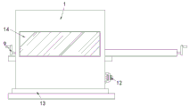
Fig. 1 is a schematic structural diagram of a heat treatment device for machining and forging a tool according to the present invention;
fig. 2 is a schematic view of the overall structure of fig. 1.
In the figure: the device comprises a shell 1, a heating pipe 2, a fixing plate 3, a supporting plate 4, a sliding block 5, a rotating rod 6, a rotating plate 7, a cutter groove 8, a handle 9, a sliding plate 10, a reciprocating screw rod 11, a motor 12, a base 13 and an observation window 14.
Detailed Description
The technical solutions in the embodiments of the present invention will be described clearly and completely with reference to the accompanying drawings in the embodiments of the present invention, and it is obvious that the described embodiments are only some embodiments of the present invention, not all embodiments.
In the description of the present invention, it is to be understood that the terms "upper", "lower", "front", "rear", "left", "right", "top", "bottom", "inner", "outer", and the like indicate orientations or positional relationships based on the orientations or positional relationships shown in the drawings, and are only for convenience of description and simplicity of description, and do not indicate or imply that the device or element being referred to must have a particular orientation, be constructed and operated in a particular orientation, and therefore, should not be construed as limiting the present invention.
Referring to fig. 1-2, a forged heat treatment device of cutter processing, including casing 1 and heating pipe 2, a plurality of heating pipes 2 all from a left side to the right side in proper order fixed the setting in casing 1's inside upper end, logical groove has all been seted up to casing 1's middle part both sides wall, two lead to fixedly between the groove being provided with fixed plate 3, the spout has been seted up to fixed plate 3's upper surface, fixed plate 3's upper surface is provided with backup pad 4, slider 5 and spout sliding connection are passed through at backup pad 4's lower surface middle part, backup pad 4's both sides are inside all to be provided with rotor plate 7 through bull stick 6 rotation, a plurality of sword grooves 8 have all been seted up to two rotor plate 7's upper surface, the bar mouth has been seted up to the lower surface of spout, casing 1's inside lower extreme is provided with the drive mechanism who drives slider 5 reciprocating motion.
Drive mechanism includes reciprocal lead screw 11 and slide 10, reciprocal lead screw 11 sets up in the inside lower extreme of casing 1, the both ends of reciprocal lead screw 11 all rotate with the lateral wall of the casing 1 that corresponds through antifriction bearing and be connected, slide 10 screw thread cup joints in the pole wall of reciprocal lead screw 11, the upper end of slide 10 pass the bar mouth and with the lower fixed surface of slider 5 be connected, the right side of casing 1 is provided with motor 12, motor 12's output and the right-hand member fixed connection of reciprocal lead screw 11.
Both sides wall of slide 10 all offsets with the lateral wall of the bar mouth that corresponds, prevents that slide 10 from taking place to rotate for slide 10 can be stable the slip.
The outside one end of two bull sticks 6 all is fixed and is provided with handle 9, conveniently rotates bull stick 6.
The lower surface of the shell 1 is fixedly provided with a base 13 which stably supports the equipment.
The fixed observation window 14 that is provided with of preceding lateral wall of casing 1 conveniently observes the inside processing clearance of casing 1.
In the utility model, when in use, a plurality of cutters are placed inside the corresponding cutter grooves 8 by a worker, then the power supply of the motor 12 is switched on, the motor 12 drives the reciprocating screw rod 11 to rotate, namely, the sliding plate 10 is driven to move, the sliding plate 10 drives the slider 5 to move, namely, the supporting plate 4 can be driven to move, the supporting plate 4 drives the rotating plate 7 with the plurality of cutters to the inside of the shell 1 to carry out heat treatment, namely, the rotating plate 7 is far away from a heat source to carry out feeding, at the moment, the rotating plate 7 at the other side is pushed out of the shell 1 to carry out feeding, at the moment, the rotating plate 7 at the other side can be moved to the inside of the shell 1 to carry out heat treatment continuously after the heat treatment of the cutters inside the shell 1 is finished, the time waste is reduced, the production efficiency is improved, after the heat treatment of the cutters inside the shell 1 is finished, the sliding plate 10 drives the corresponding rotating plate 7 to move out of the shell 1, the handle 9 that corresponds is rotated this moment, can drive this rotor plate 7 rotatory 180 degrees, can carry out the unloading to the cutter that the thermal treatment ended, and the heat source is all kept away from to the unloading promptly, can prevent that the staff from being scalded.
The above, only be the concrete implementation of the preferred embodiment of the present invention, but the protection scope of the present invention is not limited thereto, and any person skilled in the art is in the technical scope of the present invention, according to the technical solution of the present invention and the utility model, the concept of which is equivalent to replace or change, should be covered within the protection scope of the present invention.
Claims (6)
1. A heat treatment device for machining and forging a cutter comprises a shell (1) and a heating pipe (2), it is characterized in that a plurality of heating pipes (2) are fixedly arranged at the upper end of the interior of the shell (1) from left to right in sequence, two side walls of the middle part of the shell (1) are respectively provided with a through groove, a fixed plate (3) is fixedly arranged between the two through grooves, the upper surface of the fixed plate (3) is provided with a sliding chute, the upper surface of the fixed plate (3) is provided with a supporting plate (4), the middle part of the lower surface of the supporting plate (4) is connected with the sliding groove in a sliding way through a sliding block (5), the inner parts of the two sides of the supporting plate (4) are respectively provided with a rotating plate (7) through a rotating rod (6), the upper surfaces of the two rotating plates (7) are respectively provided with a plurality of cutter grooves (8), the lower surface of the sliding groove is provided with a strip-shaped opening, and the lower end in the shell (1) is provided with a transmission mechanism for driving the sliding block (5) to move in a reciprocating manner.
2. The heat treatment device for machining and forging the cutter according to claim 1, wherein the transmission mechanism comprises a reciprocating screw rod (11) and a sliding plate (10), the reciprocating screw rod (11) is arranged at the lower end of the inside of the shell (1), two ends of the reciprocating screw rod (11) are rotatably connected with the corresponding side wall of the shell (1) through rolling bearings, the sliding plate (10) is in threaded sleeve connection with the rod wall of the reciprocating screw rod (11), the upper end of the sliding plate (10) penetrates through a strip-shaped opening and is fixedly connected with the lower surface of the sliding block (5), a motor (12) is arranged on the right side of the shell (1), and the output end of the motor (12) is fixedly connected with the right end of the reciprocating screw rod (11).
3. A tooling forging heat treatment apparatus according to claim 2, wherein both side walls of the slide plate (10) abut against the side walls of the corresponding strip-shaped mouth.
4. The heat treatment device for tool machining forging according to claim 1, wherein a handle (9) is fixedly arranged at one end of the outer side of each of the two rotating rods (6).
5. The heat treatment device for tool machining forging according to claim 1, characterized in that a base (13) is fixedly provided to a lower surface of the housing (1).
6. The heat treatment apparatus for tooling forging according to claim 1, wherein a viewing window (14) is fixedly provided to a front side wall of the housing (1).
Priority Applications (1)
| Application Number | Priority Date | Filing Date | Title |
|---|---|---|---|
| CN202121340251.6U CN214991736U (en) | 2021-06-17 | 2021-06-17 | Heat treatment device for machining and forging cutter |
Applications Claiming Priority (1)
| Application Number | Priority Date | Filing Date | Title |
|---|---|---|---|
| CN202121340251.6U CN214991736U (en) | 2021-06-17 | 2021-06-17 | Heat treatment device for machining and forging cutter |
Publications (1)
| Publication Number | Publication Date |
|---|---|
| CN214991736U true CN214991736U (en) | 2021-12-03 |
Family
ID=79129131
Family Applications (1)
| Application Number | Title | Priority Date | Filing Date |
|---|---|---|---|
| CN202121340251.6U Expired - Fee Related CN214991736U (en) | 2021-06-17 | 2021-06-17 | Heat treatment device for machining and forging cutter |
Country Status (1)
| Country | Link |
|---|---|
| CN (1) | CN214991736U (en) |
Cited By (1)
| Publication number | Priority date | Publication date | Assignee | Title |
|---|---|---|---|---|
| CN117781695A (en) * | 2024-02-27 | 2024-03-29 | 沈阳中金模具集团有限公司 | Resistance furnace with automatic feeding and discharging structure of die |
-
2021
- 2021-06-17 CN CN202121340251.6U patent/CN214991736U/en not_active Expired - Fee Related
Cited By (2)
| Publication number | Priority date | Publication date | Assignee | Title |
|---|---|---|---|---|
| CN117781695A (en) * | 2024-02-27 | 2024-03-29 | 沈阳中金模具集团有限公司 | Resistance furnace with automatic feeding and discharging structure of die |
| CN117781695B (en) * | 2024-02-27 | 2024-05-07 | 沈阳中金模具集团有限公司 | Resistance furnace with automatic feeding and discharging structure of die |
Similar Documents
| Publication | Publication Date | Title |
|---|---|---|
| CN114669778A (en) | Efficient drilling device for motor production and using method | |
| CN104526214A (en) | Corrugated plate robot | |
| CN206567548U (en) | A kind of propulsion plant processed for bearing chamfer | |
| CN211142111U (en) | Heat treatment device for engine chain wheel | |
| CN215050559U (en) | Cutter processing heat preservation device | |
| CN218469381U (en) | Efficient heat exchanger for lubricating oil refining device | |
| CN217230863U (en) | Heat treatment rapid cooling device for threaded rod | |
| CN211972402U (en) | Machine tool heat treatment device for machining nut | |
| CN215788630U (en) | Steel pipe machining device with sound insulation effect | |
| CN213422659U (en) | Hydraulic engineering is with concrete drilling coring equipment that can cool off fast | |
| CN211360793U (en) | Steel plate edge milling machine | |
| CN211306430U (en) | Building material cutting equipment convenient to use | |
| CN206970670U (en) | A kind of high-precision steel plate rolling after annealing device | |
| CN223558144U (en) | High-efficient medical burnishing machine | |
| CN219747263U (en) | Cooling device in machining process of mechanical parts | |
| CN223300839U (en) | Cold forging warm forging numerical control device for forged piece | |
| CN209736347U (en) | Precision copper piece capillary tube drawing cooling device | |
| CN214937691U (en) | Heat treatment equipment for blade | |
| CN221390906U (en) | Machining platform of steel structure | |
| CN217861071U (en) | Can accomplish chemical reagent box compression fittings of amalgamation in advance automatically | |
| CN217973291U (en) | Metal surface heat treatment device | |
| CN211112129U (en) | Spring heating furnace | |
| CN212551820U (en) | Drilling equipment is used in gear machining | |
| CN220825524U (en) | Cutting machine for processing porous flat tube aluminum alloy for radiator | |
| CN223353564U (en) | Numerical control machine tool for crankshaft |
Legal Events
| Date | Code | Title | Description |
|---|---|---|---|
| GR01 | Patent grant | ||
| GR01 | Patent grant | ||
| CF01 | Termination of patent right due to non-payment of annual fee | ||
| CF01 | Termination of patent right due to non-payment of annual fee |
Granted publication date: 20211203 |