Disclosure of Invention
The utility model aims to solve the technical problem that overcome prior art's defect, provide a membrane material book twines sealing-tape device, it can be automatic at the surperficial winding sticky tape of membrane material book, and production efficiency is high.
In order to solve the technical problem, the technical scheme of the utility model is that: a film roll twines the tape unit, it includes framework, translation shelf, tape roll unwinding mechanism, film roll winding mechanism, translation actuating mechanism and lifting drive mechanism; wherein,
the film roll is supported on the film roll winding mechanism, the adhesive tape roll unwinding mechanism is used for supporting an adhesive tape roll and unwinding the adhesive tape roll, and the sticking surface of the head of the adhesive tape unwound by the adhesive tape roll unwinding mechanism faces upwards;
the translation frame is arranged on the rack in a sliding mode, the lifting driving mechanism is arranged between the translation frame and the adhesive tape roll unwinding mechanism, and the translation driving mechanism is connected with the translation frame to drive the translation frame to translate towards the film material roll so that the head of the adhesive tape is located right below the film material roll;
the lifting driving mechanism is used for driving the adhesive tape roll unwinding mechanism to ascend when the head of the adhesive tape translates to the position right below the film roll so that the head of the adhesive tape can be pasted on the film roll, and the film roll winding mechanism is used for driving the film roll to rotate to wind the adhesive tape when the head of the adhesive tape is pasted on the film roll.
Further provided is a concrete structure of adhesive tape roll unwinding mechanism, adhesive tape roll unwinding mechanism includes:
and the lifting driving mechanism is connected with the unwinding frame.
The unwinding shaft is rotatably supported on the unwinding frame, and the adhesive tape roll is sleeved on the unwinding shaft;
the flat plate is arranged on the unreeling frame and positioned above the unreeling shaft, and the head of the adhesive tape bypasses the flat plate and is paved on the flat plate with the adhesive surface facing upwards.
Further, in order to reduce the unwinding resistance of the adhesive tape, the adhesive tape roll unwinding mechanism further comprises a supporting roller which is rotatably supported on the unwinding frame and is positioned at the side end of the flat plate, and the head of the adhesive tape is paved on the flat plate with the adhesive surface facing upwards after bypassing the supporting roller.
Further, in order to automatically cut off the adhesive tape, the film material winding adhesive tape device further comprises a cutting mechanism which is arranged on the adhesive tape roll unwinding mechanism and is used for cutting off the adhesive tape after the film material roll finishes the adhesive tape winding operation.
There is further provided a concrete structure of a cutting mechanism, the cutting mechanism including:
the screw rod is rotatably supported on the unreeling frame, and the axial direction of the screw rod is parallel to the axial direction of the unreeling shaft;
the nut block is arranged on the unwinding frame in a sliding mode and is in threaded connection with the screw rod;
the cutting groove is formed in the flat plate, and the head of the blade penetrates through the cutting groove from bottom to top;
and the motor is connected with the screw rod to drive the screw rod to rotate.
Further, in order to make the head of the adhesive tape always flatly laid on the flat plate, the adhesive tape roll unwinding mechanism further comprises a pressing roller which is rotatably supported on the unwinding frame and presses the part of the adhesive tape flatly laid on the flat plate.
Further provides a specific structure of rolling mechanism is rolled up to membrane material, membrane material roll-up rolling mechanism includes:
the first support mechanism comprises a rotating motor and a first plug connector, wherein the first plug connector is used for being inserted into one end of a winding shaft of the film material roll and driving the film material roll to rotate when the first plug connector rotates, and the rotating motor is connected with the first plug connector to drive the first plug connector to rotate;
the second supporting mechanism, the second supporting mechanism includes flexible driving piece and the other end that is used for inserting the rolling axle, and so that the rolling axle is around its pivoted second plug connector, flexible driving piece with the second plug connector links to each other and inserts the other end of rolling axle with the drive second plug connector.
Further, in order to prevent the first plug connector from rotating relative to the winding shaft, the part, inserted into the winding shaft, of the first plug connector is of a prism structure, and a polygonal hole matched with the prism structure is formed in one end of the winding shaft.
The translation driving mechanism comprises a translation cylinder, a cylinder body of the translation cylinder is fixed on the rack, and a cylinder rod of the translation cylinder is connected with the translation frame.
The concrete structure of an upgrading driving mechanism is further provided, the hoisting driving mechanism comprises a hoisting cylinder, a cylinder body of the hoisting cylinder is fixed on the translation frame, and a cylinder rod of the hoisting cylinder is connected with the adhesive tape roll unwinding mechanism.
After the technical scheme is adopted, move through translation actuating mechanism drive translation frame for the head of sticky tape is located the membrane material and rolls up under, it goes upward to roll up unwinding mechanism through lift actuating mechanism drive sticky tape, make the head of sticky tape paste the lower extreme at the membrane material, then roll up winding mechanism drive membrane material through the membrane material and roll up the rotation, and unreel through sticky tape pulling sticky tape roll, and then twine the surface at the membrane material book with the sticky tape, accomplish the winding back, cut off the sticky tape, rethread translation actuating mechanism and lift actuating mechanism drive sticky tape roll unwinding mechanism reset, in order to wait for the operation of twining the sticky tape next time, the utility model discloses can twine the sticky tape on the surface that the membrane material was rolled up automatically, play the effect that the fixed membrane material was rolled up, removed the artifical trouble of twining the sticky tape from, improved work efficiency.
Detailed Description
In order that the present invention may be more readily and clearly understood, the following detailed description of the present invention is provided in connection with the accompanying drawings.
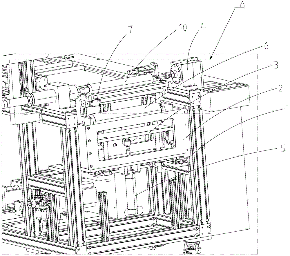
As shown in fig. 1, 2 and 3, a film roll winding device includes a frame 1, a translation frame 2, a tape roll unwinding mechanism 3, a film roll winding mechanism 4, a translation driving mechanism and a lifting driving mechanism; wherein,
the film roll 10 is supported on the film roll winding and unwinding mechanism 4, the adhesive tape roll unwinding mechanism 3 is used for supporting the adhesive tape roll 6 and unwinding the adhesive tape roll 6, and the adhesive surface of the head of the adhesive tape unwound by the adhesive tape roll unwinding mechanism 3 faces upwards;
the translation frame 2 is slidably arranged on the rack 1, the lifting driving mechanism is arranged between the translation frame 2 and the adhesive tape roll unreeling mechanism 3, and the translation driving mechanism is connected with the translation frame 2 to drive the translation frame 2 to translate towards the film roll 10 so that the head part of the adhesive tape is positioned right below the film roll 10;
the lifting driving mechanism is used for driving the adhesive tape roll unwinding mechanism 3 to ascend when the head of the adhesive tape translates to be right below the film material roll 10 so that the head of the adhesive tape is pasted on the film material roll 10, and the film material roll winding mechanism 4 is used for driving the film material roll 10 to rotate to wind the adhesive tape when the head of the adhesive tape is pasted on the film material roll 10.
Specifically, move through translation actuating mechanism drive translation frame 2 for the head of sticky tape is located the membrane material and rolls up under 10, goes upward through lifting drive mechanism drive sticky tape roll unwinding mechanism 3, makes the head of sticky tape paste the lower extreme at membrane material roll 10, then it is rotatory to roll up winding mechanism 4 drive membrane material roll 10 through membrane material, and unreel through sticky tape pulling sticky tape roll 6, and then twine the surface at membrane material roll 10 with the sticky tape, accomplish the winding back, cut off the sticky tape, rethread translation actuating mechanism and lifting drive mechanism drive sticky tape roll unwinding mechanism 3 resets, in order to wait for the operation of twining the sticky tape next time, the utility model discloses can twine the surface at membrane material roll 10 with the sticky tape automatically, play the effect that fixed membrane material rolled 10, removed the trouble of artifical sticky tape of twining from, improved work efficiency.
In this embodiment, the translation driving mechanism includes a translation cylinder, a cylinder body of the translation cylinder is fixed on the frame 1, and a cylinder rod of the translation cylinder is connected with the translation frame 2. The lifting driving mechanism comprises a lifting cylinder 5, a cylinder body of the lifting cylinder 5 is fixed on the translation frame 2, and a cylinder rod of the lifting cylinder 5 is connected with the adhesive tape roll unwinding mechanism 3.
As shown in fig. 1 and 2, the tape roll unwinding mechanism 3 includes:
and the unwinding frame 31, and the lifting driving mechanism is connected with the unwinding frame 31.
An unreeling shaft rotatably supported on the unreeling frame 31, the adhesive tape roll 6 being sleeved on the unreeling shaft;
a flat plate 32, the flat plate 32 is arranged on the unreeling rack 31 and is positioned above the unreeling shaft, and the head of the adhesive tape is wound around the flat plate 32 and is flatly laid on the flat plate 32 with the adhering surface facing upwards.
As shown in fig. 2, in order to reduce the unwinding resistance of the adhesive tape, the tape roll unwinding mechanism 3 further includes a support roller 33 rotatably supported on the unwinding frame 31 and located at the side end of the flat plate 32, and the head of the adhesive tape is laid on the flat plate 32 with its adhesive surface facing upward after passing around the support roller 33.
As shown in fig. 1 and 3, in order to automatically cut the adhesive tape, the roll of film material winding adhesive tape apparatus further includes a cutting mechanism 7 mounted on the roll unwinding mechanism 3 and configured to cut the adhesive tape after the roll of film material 10 completes the tape winding operation.
As shown in fig. 1 and 3, the cutting mechanism 7 includes:
a screw rod 71 rotatably supported on the unreeling frame 31, wherein the axial direction of the screw rod 71 is parallel to the axial direction of the unreeling shaft;
a nut block 72 which is matched on the unreeling frame 31 in a sliding way and is connected with the screw rod 71 in a threaded way;
a blade 73 mounted on the nut block 72, wherein a cutting groove is formed in the flat plate 32, and the head of the blade 73 penetrates through the cutting groove from bottom to top;
and a motor connected with the screw rod 71 to drive the screw rod 71 to rotate.
As shown in fig. 2, in order to make the head of the adhesive tape always lay flat on the flat plate 32, the tape roll unwinding mechanism 3 further includes a pressing roller 34 rotatably supported on the unwinding frame 31 and pressing the portion of the adhesive tape laid on the flat plate 32.
As shown in fig. 1 and 3, the film roll winding mechanism 4 includes:
the film winding device comprises a first supporting mechanism, a second supporting mechanism and a third supporting mechanism, wherein the first supporting mechanism comprises a rotating motor 41 and a first plug connector 42 which is used for being inserted into one end of a winding shaft of the film material roll 10 and driving the film material roll 10 to rotate when the first plug connector 42 rotates, and the rotating motor 41 is connected with the first plug connector 42 to drive the first plug connector 42 to rotate;
and the second supporting mechanism comprises a telescopic driving piece 43 and a second plug piece 44 which is used for inserting the other end of the winding shaft and enabling the winding shaft to rotate around the second plug piece 44, wherein the telescopic driving piece 43 is connected with the second plug piece 44 to drive the second plug piece 44 to insert the other end of the winding shaft.
In particular, the film material winding-up mechanism 4 with the structure can well support the film material roll 10 and facilitate the taking-up and putting-down of the film material roll 10.
As shown in fig. 1 and 3, in order to prevent the first plug 42 from rotating relative to the take-up reel, the portion of the first plug 42 inserted into the take-up reel has a prismatic structure, and a polygonal hole matched with the prismatic structure is arranged at one end of the take-up reel.
The above-mentioned embodiments further explain in detail the technical problems, technical solutions and advantages solved by the present invention, and it should be understood that the above only is a specific embodiment of the present invention, and is not intended to limit the present invention, and any modifications, equivalent substitutions, improvements, etc. made within the spirit and principle of the present invention should be included in the scope of the present invention.
In the description of the present invention, it is to be understood that the terms indicating orientation or positional relationship are based on the orientation or positional relationship shown in the drawings, and are only for convenience of description and simplification of description, and do not indicate or imply that the equipment or elements referred to must have a specific orientation, be constructed and operated in a specific orientation, and thus, should not be construed as limiting the present invention.
In the present invention, unless otherwise expressly stated or limited, the terms "mounted," "connected," and "fixed" are to be construed broadly and may, for example, be fixedly connected, detachably connected, or integrally formed; can be mechanically or electrically connected; either directly or indirectly through intervening media, either internally or in any other relationship. The specific meaning of the above terms in the present invention can be understood according to specific situations by those skilled in the art.
In the description of the present invention, it should be noted that the terms "center", "upper", "lower", "left", "right", "vertical", "horizontal", "inner", "outer", and the like indicate the position or positional relationship based on the position or positional relationship shown in the drawings, or the position or positional relationship which is usually placed when the product of the present invention is used, and are only for convenience of description and simplification of the description, but do not indicate or imply that the device or element referred to must have a specific position, be constructed and operated in a specific orientation, and thus, should not be construed as limiting the present invention. Furthermore, the terms "first," "second," "third," and the like are used solely to distinguish one from another and are not to be construed as indicating or implying relative importance.
Furthermore, the terms "horizontal", "vertical", "overhang" and the like do not imply that the components are required to be absolutely horizontal or overhang, but may be slightly inclined. For example, "horizontal" merely means that the direction is more horizontal than "vertical" and does not mean that the structure must be perfectly horizontal, but may be slightly inclined.
In the present disclosure, unless otherwise expressly stated or limited, the first feature may comprise both the first and second features directly contacting each other, and also may comprise the first and second features not being directly contacting each other but being in contact with each other by means of further features between them. Also, the first feature being above, on or above the second feature includes the first feature being directly above and obliquely above the second feature, or merely means that the first feature is at a higher level than the second feature. A first feature that underlies, and underlies a second feature includes a first feature that is directly under and obliquely under a second feature, or simply means that the first feature is at a lesser level than the second feature.