Automatic cut mouth of a river device
Technical Field
The utility model belongs to the technical field of cut mouth of a river device, concretely relates to automatic cut mouth of a river device.
Background
Plastic parts are common structures in production and life, and are used in many places such as housings of machinery and equipment, housings of household appliances, articles for daily use and the like. Injection molding is a method of molding plastic parts, and is widely used because it can be rapidly produced in large quantities. The injection molding part needs to remove a water gap left in injection molding after injection molding is finished, the injection molding part is taken out of an injection mold through a mechanical arm, and the injection molding part is placed on a platform and cut off through a cutter. The injection molding of the mobile phone back plate and the middle plate is provided with a water gap material, and the water gap is removed when post-processing treatment is needed in the production process.
The prior automatic water gap cutting device has the following problems when in use:
1. the positioning plate of the existing automatic water gap cutting device is inconvenient to adjust when the device is used, so that the device cannot be suitable for plastic parts with different sizes, and the traditional water gap needs manual cutting pliers, and the blade is processed to easily cause the unclean processing of the water gap and cut the product.
2. The existing automatic water gap cutting device is inconvenient for shielding and collecting scattered materials on two sides during cutting, so that the materials fly disorderly.
SUMMERY OF THE UTILITY MODEL
An object of the utility model is to provide an automatic cut mouth of a river device to propose the automatic mouth of a river device of cutting that has now in solving above-mentioned background art in the use, because the current automatic mouth of a river device of cutting is inconvenient when using the locating plate to be adjusted, inconvenient material to both sides scatter shelters from and collects when cutting, thereby influences the problem of the die-cut quality in plastic part mouth of a river.
In order to achieve the above object, the utility model provides a following technical scheme: an automatic water gap cutting device comprises a base, wherein the outer wall of the top of the base is fixedly connected with four supporting columns, the outer walls of the four supporting columns are slidably connected with a push plate, one ends of the supporting columns, far away from the base, are fixedly connected with a mounting plate, the outer wall of the top of the mounting plate is fixedly connected with an air cylinder, one end of the air cylinder is fixedly connected with the outer wall of the top of the push plate, the outer wall of the bottom of the push plate is fixedly connected with a blade, the inner wall of the base is provided with two sliding grooves, the inner walls of the two sliding grooves are both slidably connected with two sliding blocks, the outer walls of the tops of the two sliding blocks are respectively fixedly connected with a first positioning plate and a second positioning plate, the inner wall of the base is provided with a first pull rod in an inserting manner, the outer wall of the first pull rod is sleeved with a spring, and one end of the first pull rod is fixedly connected with a positioning plate, the one end fixedly connected with fixed block that the limiting plate was kept away from to first pull rod, the equal fixedly connected with collecting box of both sides outer wall of base.
Preferably, the outer wall of one side of the collecting box far away from the base is fixedly connected with a baffle, and the outer wall of one side of the baffle far away from the collecting box is fixedly connected with a pull ring.
Preferably, the inner wall of the base is provided with a movable groove, the outer wall of one side, away from the baffle, of the collecting box is fixedly connected with a clamping plate, the outer wall of the bottom of the clamping plate is fixedly connected with a fixed plate, the outer wall of the bottom of the fixed plate is rotatably connected with a rolling wheel, and the outer wall of the rolling wheel is in sliding connection with the inner wall of the movable groove.
Preferably, the outer walls of the first positioning plate and the second positioning plate are provided with positioning holes.
Preferably, a clamping groove is formed in the outer wall of one side of the sliding block, and the outer wall of the limiting plate is clamped with the inner wall of the clamping groove.
Preferably, the inner wall of the second positioning plate is fixedly connected with a second pull rod, and the outer wall of the second pull rod is movably connected with the inner wall of the first positioning plate and penetrates through the first positioning plate.
Compared with the prior art, the beneficial effects of the utility model are that:
1. drive the push pedal up-and-down motion through the cylinder, the up-and-down motion of push pedal drives the blade and carries out die-cut to the plastic part, and this device increases the blade of excision mouth of a river, and after the product shaping, the mouth of a river is accomplished by die-cut tool, reduces artifically, improves the productivity, effectively improves quality stability, has solved traditional mouth of a river and needs artifical with cutting nipper, and blade processing causes the mouth of a river processing unclean easily, cuts the problem of hindering the product.
2. Make its pulling limiting plate to the direction motion of keeping away from the slider through the first pull rod of pulling, make the slider can move about, make the limiting plate bounce-back under the effect of spring through loosening first pull rod, make the limiting plate carry on the slider spacing, avoid its removal, this device is convenient to be adjusted the distance between two locating plates, adjust the distance between first locating plate and the second locating plate through the pulling second pull rod to be applicable to the plastic part of equidimension not, made things convenient for simultaneously fixed to the locating plate.
3. Through the setting of baffle, the plastic part that the subtend both sides were scattered stops, and the plastic part that is stopped falls into the collecting box in, collects the material through the collecting box, through the pulling pull ring, the wheel that rolls slides in the activity inslot to the collecting box is installed and is dismantled to the convenience.
Drawings
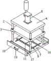
Fig. 1 is a schematic perspective view of the present invention;
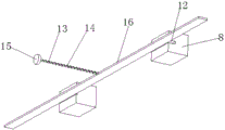
fig. 2 is a schematic perspective view of the present invention;
FIG. 3 is a schematic structural view of the present invention;
fig. 4 is a schematic structural diagram of the present invention.
In the figure: 1. a base; 2. a support pillar; 3. pushing the plate; 4. mounting a plate; 5. a cylinder; 6. a blade; 7. a chute; 8. a slider; 9. a first positioning plate; 10. a second positioning plate; 11. positioning holes; 12. a clamping groove; 13. a first pull rod; 14. a spring; 15. a fixed block; 16. a limiting plate; 17. a collection box; 18. a baffle plate; 19. a pull ring; 20. a clamping and connecting plate; 21. a fixing plate; 22. a rolling wheel; 23. a second pull rod.
Detailed Description
The technical solutions in the embodiments of the present invention will be described clearly and completely with reference to the accompanying drawings in the embodiments of the present invention, and it is obvious that the described embodiments are only some embodiments of the present invention, not all embodiments. Based on the embodiments in the present invention, all other embodiments obtained by a person skilled in the art without creative work belong to the protection scope of the present invention.
Referring to fig. 1-4, the present invention provides a technical solution: an automatic water gap cutting device comprises a base 1, wherein the outer wall of the top of the base 1 is fixedly connected with four supporting columns 2, the outer walls of the four supporting columns 2 are slidably connected with a push plate 3, one ends of the supporting columns 2 far away from the base 1 are fixedly connected with a mounting plate 4, the outer wall of the top of the mounting plate 4 is fixedly connected with an air cylinder 5, one end of the air cylinder 5 is fixedly connected with the outer wall of the top of the push plate 3, the outer wall of the bottom of the push plate 3 is fixedly connected with a blade 6, the inner wall of the base 1 is provided with two sliding grooves 7, the inner walls of the two sliding grooves 7 are both slidably connected with two sliding blocks 8, the outer walls of the top of the two sliding blocks 8 are respectively fixedly connected with a first positioning plate 9 and a second positioning plate 10, the inner wall of the base 1 is provided with a first pull rod 13 in an inserting manner, the outer wall of the first pull rod 13 is sleeved with a spring 14, and one end of the first pull rod 13 is fixedly connected with a limiting plate 16, one end of the first pull rod 13 far away from the limiting plate 16 is fixedly connected with a fixing block 15, and the outer walls of the two sides of the base 1 are fixedly connected with a collecting box 17.
In this embodiment, drive 3 up-and-down motion of push pedal through cylinder 5, the up-and-down motion of push pedal 3 drives blade 6 and punches to the plastic part, this device increases the blade 6 of excision mouth of a river, after the product shaping, the mouth of a river is accomplished by die-cut tool, reduce the manual work, improve the productivity, effectively improve the stability of quality, make its pulling limiting plate 16 move to the direction of keeping away from slider 8 through pulling first pull rod 13, make slider 8 can move about, adjust the distance between first locating plate 9 and the second locating plate 10 through pulling second pull rod 23, thereby be applicable to the plastic part of equidimension not, make limiting plate 16 bounce-back under spring 14's effect through loosening first pull rod 13, make limiting plate 16 carry out spacingly with slider 8, avoid its removal.
Specifically, the outer wall of one side of the collecting box 17 far away from the base 1 is fixedly connected with a baffle 18, and the outer wall of one side of the baffle 18 far away from the collecting box 17 is fixedly connected with a pull ring 19.
In this embodiment, through the setting of baffle 18, the plastic part that the opposite direction both sides were scattered stops, and the plastic part that is stopped falls into collecting box 17 in, collects the material through collecting box 17, conveniently stimulates collecting box 17 through pulling pull ring 19.
Specifically, the movable groove has been seted up to the inner wall of base 1, and collecting box 17 keeps away from one side outer wall fixedly connected with joint board 20 of baffle 18, and the bottom outer wall fixedly connected with fixed plate 21 of joint board 20, the bottom outer wall of fixed plate 21 rotate and are connected with the wheel 22 that rolls, the outer wall of the wheel 22 that rolls and the inner wall sliding connection in movable groove.
In this embodiment, the connection between the collecting box 17 and the base 1 is facilitated by the arrangement of the clamping plate 20 and the movable groove, and the rolling wheels 22 slide in the movable groove, so that the collecting box 17 is convenient to mount and dismount.
Specifically, the outer walls of the first positioning plate 9 and the second positioning plate 10 are both provided with positioning holes 11.
In this embodiment, the plastic part is conveniently located through the setting of first locating plate 9, second locating plate 10 and locating hole 11, and is conveniently die-cut to the plastic part.
Specifically, the outer wall of one side of the sliding block 8 is provided with a clamping groove 12, and the outer wall of the limiting plate 16 is clamped with the inner wall of the clamping groove 12.
In this embodiment, the sliding block 8 is conveniently fixed and limited by the clamping groove 12 and the limiting plate 16.
Specifically, the inner wall of the second positioning plate 10 is fixedly connected with a second pull rod 23, and the outer wall of the second pull rod 23 is movably connected with the inner wall of the first positioning plate 9 and penetrates through the first positioning plate 9.
In the present embodiment, the distance between the first positioning plate 9 and the second positioning plate 10 is conveniently adjusted by the arrangement of the second pull rod 23.
The utility model discloses a theory of operation and use flow: when the plastic part punching device is used, the push plate 3 is driven to move up and down through the air cylinder 5, the blade 6 is driven to punch a plastic part through the up-and-down movement of the push plate 3, the blade 6 for cutting off a water gap is additionally arranged, after a product is formed, the water gap is finished by a punching jig, the labor is reduced, the productivity is improved, the quality stability is effectively improved, the first pull rod 13 is pulled to pull the limiting plate 16 to move towards the direction away from the slide block 8, the slide block 8 can move, the second pull rod 23 is pulled to adjust the distance between the first positioning plate 9 and the second positioning plate 10, so that the plastic part punching device is suitable for plastic parts with different sizes, the limiting plate 16 rebounds under the action of the spring 14 by loosening the first pull rod 13, the slide block 8 is limited by the limiting plate 16, and the movement of the slide block is avoided; through the setting of baffle 18, the plastic part that the opposite direction both sides were scattered stops, and the plastic part that is stopped falls into collecting box 17 in, collects the material through collecting box 17, through pulling pull ring 19, rolls wheel 22 and slides in the activity inslot to conveniently install collecting box 17 and dismantle.
Although embodiments of the present invention have been shown and described, it will be appreciated by those skilled in the art that changes, modifications, substitutions and alterations can be made in these embodiments without departing from the principles and spirit of the invention, the scope of which is defined in the appended claims and their equivalents.