Material sheet positioning mechanism of forming die
Technical Field
The utility model relates to a forming die tablet positioning mechanism.
Background
With the continuous improvement of the life quality of people, the automobile keeping quantity is increased year by year, and the style and the appearance of the automobile are also continuously optimized and more attractive. Thus, in the manufacturing process of automobiles, L-shaped, V-shaped, U-shaped and other panel structures with large-profile fluctuation are used in large quantity. These types of panel structures are manufactured by first positioning a blank onto a lower die having a contoured surface that is contoured or curved when mated with an upper die. In the process, the blank is bent, sagged and inclined downwards at the position of the bending surface or the bending surface of the lower die under the influence of the dead weight, so that the blank state is uncertain, the quality of a product obtained by profiling processing is unstable, and the rejection rate is high.
SUMMERY OF THE UTILITY MODEL
An object of the utility model is to provide a forming die tablet positioning mechanism for it is unstable to solve the great panel structure processingquality of current profile undulation, problem that the rejection rate is high.
The utility model discloses a forming die tablet positioning mechanism includes:
the fixed base is used for being fixedly connected to the lower side mold;
the positioning component is arranged on the fixed base;
the positioning member includes:
the positioning vertical plate is provided with a positioning arc surface extending up and down, the profile curve of the positioning arc surface is matched with the motion track of the edge of the material sheet in the downward pressing and bending process, and the positioning arc surface limits the material sheet in the horizontal direction by stopping the edge of the material sheet;
the rotary bearing piece is rotatably arranged on the positioning vertical plate around a horizontal axis, a bearing section and a limiting section are respectively arranged on two sides of the rotating axis, and the gravity center of the rotary bearing piece is positioned on the limiting section;
the lower limiting structure is fixedly arranged on the positioning vertical plate or the fixed base and is used for abutting against the limiting section to limit the downward rotation position of the limiting section;
when the limiting section is supported and limited by the lower limiting structure, the supporting section extends out of the positioning cambered surface and is used for supporting the pressed material sheet;
when the rotary supporting piece rotates to the position that the supporting section is downward and is just parallel to the positioning cambered surface or just swings over the positioning cambered surface, the gravity center of the rotary supporting piece is positioned on one side of the rotary axis, which is close to the limiting section.
The utility model discloses a forming die tablet positioning mechanism has locating part, the rotatory bearing piece of rotation installation is under natural state on its location riser, receive self action of gravity to keep the state that contacts in spacing section and lower limit structure, the bearing section stretches out from location cambered surface this moment, and can support the tablet, avoid the position that corresponds to downside mould camber or curved surface of tablet to hang down, reliable location has been carried out to the tablet, guarantee the stable unanimity of tablet state before the shaping, and then guarantee panel structure's shaping quality after the shaping, the yield is improved, and the production cost is reduced. When the material sheet is pressed down by the upper die, the rotary bearing piece automatically overturns due to the pressure of the bearing section, and after the forming is completed, the rotary bearing piece automatically rotates and resets under the action of self gravity, so that the use is more convenient.
Furthermore, the rotary supporting piece is of a rectangular block structure, and when the limiting section is supported and limited by the lower limiting structure, the rotary supporting piece extends horizontally and supports the material sheet through the upper side face of the supporting section. The rotary bearing piece with the structure is simple in structure and convenient to manufacture, and the material sheet is supported by the horizontal plane on the upper side, so that the positioning and supporting are accurate.
Furthermore, the lower limit structure is preferably a lower limit pin fixed on the positioning vertical plate, so that the structure is simple.
Furthermore, the forming die material sheet positioning mechanism further comprises an upper limiting structure, the upper limiting structure is fixed on the positioning vertical plate or the fixing base and used for limiting the limiting stop of the limiting section so as to limit the upward rotating position of the limiting section, and when the limiting section is stopped by the upper limiting structure, the supporting section just rotates to be flush with the positioning arc surface or just rotates over the positioning arc surface. Through setting up limit structure, can reliably avoid rotatory excessive position of rotatory bearing piece, guarantee the stability in the working process.
Preferably, the upper limit structure is an upper limit pin fixed on the positioning vertical plate, so that the structure is simple.
In addition, the number of the positioning parts is two, the planes of the positioning vertical plates of the two positioning parts are intersected, and the positioning cambered surfaces of the two positioning parts face different directions. Therefore, the two material sheets can be supported and positioned simultaneously through one positioning mechanism, the double-station forming die is suitable for forming dies, and the manufacturing efficiency is improved.
Specifically, an L-shaped vertical plate is arranged on the fixed base, and two sides of the L-shaped vertical plate respectively form positioning vertical plates of the two positioning parts. The structure makes the positioning vertical plates of the two positioning parts in an integrated structure, and has higher structural strength and more compact structure.
Preferably, the rotary supporting pieces of the two positioning parts are respectively positioned on the outer side plate surfaces of two sides of the L-shaped vertical plate. This facilitates assembly.
In addition, unable adjustment base includes horizontal bottom plate, and L shape riser perpendicular to horizontal bottom plate arranges, is equipped with the strengthening rib between the edge of horizontal bottom plate and L shape riser. The structural strength of the whole positioning mechanism is further improved.
Drawings
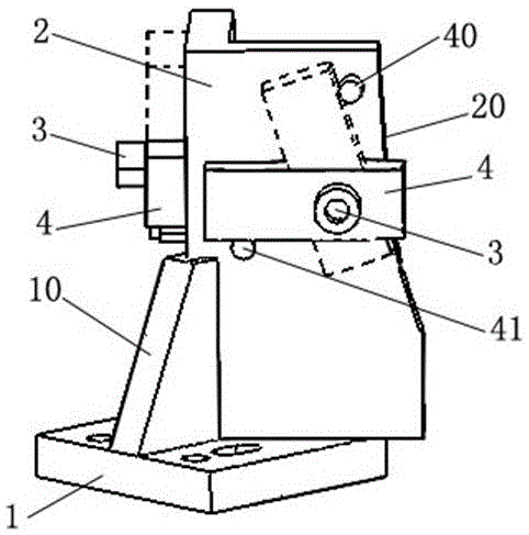
Fig. 1 is a schematic structural view of a first embodiment of a sheet positioning mechanism for a forming die according to the present invention (showing a state where a rotary support is rotated to two extreme positions).
In the figure: 1. a horizontal floor; 10. reinforcing ribs; 2. an L-shaped vertical plate; 20. positioning the arc surface; 3. rotating the pin shaft; 4. rotating the support member; 40. an upper limit pin; 41. and a lower limit pin.
Detailed Description
In order to make the objects, technical solutions and advantages of the present invention more clearly understood, the present invention is further described in detail below with reference to the accompanying drawings and embodiments. It should be understood that the specific embodiments described herein are for purposes of illustration only and are not intended to limit the invention, i.e., the described embodiments are only some, but not all embodiments of the invention. The components of embodiments of the present invention, as generally described and illustrated in the figures herein, may be arranged and designed in a wide variety of different configurations.
Thus, the following detailed description of the embodiments of the present invention, presented in the accompanying drawings, is not intended to limit the scope of the invention, as claimed, but is merely representative of selected embodiments of the invention. Based on the embodiment of the present invention, all other embodiments obtained by the person skilled in the art without creative work belong to the protection scope of the present invention.
It is noted that relational terms such as "first" and "second," and the like, may be used solely to distinguish one entity or action from another entity or action without necessarily requiring or implying any actual such relationship or order between such entities or actions. Also, the terms "comprises," "comprising," or any other variation thereof, are intended to cover a non-exclusive inclusion, such that a process, method, article, or apparatus that comprises a list of elements does not include only those elements but may include other elements not expressly listed or inherent to such process, method, article, or apparatus. Without further limitation, an element defined by the phrase "comprising an … …" does not exclude the presence of other identical elements in a process, method, article, or apparatus that comprises the element.
The features and properties of the present invention are described in further detail below with reference to examples.
The utility model discloses a forming die tablet positioning mechanism's embodiment one:
as shown in fig. 1, the sheet positioning mechanism of the forming die of the present embodiment includes a fixed base and a positioning member fixedly disposed on the fixed base.
The fixed base specifically includes horizontal bottom plate 1, and the locating part includes location riser and rotates and install rotatory supporting piece 4 on the face of location riser. Wherein, the locating component has two in this embodiment, fixedly connected with L shape riser 2 on the horizontal base plate 1, and the both sides of L shape riser 2 constitute two locating component's locating riser respectively, and the rotatory supporting member 4 of two locating component is located on the outside face on the both sides of L shape riser 2 respectively. A reinforcing rib 10 is further arranged between the edges of the horizontal bottom plate 1 and the L-shaped vertical plate 2 to improve the structural strength of the L-shaped vertical plate 2.
The vertical side surfaces of two sides of the L-shaped vertical plate 2 are provided with cambered surface sections extending from top to bottom, and the cambered surface sections form a positioning cambered surface. The location cambered surface section satisfies certain requirement, and the tablet is when being pushed down by the upside mould and bending promptly, and the edge of tablet swings thereupon, and the profile curve of this location cambered surface matches with the swing route at tablet edge, so, when the tablet is pushed down by the upside mould and the bending down swing, the location cambered surface can paste with the edge of tablet all the time to carry out spacing on the horizontal direction to the tablet in the whole shaping process that pushes down at the tablet.
The rotary supporting piece 4 is rotatably installed on the positioning vertical plate through a rotary pin shaft 3 horizontally penetrating and installed on the positioning vertical plate, and the rotary pin shaft 3 specifically comprises a bolt penetrating and installed on the positioning vertical plate and a nut screwed at the penetrating end of the bolt. The whole rotary supporting piece 4 is of a rectangular block structure, and the length of one side of the rotary pin shaft 3 is larger than that of the other side. Wherein, the section of the rotary supporting piece 4 which is at one side of the rotary pin shaft 3 and has shorter length is a supporting section, and the section of the rotary supporting piece 4 which is at the other side of the rotary pin shaft 3 and has longer length is a limiting section, so that the gravity center of the rotary supporting piece 4 is positioned on the limiting section.
An upper limit pin 40 and a lower limit pin 41 are further fixed on the positioning vertical plate of each positioning part, the upper limit pin and the lower limit pin are arranged around the rotating pin shaft 3, and the rotating range of the rotating support 4 is limited in the process that the rotating support 4 rotates around the rotating pin shaft 3.
Wherein, the position that lower limit pin 41 is located satisfies: when the rotary bearing piece 4 rotates to be stopped and limited by the lower limiting piece 41, the rotary bearing piece 4 is in a horizontal state, and the bearing section extends outwards from the positioning cambered surface; the upper stopper 40 is located at a position satisfying: when the rotary supporting piece 4 rotates to be stopped and limited by the upper limiting piece 40, the supporting section of the rotary supporting piece 4 is flush with the positioning arc surface or just rotates over the positioning arc surface, and the center of the rotary supporting piece 4 is positioned at one side of the rotary pin shaft 3, which is back to the positioning arc surface.
Install on forming die's downside mould during the use of forming die tablet positioning mechanism of this embodiment, and be in the position of sinking of the curved surface or the undulation face that is close to downside mould, when the tablet was placed on the shaping face of downside mould, positioning mechanism's bearing section can bear the border position of tablet, and then guarantee that the tablet is in the horizontality, the upside mould is pushed down behind the tablet until before beginning to take shape, the tablet all keeps the horizontality, the state is reliable and stable, can not the drunkenness, then suppress and take shape, the product shaping after the state is stable, the uniformity is good, the yield is high. After the molding is finished, the upper side die returns, the rotary supporting piece rotates to the initial state under the action of self gravity, and the next compression is waited.
The utility model discloses a forming die tablet positioning mechanism is not limited to the embodiment that has introduced above only, still provides below based on the utility model discloses an other deformation embodiments of design concept.
For example, in other embodiments, different from the above-described embodiments, the rotary supporting member may have other shapes, such as an arc-shaped strip, an L-shaped block, or a D-shaped block, and the supporting surface of the limiting section for supporting the material sheet may also have a curved surface or an inclined surface, which is further adaptively adjusted according to actual needs; or, the upper and lower limit structures can be both fixedly arranged on the fixed base and are of a bracket structure; or only the lower limit structure can be arranged, the upper limit structure is omitted, and the gravity center position of the rotary supporting piece is designed to ensure that the rotary supporting piece cannot rotate to be over-positioned; alternatively, only one positioning component can be arranged on the fixed base; or the two positioning parts arranged on the fixed base are mutually independently arranged, and the two positioning parts can be arranged on the fixed base in parallel according to different structural forms of the double-cavity die.
The above description is only for the preferred embodiment of the present invention, and the present invention is not limited thereto, the protection scope of the present invention is defined by the claims, and all structural changes equivalent to the contents of the description and drawings of the present invention should be included in the protection scope of the present invention.