CN214926548U - Plastic toy mould convenient to disassemble - Google Patents
Plastic toy mould convenient to disassemble Download PDFInfo
- Publication number
- CN214926548U CN214926548U CN202023024344.6U CN202023024344U CN214926548U CN 214926548 U CN214926548 U CN 214926548U CN 202023024344 U CN202023024344 U CN 202023024344U CN 214926548 U CN214926548 U CN 214926548U
- Authority
- CN
- China
- Prior art keywords
- die holder
- fixing device
- fixedly connected
- plastic toy
- groove
- Prior art date
- Legal status (The legal status is an assumption and is not a legal conclusion. Google has not performed a legal analysis and makes no representation as to the accuracy of the status listed.)
- Expired - Fee Related
Links
- 229920003023 plastic Polymers 0.000 title claims abstract description 35
- 239000004033 plastic Substances 0.000 title claims abstract description 35
- 230000003139 buffering effect Effects 0.000 claims abstract description 8
- 230000000694 effects Effects 0.000 claims description 17
- 238000010030 laminating Methods 0.000 claims description 4
- 238000001746 injection moulding Methods 0.000 abstract description 7
- 238000012797 qualification Methods 0.000 abstract description 3
- 238000000465 moulding Methods 0.000 description 7
- 238000010586 diagram Methods 0.000 description 2
- 238000000034 method Methods 0.000 description 2
- 238000010137 moulding (plastic) Methods 0.000 description 2
- 239000000758 substrate Substances 0.000 description 2
- 230000009286 beneficial effect Effects 0.000 description 1
- 238000000748 compression moulding Methods 0.000 description 1
- 230000007547 defect Effects 0.000 description 1
- 238000001125 extrusion Methods 0.000 description 1
- 238000005187 foaming Methods 0.000 description 1
- 238000010102 injection blow moulding Methods 0.000 description 1
- 230000007774 longterm Effects 0.000 description 1
- 238000004519 manufacturing process Methods 0.000 description 1
- 238000012986 modification Methods 0.000 description 1
- 230000004048 modification Effects 0.000 description 1
- 238000003672 processing method Methods 0.000 description 1
- 239000000243 solution Substances 0.000 description 1
Images


Landscapes
- Toys (AREA)
Abstract
The utility model discloses a convenient-to-disassemble plastic toy mould, which comprises a lower mould fixing device, wherein the upper end of the lower mould fixing device is detachably connected with a lower mould seat structure, the upper end of the lower mould seat structure is laminated with an upper mould seat structure, the upper end of the lower mould fixing device is provided with an upper mould fixing device which plays a role in fixing the upper mould seat structure, and the inner part of the upper mould seat structure is fixedly connected with a buffer structure which plays a role in buffering protection; the utility model discloses in, can be very convenient through rotating the knob to its upper die base structure fixed, can be well fixed to the lower bolster structure through the annular cover, in long-time injection molding work, can dismantle lower bolster structure and upper die base structure, be convenient for clear up its inside to and change lower bolster structure and upper die base structure, guaranteed injection moulding product's qualification rate, and convenient the dismantlement, simple to use.
Description
Technical Field
The utility model relates to a mould processing field especially relates to a plastics toy mould convenient to dismantle.
Background
The plastic mold is a combined plastic mold for compression molding, extrusion molding, injection molding, blow molding and low-foaming molding, and mainly comprises a female mold with a variable cavity and composed of a female mold combined substrate, a female mold component and a female mold combined clamping plate, and a male mold with a variable core and composed of a male mold combined substrate, a male mold component, a male mold combined clamping plate, a cavity cut-off component and a side cut-off combined plate. And the coordination change of the male die, the female die and the auxiliary forming system of the die. Can process series plastic parts with different shapes and sizes. The plastic processing industry is associated with plastic molding machines that impart tools of complete configuration and precise dimensions to plastic articles. Because of the variety and processing method of plastic, and the structure of plastic molding machines and plastic products are various, the variety and structure of plastic molds are also various.
There are the following problems:
the existing mold for the plastic toy is inconvenient to clean and influence the injection molding quality because some sundries can be doped in the mold in the long-term injection molding process, and the mold is inconvenient to disassemble and replace.
SUMMERY OF THE UTILITY MODEL
The utility model aims at solving the defects existing in the prior art and providing a plastic toy mould convenient to disassemble.
In order to achieve the above purpose, the utility model adopts the following technical scheme: the utility model provides a plastics toy mould convenient to dismantle, includes lower mould fixing device, lower mould fixing device's upper end can be dismantled and be connected with the die holder structure, the laminating of the upper end of die holder structure has the upper die base structure, lower mould fixing device's upper end is provided with the last mould fixing device who plays fixed upper die base structure effect, the inside fixedly connected with of upper die base structure plays the buffer structure of buffering protection effect.
Preferably, the lower die fixing device comprises a workbench and an annular sleeve, the upper end of the workbench is fixedly connected to the bottom end of the annular sleeve, and the workbench and the annular sleeve are rectangular; the lower die base structure is fixed by the lower die fixing device and can be detached, the workbench is used for supporting equipment, and the annular sleeve is used for fixing the lower die base structure.
Preferably, the upper die fixing device comprises a supporting seat, a fixing plate, a side plate, a clamping block and a knob, wherein the bottom end of the supporting seat is fixedly connected to the upper end of the fixing plate, the upper end of the side plate is fixedly connected to the bottom end of the supporting seat, one end of the clamping block is slidably connected to the inside of the fixing plate, and one end of the knob is fixedly connected to the outer side of the fixing plate; the fixing effect on the upper die base structure is achieved through the upper die fixing device, the supporting seat, the fixing plate and the side plates are used for bearing the upper die base structure, and the clamping blocks of the upper die base structure are fixed by rotating the knob.
Preferably, the lower die base structure comprises a lower die base, a die cavity, a vent groove, a vent hole and a guide post groove, the bottom end of the lower die base is detachably connected to the upper end of the annular sleeve, the bottom end of the die cavity is fixedly connected to the inside of the lower die fixing device, the vent groove is arranged at one end of the lower die base, the vent hole is arranged at one end of the die cavity, and the guide post groove is arranged on the surface of the lower die base; play the effect of the toy of moulding plastics through the die holder structure, wherein the die holder is used for supporting the die cavity, and the die cavity is used for the toy setting, and the air channel plays the inside gaseous effect of discharge with the air vent when moulding plastics, prevents that the surface of foundry goods from having bubble or sunken possibility, and the knob plays the effect of connecting the guide pillar.
Preferably, the upper die base structure comprises an upper die base, a guide pillar, a clamping groove and a lifting plate, the bottom end of the upper die base is fixedly connected to the upper end of the guide pillar, the bottom end of the guide pillar is fixedly connected to the inner part of the guide pillar groove, the clamping groove is arranged at one end of the upper die base, and two ends of the lifting plate are slidably connected to the inner side of the clamping groove; play the effect of the toy of moulding plastics through the upper die base structure, wherein the guide pillar slides in the inside in guide pillar groove, makes its upper die base laminating in the upper end of die cavity, accomplishes the work of moulding plastics, and the inside joint of draw-in groove accomplishes the fixed to the upper die base in the one end of fixture block, and the lifter plate plays the effect that drives the upper die base and descend.
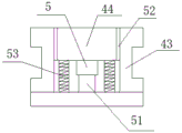
Preferably, the buffer structure comprises a lifting column, a sliding block and a buffer spring, the upper end of the lifting column is fixedly connected to the bottom end of the lifting plate, one end of the sliding block is fixedly connected to two sides of the lifting plate, and the bottom end of the buffer spring is fixedly connected to the upper end of the upper die holder; play the buffering effect when the mould combines through buffer structure and be used for protecting the mould, wherein slider and buffer spring are used for producing the sliding effect, and the effect of buffering is played to the lift post.
Compared with the prior art, the beneficial effects of the utility model are that:
compare current mould for plastics toy, on its original basis, can be very convenient fix its die holder structure through rotating the knob, can be well fixed to the die holder structure through the annular sheath, in long-time injection molding work, can dismantle die holder structure and last die holder structure, be convenient for clear up its inside to and change die holder structure and last die holder structure, guaranteed injection moulding product's qualification rate, and convenient the dismantlement, simple to use.
Drawings
FIG. 1 is a diagram of the overall effect of a plastic toy mold easy to disassemble according to the present invention;
FIG. 2 is a structural view of an upper mold fixing device of a plastic toy mold convenient for disassembly according to the present invention;
FIG. 3 is a lower mold base structure view of a plastic toy mold easy to disassemble according to the present invention;
FIG. 4 is a structural view of an upper mold base of a plastic toy mold convenient for disassembly, which is provided by the utility model;
fig. 5 is a buffering structure diagram of the plastic toy mold convenient to disassemble.
Illustration of the drawings:
1. a lower die fixing device; 2. an upper die fixing device; 3. a lower die holder structure; 4. an upper die base structure; 5. A buffer structure; 11. a work table; 12. an annular sleeve; 21. a supporting seat; 22. a fixing plate; 23. a side plate; 24. a clamping block; 25. a knob; 31. a lower die holder; 32. a mold cavity; 33. a vent channel; 34. a vent hole; 35. a guide post groove; 41. an upper die holder; 42. a guide post; 43. a card slot; 44. a lifting plate; 51. a lifting column; 52. a slider; 53. a buffer spring.
Detailed Description
The technical solutions in the embodiments of the present invention will be described clearly and completely with reference to the accompanying drawings in the embodiments of the present invention, and it is obvious that the described embodiments are only some embodiments of the present invention, not all embodiments. Based on the embodiments in the present invention, all other embodiments obtained by a person skilled in the art without creative work belong to the protection scope of the present invention.
In the description of the present invention, it should be noted that the terms "center", "upper", "lower", "left", "right", "vertical", "horizontal", "inner", "outer", and the like indicate orientations or positional relationships based on the orientations or positional relationships shown in the drawings, and are only for convenience of description and simplification of description, but do not indicate or imply that the device or element referred to must have a specific orientation, be constructed and operated in a specific orientation, and thus, should not be construed as limiting the present invention; the terms "first," "second," and "third" are used for descriptive purposes only and are not to be construed as indicating or implying relative importance, and furthermore, unless otherwise explicitly stated or limited, the terms "mounted," "connected," and "connected" are to be construed broadly and may be, for example, fixedly connected, detachably connected, or integrally connected; can be mechanically or electrically connected; they may be connected directly or indirectly through intervening media, or they may be interconnected between two elements. The specific meaning of the above terms in the present invention can be understood in specific cases to those skilled in the art.
Referring to fig. 1-5, the present invention provides an embodiment: a plastics toy mould convenient to dismantle includes lower mould fixing device 1, its characterized in that: the upper end of lower mould fixing device 1 can be dismantled and be connected with die holder structure 3, and die holder structure 3's upper end laminating has upper die base structure 4, and lower mould fixing device 1's upper end is provided with the last mould fixing device 2 that plays 4 effects of fixed upper die base structure, and the inside fixedly connected with of upper die base structure 4 plays buffer structure 5 of buffering protection effect.
The lower die fixing device 1 comprises a workbench 11 and an annular sleeve 12, the upper end of the workbench 11 is fixedly connected to the bottom end of the annular sleeve 12, and the workbench 11 and the annular sleeve 12 are rectangular; the upper die fixing device 2 comprises a supporting seat 21, a fixing plate 22, a side plate 23, a clamping block 24 and a knob 25, wherein the bottom end of the supporting seat 21 is fixedly connected to the upper end of the fixing plate 22, the upper end of the side plate 23 is fixedly connected to the bottom end of the supporting seat 21, one end of the clamping block 24 is slidably connected to the inside of the fixing plate 22, and one end of the knob 25 is fixedly connected to the outer side of the fixing plate 22; the lower die base structure 3 comprises a lower die base 31, a die cavity 32, a vent groove 33, a vent hole 34 and a guide post groove 35, the bottom end of the lower die base 31 is detachably connected to the upper end of the annular sleeve 12, the bottom end of the die cavity 32 is fixedly connected to the inside of the lower die fixing device 1, the vent groove 33 is arranged at one end of the lower die base 31, the vent hole 34 is arranged at one end of the die cavity 32, and the guide post groove 35 is arranged on the surface of the lower die base 31; the upper die holder structure 4 comprises an upper die holder 41, a guide post 42, a clamping groove 43 and a lifting plate 44, wherein the bottom end of the upper die holder 41 is fixedly connected to the upper end of the guide post 42, the bottom end of the guide post 42 is fixedly connected inside the guide post groove 35, the clamping groove 43 is arranged at one end of the upper die holder 41, and two ends of the lifting plate 44 are slidably connected to the inner side of the clamping groove 43; the buffer structure 5 comprises a lifting column 51, a sliding block 52 and a buffer spring 53, wherein the upper end of the lifting column 51 is fixedly connected to the bottom end of the lifting plate 44, one end of the sliding block 52 is fixedly connected to two sides of the lifting plate 44, and the bottom end of the buffer spring 53 is fixedly connected to the upper end of the upper die holder 41.
Specifically, the method comprises the following steps: the upper end of the lifting plate 44 of the mold structure is driven by the lifting structure to move the upper mold base 41 downward.
And (3) description of a work flow: make fixture block 24 toward the outward movement through rotating, place upper die base structure 4 in the bottom of supporting seat 21, rotate knob 25 and make fixture block 24 block in the inside of draw-in groove 43, accomplish the fixed to upper die base structure 4, place lower die base structure 3 in the inside of annular cover 12, make its lower die base structure 3 fixed, the starting equipment, it descends to drive lifter plate 44 through outside elevation structure, make its upper die base 41 laminate in the upper end of die cavity 32, under the sliding effect of slider 52, play the effect of buffering through lift post 51 and buffer spring 53, inside atmospheric pressure of moulding plastics is discharged from air vent 34, the stability of its toy processing has been guaranteed, the qualification rate, accomplish the production of moulding plastics of plastic toy.
Finally, it should be noted that: although the present invention has been described in detail with reference to the foregoing embodiments, it will be apparent to those skilled in the art that modifications and variations can be made in the embodiments or in part of the technical features of the embodiments without departing from the spirit and the principles of the present invention.
Claims (6)
1. A plastic toy mould convenient to dismantle comprises a lower mould fixing device (1) and is characterized in that: the upper end of lower mould fixing device (1) can be dismantled and be connected with die holder structure (3), the upper end laminating of die holder structure (3) has last die holder structure (4), the upper end of lower mould fixing device (1) is provided with last die fixing device (2) that play fixed upper die holder structure (4) effect, the inside fixedly connected with of upper die holder structure (4) plays buffer structure (5) of buffering protection effect.
2. A readily removable plastic toy mold as recited in claim 1, wherein: lower mould fixing device (1) includes workstation (11) and annular cover (12), the upper end fixed connection of workstation (11) is in the bottom of annular cover (12), the shape of workstation (11) and annular cover (12) is the rectangle.
3. A readily removable plastic toy mold as recited in claim 1, wherein: go up mould fixing device (2) including supporting seat (21), fixed plate (22), curb plate (23), fixture block (24) and knob (25), the bottom fixed connection of supporting seat (21) is in the upper end of fixed plate (22), the upper end fixed connection of curb plate (23) is in the bottom of supporting seat (21), the one end sliding connection of fixture block (24) is in the inside of fixed plate (22), the one end fixed connection of knob (25) is in the outside of fixed plate (22).
4. A readily removable plastic toy mold as recited in claim 1, wherein: the lower die holder structure (3) comprises a lower die holder (31), a die cavity (32), a vent groove (33), a vent hole (34) and a guide post groove (35), the bottom end of the lower die holder (31) is detachably connected to the upper end of the annular sleeve (12), the bottom end of the die cavity (32) is fixedly connected to the inside of the lower die fixing device (1), the vent groove (33) is arranged at one end of the lower die holder (31), the vent hole (34) is arranged at one end of the die cavity (32), and the guide post groove (35) is arranged on the surface of the lower die holder (31).
5. A readily removable plastic toy mold as recited in claim 1, wherein: the upper die holder structure (4) comprises an upper die holder (41), a guide pillar (42), a clamping groove (43) and a lifting plate (44), the bottom end of the upper die holder (41) is fixedly connected to the upper end of the guide pillar (42), the bottom end of the guide pillar (42) is fixedly connected to the inner portion of the guide pillar groove (35), the clamping groove (43) is formed in one end of the upper die holder (41), and two ends of the lifting plate (44) are slidably connected to the inner side of the clamping groove (43).
6. A readily removable plastic toy mold as recited in claim 1, wherein: buffer structure (5) are including lift post (51), slider (52) and buffer spring (53), the upper end fixed connection of lift post (51) is in the bottom of lifter plate (44), the one end fixed connection of slider (52) is in the both sides of lifter plate (44), the bottom fixed connection of buffer spring (53) is in the upper end of upper die base (41).
Priority Applications (1)
| Application Number | Priority Date | Filing Date | Title |
|---|---|---|---|
| CN202023024344.6U CN214926548U (en) | 2020-12-16 | 2020-12-16 | Plastic toy mould convenient to disassemble |
Applications Claiming Priority (1)
| Application Number | Priority Date | Filing Date | Title |
|---|---|---|---|
| CN202023024344.6U CN214926548U (en) | 2020-12-16 | 2020-12-16 | Plastic toy mould convenient to disassemble |
Publications (1)
| Publication Number | Publication Date |
|---|---|
| CN214926548U true CN214926548U (en) | 2021-11-30 |
Family
ID=79114471
Family Applications (1)
| Application Number | Title | Priority Date | Filing Date |
|---|---|---|---|
| CN202023024344.6U Expired - Fee Related CN214926548U (en) | 2020-12-16 | 2020-12-16 | Plastic toy mould convenient to disassemble |
Country Status (1)
| Country | Link |
|---|---|
| CN (1) | CN214926548U (en) |
-
2020
- 2020-12-16 CN CN202023024344.6U patent/CN214926548U/en not_active Expired - Fee Related
Similar Documents
| Publication | Publication Date | Title |
|---|---|---|
| CN213617845U (en) | Rubber flat plate forming die | |
| CN212400185U (en) | Convenient quick fashioned high-efficient type injection mold | |
| CN212884466U (en) | Self-cooled lunch box stamping die | |
| CN106903865B (en) | Automatic production equipment of hot water bags and production method of hot water bags | |
| CN210796192U (en) | Compression molding equipment for glass lens production | |
| CN219852029U (en) | Be used for accurate counterpoint device of mould | |
| CN216230601U (en) | Injection mold vacuum chuck formula inserts fixing device | |
| CN220864667U (en) | Device for assisting injection molding machine in demolding injection products | |
| CN216968567U (en) | Production of mobile phone motherboard upper cover is with preventing blockking up device of moulding plastics | |
| CN213645576U (en) | Double-brake preparation cutting forming stepping die | |
| CN215703729U (en) | Core-pulling die with high stability | |
| CN214419318U (en) | Silicone key preparation device for easy mold replacement | |
| CN207789594U (en) | A kind of injection mold of shoulder set | |
| CN223266104U (en) | A new type of plastic packaging mold | |
| CN217258018U (en) | Die suitable for products of multiple specifications | |
| CN212498712U (en) | Injection mold forming structure | |
| CN217552880U (en) | Plastic mold for plastic product production | |
| CN213055841U (en) | Ejection mechanism of injection mold | |
| CN204505814U (en) | Mould goods box hot forming mechanism | |
| CN218557842U (en) | AC/DC clamp meter binding clip injection mold | |
| CN215094980U (en) | Silicon rubber production mold | |
| CN222201557U (en) | Bionic fish processing die | |
| CN223573612U (en) | An easy-to-release vulcanizing mold | |
| CN214920386U (en) | Hardware mould convenient to install and change | |
| CN222156346U (en) | Die assembly is used in processing of silicone rubber goods |
Legal Events
| Date | Code | Title | Description |
|---|---|---|---|
| GR01 | Patent grant | ||
| GR01 | Patent grant | ||
| CF01 | Termination of patent right due to non-payment of annual fee | ||
| CF01 | Termination of patent right due to non-payment of annual fee |
Granted publication date: 20211130 |