Ore crushing device for mining
Technical Field
The utility model relates to an ore crushing device for mining industry is applied to ore processing technology field.
Background
Ore refers to a mineral aggregate from which useful components can be extracted or which itself has some property that can be utilized, and can be classified into metal minerals and non-metal minerals. In the ore processing process, need carry out the breakage to the ore, the ore after the breakage need sieve the operation to it to sieve out the ore that is not broken complete, current ore crushing device all sets up screening mechanism in its inside, because both are in an organic whole, consequently appear blockking up when screening mechanism, when needing the clearance, inconvenient clearance to it, this crushing efficiency that will influence the ore leads to the machining efficiency step-down of ore.
SUMMERY OF THE UTILITY MODEL
For solving prior art scheme's defect, the utility model discloses an ore crushing device for mining, this application has convenient to use, efficiency efficient defect.
The utility model discloses an ore crushing device for mining, include: the crushing device comprises a base, a mounting seat, a crushing box, a feeding hopper, fixing blocks, a crushing roller, crushing bulges, fixing bulges, a discharging pipe, a fixing plate, a guide rod, a screening frame, a moving block, a screening plate, screening holes, a large particle outlet, a telescopic rod, a spring, a baffle, an eccentric block and a fine material receiving box, wherein the inner side of the upper end surface of the base is vertically and fixedly connected with the mounting seat, the top of the outer end surface of the mounting seat is fixedly connected with the crushing box, the top of the crushing box is fixedly connected with the feeding hopper, the inside of the feeding hopper is communicated with the inside of the crushing box, the left side and the right side of the inside of the crushing box are respectively and fixedly connected with the fixing blocks, the inner end surfaces and the outer end surfaces of the fixing blocks are respectively attached to the inner walls of the inner side and the outer side of the crushing box, the end surface of one opposite side of the two fixing blocks is of an inwards concave cambered surface structure, the crushing roller is rotatably mounted between the two fixing blocks, and a crushing motor for driving the crushing roller to rotate is arranged on the inner end surface of the mounting seat, the outer peripheral surface of the crushing roller is uniformly and fixedly connected with crushing bulges, the inner concave surface of the fixed block is also uniformly and fixedly connected with fixed bulges, the distance between the inner concave surface of the fixed block and the outer wall of the crushing roller is gradually reduced from top to bottom, the bottom of the crushing tank is connected with a blanking pipe, the bottom of the crushing tank is provided with a discharge opening corresponding to the position of the blanking pipe, the left side and the right side of the lower end surface of the outer end surface of the mounting seat are respectively and fixedly connected with a fixed plate, two guide rods are fixedly connected between the two fixed plates in parallel, the mounting heights of the two guide rods are consistent and are respectively arranged at the inner side and the outer side of the fixed plate, a screening frame is arranged below the guide rods, the lower end of the blanking pipe points to the center of the screening frame, the centers of the tops of the inner side wall and the outer side of the screening frame are respectively and fixedly connected with a movable block, the movable block is provided with the guide rods at the inner side and the outer side through holes respectively, a screening plate is obliquely and fixedly connected inside the screening frame, a large particle outlet is formed in the left side wall of the screening frame, the left side of the screening plate inclines downwards and extends out of the large particle outlet in the left side wall of the screening frame, screening holes are uniformly formed in the part, arranged inside the screening frame, of the screening plate, a telescopic rod is fixedly connected to the inner side and the outer side of the left end surface of the screening frame respectively, a telescopic rod is also fixedly connected to the position, corresponding to the telescopic rod on the left side, of the right end surface of the screening frame, the other end, not connected with the screening frame, of the telescopic rod is fixedly connected with a fixing plate on the same side, a spring is sleeved on the outer side of each telescopic rod, a T-shaped guide rail is fixedly connected to the inner side and the outer side of the left side wall of the screening frame respectively, a groove matched with the T-shaped guide rail is formed in the left end surface of the baffle, the baffle is in sliding fit with the T-shaped guide rail through the groove, and when the lower end of the baffle is attached to the screening plate, baffle up end and screening frame up end parallel and level, the screening frame right side sets up an eccentric block, the eccentric block is through installing axle and inboard mount pad switching, install a drive eccentric block pivoted driving motor on the terminal surface in the mount pad, the laminating of eccentric block outer wall and screening frame right side wall places a thin material and connects the workbin on arranging the base of screening frame below in.
And a blanking opening for communicating the feed hopper with the inside of the crushing box is formed in the top wall of the crushing box.
The two fixed blocks are symmetrically arranged at the left side and the right side of the crushing roller.
An output shaft of a crushing motor arranged on the inner end face of the mounting seat penetrates through the mounting seat and the inner side wall of the crushing box in sequence outwards and then is fixedly connected with the inner end of the crushing roller.
Screening frame left side wall top center department threaded connection is a spacing plectane, spacing plectane right side extends to the baffle top, a screw rod of terminal surface department rigid coupling under the spacing plectane, screening frame left side wall is opened corresponding to the position of screw rod has the screw hole that matches with the screw rod, the screw rod is connected with the screw hole, and spacing plectane right side compresses tightly the baffle.
The lower end face of the baffle is of an inclined plane structure, and the inclined plane can be completely attached to the screening plate.
By adopting the technical scheme, the method has the following advantages:
1. the use is convenient;
2. the efficiency is high.
Drawings
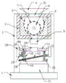
Fig. 1 is a schematic sectional structure view of an ore crushing device for mining of the present invention;
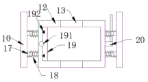
FIG. 2 is a schematic top view of the screen frame of the present invention;
fig. 3 is an enlarged schematic view of the structure of fig. 1 at the circle.
Wherein: 1-a base; 2-mounting a base; 3-a crushing box; 4-a feed hopper; 5, fixing blocks; 6-a crushing roller; 7-crushing the bulges; 8-fixing the bulge; 9-a blanking pipe; 10-fixing the plate; 11-a guide bar; 12-a screening frame; 13-a moving block; 14-a screening plate; 15-sieving holes; 16-large particle outlet; 17-a telescopic rod; 18-a spring; 19-a baffle plate; 20-eccentric mass; 21-fine material receiving box; 31-blanking gap; 32-a discharge gap; 191-a limit circular plate; 192-T shaped guide rails; 193-screw.
Detailed Description
As shown in fig. 1-3, the utility model discloses an ore crushing device for mining, include: the crushing device comprises a base 1, a mounting seat 2, a crushing box 3, a feed hopper 4, fixed blocks 5, a crushing roller 6, crushing protrusions 7, fixed protrusions 8, a blanking pipe 9, a fixed plate 10, a guide rod 11, a screening frame 12, a moving block 13, a screening plate 14, a screening hole 15, a large particle outlet 16, a telescopic rod 17, a spring 18, a baffle 19, an eccentric block 20 and a fine material receiving box 21, wherein the inner side of the upper end face of the base 1 is vertically and fixedly connected with the mounting seat 2, the top of the outer end face of the mounting seat 2 is fixedly connected with the crushing box 3, the top of the crushing box 3 is fixedly connected with the feed hopper 4, the inner part of the feed hopper 4 is communicated with the inner part of the crushing box 3, the left side and the right side of the inner part of the crushing box 3 are fixedly connected with the fixed blocks 5, the inner end face and the outer end face of the fixed blocks 5 are respectively attached to the inner walls of the inner side and the outer side of the crushing box 3, the end face of one opposite side of the two fixed blocks 5 is of an inward-concave cambered surface structure, the crushing roller 6 is rotatably mounted between the two fixed blocks 5, a crushing motor for driving the crushing roller 6 to rotate is assembled on the inner end face of the mounting seat 2, crushing protrusions 7 are uniformly and fixedly connected on the outer peripheral face of the crushing roller 6, fixing protrusions 8 are also uniformly and fixedly connected on the inner concave face of the fixing block 5, the distance between the inner concave face of the fixing block 5 and the outer wall of the crushing roller 6 is gradually reduced from top to bottom, a blanking pipe 9 is connected to the bottom of the crushing box 3, a discharging opening 32 is formed in the position, corresponding to the blanking pipe 9, of the bottom of the crushing box 3, a fixing plate 10 is fixedly connected to the left side and the right side of the lower portion of the outer end face of the mounting seat 2 respectively, two guide rods 11 are fixedly connected between the two fixing plates 10 in parallel, the mounting heights of the two guide rods 11 are consistent and are respectively arranged on the inner side and the outer side of the fixing plate 10, a screening frame 12 is arranged below the guide rods 11, the lower end of the blanking pipe 9 points to the center of the screening frame 12, and a moving block 13 is fixedly connected to the centers of the top portions of the inner side wall and the outer side of the screening frame 12 respectively, the movable blocks 13 are provided with sliding holes matched with the guide rods 11, the two movable blocks 13 are respectively connected with the guide rods 11 on the inner side and the outer side in a sliding manner through holes, a screening plate 14 is obliquely and fixedly connected inside the screening frame 12, the left side wall of the screening frame 12 is provided with a large particle outlet 16, the left side of the screening plate 14 is downward inclined and extends out from the large particle outlet 16 on the left side wall of the screening frame 12, the part of the screening plate 14, which is arranged inside the screening frame 12, is uniformly provided with screening holes 15, the inner side and the outer side of the left end surface of the screening frame 12 are respectively and fixedly connected with a telescopic rod 17, the right end surface of the screening frame 12, which corresponds to the position of the left telescopic rod 17, is also and fixedly connected with a telescopic rod 17, the other end, which is not connected with the screening frame 12, is fixedly connected with the fixed plate 10 on the same side, the outer side of each telescopic rod 17 is sleeved with a spring 18, the inner side and the outer side of the left side of the screening frame 12 are respectively and fixedly connected with a T-shaped guide rail 192, open on the 19 left end face of baffle has the recess that matches with T type guide rail 192, baffle 19 passes through recess and T type guide rail 192 sliding fit, and when the 19 lower extremes of baffle and the laminating of screening board 14, 19 up end of baffle and the 12 up end parallel and level of screening frame, the 12 right sides of screening frame set up an eccentric block 20, eccentric block 20 is through installing axle and 2 switchovers of inboard mount pad, install a drive eccentric block 20 pivoted driving motor on the terminal surface in the mount pad 2, the laminating of 20 outer walls of eccentric block and the 12 right side walls of screening frame places a thin material on the base 1 of placing screening frame 12 below and connects workbin 21.
The top wall of the crushing box 3 is provided with a blanking gap 31 for communicating the feed hopper 4 with the inside of the crushing box 3.
The two fixed blocks 5 are symmetrically arranged at the left side and the right side of the crushing roller 6.
An output shaft of a crushing motor arranged on the inner end surface of the mounting base 2 sequentially penetrates through the mounting base 2 and the inner side wall of the crushing box 3 outwards and then is fixedly connected with the inner end of the crushing roller 6.
The top center of the left side wall of the screening frame 12 is in threaded connection with a limiting circular plate 191, the right side of the limiting circular plate 191 extends to the upper side of the baffle 19, a screw 193 is fixedly connected to the lower end face of the limiting circular plate 191, a threaded hole matched with the screw 193 is formed in the position, corresponding to the screw 193, of the left side wall of the screening frame 12, the screw 19 is connected with the threaded hole, and the baffle 19 is tightly pressed by the right side of the limiting circular plate 191.
The lower end face of the baffle plate 19 is of an inclined plane structure, and the inclined plane can be completely attached to the screening plate 14.
The utility model discloses an implement like this: when in use, the ore to be crushed is added from the feed hopper 4, the crushing motor is started, the crushing motor drives the crushing roller 6 to rotate, the crushing bulge 7 rotating in this way can be matched with the fixed bulge 8 to crush the ores, and because the distance between the outer wall of the crushing roller 6 and the inner cambered surface of the fixed block 5 is gradually reduced, can ensure that the ore can only pass through the lower part of the crushing roller 6 after being crushed to a certain size, ensures the crushing effect, the crushed ore falls onto the screening plate 14 in the screening frame 12 from the blanking pipe 9, the driving motor is started, the driving motor drives the eccentric block 20 to rotate, under the action of the eccentric block 20 and the spring 18, the screening frame 12 can swing left and right to improve the screening effect, and the baffle 19 blocks the large granule outlet 16, the fine materials can be completely screened out, the baffle 19 can be removed to discharge the large particles after the screening is finished, and the fine materials can fall into the fine material collecting box 21 in the screening process. Adopt this technical scheme, because screening mechanism arranges the 2 outsides of mount pad in, can be swift clear up or maintain it, it is more convenient to operate, has guaranteed the efficiency of ore processing.
Finally, it should be noted that: the above embodiments are only used for illustrating the present invention and do not limit the technical solution described in the present invention; thus, while the present invention has been described in detail with reference to the various embodiments thereof, it will be understood by those skilled in the art that various changes may be made and equivalents may be substituted; all such modifications and variations are intended to be included herein within the scope of this disclosure and the present invention and within the scope and spirit of the following claims.