CN214906400U - Floor brush - Google Patents
Floor brush Download PDFInfo
- Publication number
- CN214906400U CN214906400U CN202120267763.8U CN202120267763U CN214906400U CN 214906400 U CN214906400 U CN 214906400U CN 202120267763 U CN202120267763 U CN 202120267763U CN 214906400 U CN214906400 U CN 214906400U
- Authority
- CN
- China
- Prior art keywords
- worm
- floor
- component
- output shaft
- floor brush
- Prior art date
- Legal status (The legal status is an assumption and is not a legal conclusion. Google has not performed a legal analysis and makes no representation as to the accuracy of the status listed.)
- Active
Links
- 239000000428 dust Substances 0.000 claims abstract description 55
- 238000010521 absorption reaction Methods 0.000 claims abstract description 16
- 230000005540 biological transmission Effects 0.000 claims description 14
- 230000001681 protective effect Effects 0.000 claims description 7
- 238000005201 scrubbing Methods 0.000 abstract description 8
- 239000004744 fabric Substances 0.000 description 6
- 238000007790 scraping Methods 0.000 description 3
- 238000010586 diagram Methods 0.000 description 2
- 238000004140 cleaning Methods 0.000 description 1
- 230000004048 modification Effects 0.000 description 1
- 238000012986 modification Methods 0.000 description 1
Images



Landscapes
- Nozzles For Electric Vacuum Cleaners (AREA)
Abstract
The utility model relates to a floor brush, including the casing, wipe ground part, driver part, drive assembly, wipe ground part setting in the bottom of casing, driver part sets up the inside at the casing, driver part through drive assembly with wipe ground part and wipe ground part work with the drive mutually, the dust absorption mouth has been seted up to the front portion of casing, the rear portion of casing is provided with the dust catcher interface, be linked together through the dust absorption pipe between dust absorption mouth, the dust catcher interface, the dust absorption pipe setting of telling is in the inside of casing, the dust absorption pipe is walked around from driver part's lateral part. The utility model discloses improve on the basis of current scrubbing brush, with the dust absorption pipe setting in the casing, it is not fragile to protect the dust absorption pipe, and the dust absorption pipe is walked around from driver part's lateral part, can reduce the holistic thickness of scrubbing brush, does not walk around from driver part from top to bottom and can adopt thicker dust absorption pipe, satisfies portable and efficient requirement simultaneously.
Description
Technical Field
The utility model relates to a clean field, concretely relates to scrubbing brush.
Background
In modern society, a dust collector is a common dust collecting tool for families, and the working principle of the dust collector is that a blade is driven to rotate at a high speed by a motor, so that air negative pressure is generated in a sealed shell to absorb dust. In order to meet the requirements of different cleaning operations, the floor brushes of the dust collector have various types, and people can select the floor brushes according to the requirements to remove dust of various articles.
In the daily cleanness of family life, the difference of scrubbing brush can influence the convenience and the high efficiency of dust catcher performance, the scrubbing brush of current handheld dust catcher is in order to satisfy the strong requirement of clean ability at first, often the bulk ratio is bigger, generally all be more than 50m, minimum also be the thickness more than 45mm, and sound is noisy, this can lead to too thickly be not convenient for handheld, some products are for portable in addition, adopt flat dust absorption pipe to walk around from drive unit's top or below, big rubbish is difficult to pass through, the dust collection efficiency is low, very influence user experience.
Disclosure of Invention
The utility model aims at providing a floor brush.
In order to achieve the above purpose, the utility model adopts the technical scheme that:
a floor brush comprises a shell, a floor wiping component, a driving component and a transmission component, wherein the floor wiping component is arranged at the bottom of the shell, the driving component is arranged in the shell, the driving component and the floor wiping component drive the floor wiping component to work through the transmission component, a dust suction opening is formed in the front of the shell, a dust collector interface is arranged at the rear of the shell, the dust suction opening and the dust collector interface are communicated through a dust suction conduit, the dust suction conduit is arranged in the shell, and the dust suction conduit bypasses the side part of the driving component.
Preferably, the driving part is a double-worm motor, the double-worm motor comprises a motor main body and a worm, the motor main body is provided with a first output shaft and a second output shaft, the first output shaft and the second output shaft are respectively connected with the worm, and the axial lines of the first output shaft and the second output shaft are superposed with the axial line of the worm; the transmission assembly comprises a rotating shaft and a gear sleeved on the rotating shaft, the rotating shaft is connected with the floor mopping component, and the worm is meshed with the gear.
Further preferably, the driving member further includes an elastic member, and the elastic member is disposed between the worm and each of the first output shaft and the second output shaft, and the elastic member adjusts the worm in a radial direction thereof.
Further preferably, the thickness of the motor body is not more than 40 mm.
Further preferably, the rotating shaft and the floor wiping part are connected through a plurality of fasteners.
Further preferably, the driving part further comprises a protective shell, and the protective shell is wrapped outside the worm and the gear.
Preferably, the floor mopping component comprises a first rotating disc and a second rotating disc, and the driving component is connected with the first rotating disc and the second rotating disc through the transmission assembly.
Further preferably, the first rotating disc and the second rotating disc are respectively positioned at two sides of the driving part.
Further preferably, the floor mopping component further comprises wiping cloths arranged on the first rotating disc and the second rotating disc.
Preferably, the cross section of the dust suction duct is circular.
Preferably, the floor brush further comprises a roller arranged at the bottom of the shell.
Because of the application of the technical scheme, compared with the prior art, the utility model has the following advantages:
the utility model discloses improve on the basis of current scrubbing brush, with the dust absorption pipe setting in the casing, it is not fragile to protect the dust absorption pipe, and the dust absorption pipe is walked around from driver part's lateral part, can reduce the holistic thickness of scrubbing brush, does not walk around from driver part from top to bottom and can adopt thicker dust absorption pipe, satisfies portable and efficient requirement simultaneously.
Drawings
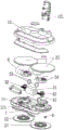
FIG. 1 is an exploded view of the present embodiment;
FIG. 2 is a schematic combination diagram of the present embodiment;
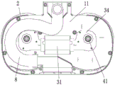
FIG. 3 is a top view of the present embodiment (cover not shown);
FIG. 4 is a bottom view of the present embodiment (the wipe not shown);
fig. 5 is a schematic diagram of the driving unit (not shown in the protection case) and the transmission assembly in this embodiment.
In the above drawings: 11. a base; 111. a dust suction port; 12. a cover body; 121. a dust collector interface; 2. a floor wiping component; 21. a first turntable; 22. a second turntable; 23. wiping cloth; 31. a motor main body; 32. a worm; 33. an elastic member; 34. a protective shell; 41. a rotating shaft; 42; a gear; 5. a fastener; 6. a roller; 7. a rubber scraping strip; 8. a dust suction duct.
Detailed Description
The technical solution of the present invention will be described clearly and completely with reference to the accompanying drawings, and obviously, the described embodiments are some, but not all embodiments of the present invention. Based on the embodiments in the present invention, all other embodiments obtained by a person skilled in the art without creative work belong to the protection scope of the present invention.
In the description of the present invention, it should be noted that the terms "center", "upper", "lower", "left", "right", "vertical", "horizontal", "inner", "outer", and the like indicate orientations or positional relationships based on the orientations or positional relationships shown in the drawings, and are only for convenience of description and simplification of description, but do not indicate or imply that the device or element referred to must have a specific orientation, be constructed and operated in a specific orientation, and thus, should not be construed as limiting the present invention. Furthermore, the terms "first," "second," and "third" are used for descriptive purposes only and are not to be construed as indicating or implying relative importance.
In the description of the present invention, it is to be noted that, unless otherwise explicitly specified or limited, the terms "mounted," "connected," and "connected" are to be construed broadly, and may be, for example, fixedly connected, detachably connected, or integrally connected; can be mechanically or electrically connected; they may be connected directly or indirectly through intervening media, or they may be interconnected between two elements. The specific meaning of the above terms in the present invention can be understood in specific cases to those skilled in the art.
As shown in figure 1, the floor brush comprises a shell, a floor wiping component 2, a driving component and a transmission assembly, wherein the floor wiping component 2 is arranged at the bottom of the shell, the driving component is arranged inside the shell, and the driving component and the floor wiping component drive the floor wiping component 2 to work through the transmission assembly.
As shown in fig. 1-3, the housing includes a base 11 at the bottom and a cover 12 covering the base 11, a dust suction opening 111 is formed at the front of the housing, specifically in the middle of the front of the base 11, a dust suction connector 121 is formed at the rear of the housing, specifically in the middle of the rear of the cover 12, the dust suction opening 111 and the dust suction connector 121 are communicated with each other through a dust suction pipe 8, the dust suction pipe 8 is disposed inside the housing, the dust suction pipe 8 is bypassed from the side of the driving part, and in this embodiment, the dust suction pipe 8 is bypassed from one side of the driving part. Adopt the drive assembly of small volume, make the casing in have bigger space, dust absorption pipe 8 adopts the cross-section to be circular hose and walks around from one side of drive assembly, both can reduce the holistic thickness of scrubbing brush, and circular shape can bring bigger runner simultaneously, and the rubbish of being convenient for passes through.
As shown in fig. 1, 3 and 5, the driving part is a double worm motor, and the double worm motor includes a motor body 31, a worm 32 and an elastic member 33. The motor body 31 is a motor, and has a thickness of not more than 40mm, and in the present embodiment, the thickness of the motor body 31 is 38 mm. The motor main body 31 is arranged on the base 11, the dust collector interface 121 is provided with a wire interface and is connected with the motor main body 31, the left side and the right side of the motor main body 31 are provided with a first output shaft and a second output shaft, the first output shaft and the second output shaft are respectively connected with a worm 32, and the axial leads of the first output shaft and the second output shaft are coincided with the axial lead of the worm 32. The worm 32 extends to the left and right sides and is matched with the transmission assembly, and the elastic piece 33 is an elastic rubber piece and is arranged between the worm 32 and the first output shaft and the second output shaft, so that the worm 32 can be adjusted in the radial direction.
As shown in fig. 1, 3 and 5, the transmission assembly includes a rotating shaft 41 and a gear 42. The lower end of the rotating shaft 41 penetrates through the base 11 to be connected with the floor mopping component 2, the gear 42 is sleeved at the upper end of the rotating shaft 41, and the worm 32 is meshed with the gear 42. The worm 32 is automatically adapted to the running of the gear 42 by utilizing the automatic adjusting function of the elastic part 33, thereby achieving the running stability of the whole product, reducing the noise and prolonging the service life of the gear 42.
As shown in fig. 1 and 3, the driving part further includes a protective casing 34, and the protective casing 34 covers the worm 32 and the gear 42, so as to prevent the worm 32 and the gear 42 from being damaged when the product is vibrated or impacted.
As shown in fig. 1 and 4, the floor wiping component 2 includes a first rotating disk 21, a second rotating disk 22, and a wiping cloth 23, and the driving component is connected to the first rotating disk 21 and the second rotating disk 22 through a transmission component and drives the first rotating disk 21 and the second rotating disk 22 to rotate. The first rotating disk 21 and the second rotating disk 22 are located at the bottom of the base 11 and located at two sides of the driving part respectively, the first rotating disk 21 and the second rotating disk 22 are connected to the lower end of the rotating shaft 41 respectively and fixed through a plurality of fasteners 5, in this embodiment, the fasteners 5 are screws, and each rotating shaft 41 is connected with two screws, so that the overall operation stability is maintained, and the volume can be reduced. The bottoms of the first rotating disc 21 and the second rotating disc 22 are respectively connected with a wiping cloth 23 with the same shape, the wiping cloths 23 can be connected through a magic tape, and the first rotating disc 21 and the second rotating disc 22 are covered by the wiping cloth 23.
As shown in fig. 1 and 5, the floor brush further comprises a roller 6 and a rubber scraping strip 7 which are arranged at the bottom of the base 11. The roller 6 is positioned at the rear end of the bottom of the base 11, can support the whole floor brush and is convenient for dragging the floor brush on the ground. The rubber scraping strip 7 is positioned at the front end of the bottom of the base 11, extends along the left side and the right side, is arranged between the dust collection opening 111 and the wiping cloth 23, helps to collect garbage to the vicinity of the dust collection opening 111, and can also scrape garbage which is not easy to be wiped off by the wiping cloth 23 on the ground.
The above embodiments are only for illustrating the technical concept and features of the present invention, and the purpose of the embodiments is to enable people skilled in the art to understand the contents of the present invention and to implement the present invention, which cannot limit the protection scope of the present invention. All equivalent changes and modifications made according to the spirit of the present invention should be covered by the protection scope of the present invention.
Claims (10)
1. A floor brush comprises a shell, a floor wiping component, a driving component and a transmission component, wherein the floor wiping component is arranged at the bottom of the shell, the driving component is arranged inside the shell, the driving component and the floor wiping component drive the floor wiping component to work through the transmission component, a dust suction opening is formed in the front of the shell, a dust collector interface is arranged at the rear of the shell, and the dust suction opening and the dust collector interface are communicated through a dust suction conduit, and the floor brush is characterized in that: the dust suction pipe is arranged in the shell and bypasses from the side part of the driving part.
2. A floor brush as claimed in claim 1, wherein: the driving part is a double-worm motor, the double-worm motor comprises a motor main body and a worm, the motor main body is provided with a first output shaft and a second output shaft, the first output shaft and the second output shaft are respectively connected with the worm, and the axial leads of the first output shaft and the second output shaft are superposed with the axial leads of the worm; the transmission assembly comprises a rotating shaft and a gear sleeved on the rotating shaft, the rotating shaft is connected with the floor mopping component, and the worm is meshed with the gear.
3. A floor brush as claimed in claim 2, wherein: the driving part also comprises an elastic part, the elastic parts are respectively arranged between the worm and the first output shaft and between the worm and the second output shaft, and the elastic parts enable the worm to be adjusted in the radial direction of the worm.
4. A floor brush as claimed in claim 2, wherein: the thickness of the motor body is not more than 40 mm.
5. A floor brush as claimed in claim 2, wherein: the rotating shaft is connected with the floor mopping component through a plurality of fasteners.
6. A floor brush as claimed in claim 2, wherein: the drive part also comprises a protective shell, and the protective shell is covered outside the worm and the gear.
7. A floor brush as claimed in claim 1, wherein: the floor mopping component comprises a first rotating disc and a second rotating disc, and the driving component is connected with the first rotating disc and the second rotating disc through the transmission component.
8. A floor brush as claimed in claim 7, wherein: the first rotating disc and the second rotating disc are respectively positioned on two sides of the driving part.
9. A floor brush as claimed in claim 7, wherein: the floor mopping component also comprises wiping cloths arranged on the first rotating disc and the second rotating disc.
10. A floor brush as claimed in claim 1, wherein: the section of the dust absorption conduit is circular.
Priority Applications (1)
| Application Number | Priority Date | Filing Date | Title |
|---|---|---|---|
| CN202120267763.8U CN214906400U (en) | 2021-01-29 | 2021-01-29 | Floor brush |
Applications Claiming Priority (1)
| Application Number | Priority Date | Filing Date | Title |
|---|---|---|---|
| CN202120267763.8U CN214906400U (en) | 2021-01-29 | 2021-01-29 | Floor brush |
Publications (1)
| Publication Number | Publication Date |
|---|---|
| CN214906400U true CN214906400U (en) | 2021-11-30 |
Family
ID=79100975
Family Applications (1)
| Application Number | Title | Priority Date | Filing Date |
|---|---|---|---|
| CN202120267763.8U Active CN214906400U (en) | 2021-01-29 | 2021-01-29 | Floor brush |
Country Status (1)
| Country | Link |
|---|---|
| CN (1) | CN214906400U (en) |
-
2021
- 2021-01-29 CN CN202120267763.8U patent/CN214906400U/en active Active
Similar Documents
| Publication | Publication Date | Title |
|---|---|---|
| WO2004062454A3 (en) | Vacuum cleaner with cleaning pad | |
| MXPA03002065A (en) | Vacuum cleaner with reversible rotary agitator. | |
| CN113749580A (en) | A combined washing machine | |
| CN210631153U (en) | Vacuum cleaner with a vacuum cleaner head | |
| CN110584532A (en) | Dust collector with rolling brush hair winding automatic cutting structure | |
| CN2735924Y (en) | Hand-held type dust-collecting air-blowing cleaner | |
| CN112806925A (en) | Clean power device and cleaning machine thereof | |
| CN209301024U (en) | Sweeping robot and its cleaning device | |
| CN216417032U (en) | Dust collector | |
| CN105455746B (en) | Dust absorption formula machine of sweeping floor | |
| CN209932599U (en) | Dust absorption mopping all-in-one machine | |
| CN115299808B (en) | Dust collector rolling brush suitable for deep garbage cleaning | |
| CN112006601A (en) | Anti-collision household dust collector capable of avoiding blockage | |
| CN113083842B (en) | Dust recovery device and processing equipment comprising same | |
| CN214906387U (en) | Suction and mopping integrated dust collector | |
| US6266846B1 (en) | Vacuum cleaner | |
| CN212346416U (en) | Sweeping device and sweeping robot | |
| CN212310199U (en) | Scrap removing device of welding detection device of boiler pressure container | |
| CN212234330U (en) | Floor wiping brush head with dust collection function | |
| CN201987459U (en) | Multifunctional dust catcher | |
| CN211093752U (en) | Household cleaning device | |
| CN114052554A (en) | Dust collector floor brush easy to pull backwards | |
| CN2920142Y (en) | Floor dust cleaner | |
| CN217488505U (en) | Dust collector floor brush easy to clean | |
| CN219813981U (en) | Multifunctional household dust collector |
Legal Events
| Date | Code | Title | Description |
|---|---|---|---|
| GR01 | Patent grant | ||
| GR01 | Patent grant |