SUMMERY OF THE UTILITY MODEL
An object of the utility model is to provide a protective structure to the foreign matter such as condensation easily receives in the module socket end position of solving prior art invades and leads to the impaired technical problem of battery module.
In order to achieve the above object, the utility model adopts the following technical scheme: the utility model provides a protective structure is applied to on the battery module, and the battery module has the positive pole and draws forth end, negative pole and draw forth end and grafting end, and protective structure includes: the protective structure body is provided with an electrode leading-out protective part used for covering the positive electrode leading-out end and/or the negative electrode leading-out end and an inserting protective part used for covering the inserting end, and the inserting protective part is connected with the electrode leading-out protective part; and the fixing structure is arranged on the protective structure body and used for fixing the protective structure body on the battery module.
The utility model discloses in foretell technical scheme, following technological effect or advantage have at least: the protection structure provided by the utility model is provided with the protection structure body and the fixed structure arranged on the protection structure body, and the protection structure body is provided with the electrode leading-out protection part and the inserting protection part which are connected, the protective structure body can be fixed on the battery module through the fixing structure, so that the electrode leading-out protective part is covered on the positive electrode leading-out end and/or the negative electrode leading-out end of the battery module to protect the battery module, the inserting protective part is covered on the inserting end to protect the battery module, can effectively prevent external foreign matters from invading the positive electrode leading-out end, the negative electrode leading-out end and the inserting end to cause damage, and can prevent that positive pole from drawing forth the end and/or the negative pole is drawn forth the end and is drawn forth the junction with external connecting piece, peg graft end and external plug connector junction and receive the invasion of foreign matter such as condensation and lead to the safety risk such as short circuit, can effectively improve the security of battery module and battery package. Simultaneously, draw forth the protection part and peg graft the protection part and connect in an organic whole because of the electrode, be fixed in the battery module with the protection structure body through fixed knot structure and can realize simultaneously that the positive pole draws forth end, negative pole and draws forth end and peg graft the end and protect, the convenience is high, and has practiced thrift the design and the manufacturing cost of spare part.
In one embodiment, the electrode leading-out protection part comprises a positive electrode leading-out protection part used for covering the positive electrode leading-out end and a negative electrode leading-out protection part used for covering the negative electrode leading-out end, and the positive electrode leading-out protection part and the negative electrode leading-out protection part are respectively connected to two ends of the insertion protection part.
Through adopting above-mentioned technical scheme, be fixed in the battery module with the protective structure body through fixed knot and draw forth end, negative pole to the positive pole of battery module simultaneously and draw forth the end and peg graft the end and protect, the convenience is high, and the positive pole draws forth protection portion and negative pole and draws forth protection portion and connect respectively in the both ends of grafting protection portion, be convenient for with the battery module on the positive pole draw forth end, the negative pole draw forth the position looks adaptation of end and grafting end.
In one embodiment, the electrode leading-out protection part comprises a positive electrode leading-out protection part, the positive electrode leading-out protection part is provided with a first cavity used for covering the positive electrode leading-out end, and a first leading-out opening communicated with the first cavity is formed in the positive electrode leading-out protection part; and/or the electrode leading-out protection part comprises a negative electrode leading-out protection part, the negative electrode leading-out protection part is provided with a second cavity used for covering the negative electrode leading-out end, and a second leading-out opening communicated with the second cavity is formed in the negative electrode leading-out protection part.
By adopting the technical scheme, the first cavity can protect the positive leading-out end, and the first leading-out port is beneficial to the fact that an external connecting piece extends into the first cavity to be connected with the positive leading-out end, so that the joint of the external connecting piece and the positive leading-out end can be protected; the second cavity can be protected the negative pole and draw forth the end, and the second is drawn forth the mouth and is favorable to external connecting piece to stretch into the second cavity and draw forth the end with the negative pole and be connected to do benefit to and protect its junction.
In one embodiment, the number of the first leading-out ports is at least two, and an included angle is formed between the opening direction of one first leading-out port and the opening direction of the other first leading-out port; and/or the number of the second leading-out ports is at least two, and an included angle is formed between the opening direction of one second leading-out port and the opening direction of the other second leading-out port.
By adopting the technical scheme, the at least two first leading-out ports are arranged, and an included angle is formed between the opening direction of one first leading-out port and the opening direction of the other first leading-out port, so that the external connecting piece can conveniently extend into the first cavity from different directions to be connected with the positive leading-out end, and the adaptability and the flexibility of leading out the positive electrode can be improved; the opening direction of the second leading-out port and the opening direction of the other second leading-out port form an included angle, so that an external connecting piece can conveniently extend into the second cavity from different directions to be connected with the negative leading-out end, and the adaptability and the negative leading-out flexibility can be improved.
In one embodiment, the electrode leading-out protection part is provided with a first shielding part which detachably shields the first leading-out opening, and the first shielding part is integrally formed with the positive electrode leading-out protection part or detachably connected with the positive electrode leading-out protection part; and/or the electrode leading-out protection part is provided with a second shielding part which detachably shields the second leading-out opening, and the second shielding part and the negative leading-out protection part are integrally formed or detachably connected with the negative leading-out protection part.
Through adopting above-mentioned technical scheme, shelter from the first mouth of drawing forth through setting up removable first occlusion part, do benefit to the protection in battery module storage and transportation, prevent that the foreign matter from drawing forth the mouth invasion positive pole by first and drawing forth the end to do benefit to the battery module and can get rid of first occlusion part and make external connecting piece stretch into first cavity and draw forth the end with the positive pole and be connected when assembling into the battery package; lead out the mouth through setting up detachable second occlusion part to the second and shelter from, do benefit to the protection in battery module storage and transportation, prevent that the foreign matter from leading out the mouth by the second and invading the negative pole and leading out the end to do benefit to battery module and can get rid of the second occlusion part and make external connection spare stretch into the second cavity and draw out the end with the negative pole when assembling into the battery package and be connected.
In one embodiment, the insertion protection part is provided with a third cavity for covering the insertion end, and a third leading-out opening communicated with the third cavity is formed in the insertion protection part.
Through adopting above-mentioned technical scheme, the third cavity can protect the grafting end of battery module, and the third is drawn forth the mouth and is favorable to outside plug connector to stretch into the third cavity and be connected with the grafting end to do benefit to and protect its junction.
In one embodiment, the number of the third leading-out ports is at least two, and an included angle is formed between the opening direction of one third leading-out port and the opening direction of the other third leading-out port.
By adopting the technical scheme, the at least two third leading-out ports are arranged, the opening direction of one third leading-out port and the opening direction of the other third leading-out port form an included angle, so that the external plug connector can extend into the third cavity from different directions to be connected with the plug end, and the adaptability and the connection flexibility can be improved.
In one embodiment, the plugging protection portion has a third shielding portion, the third shielding portion detachably shields the third outlet, and the third shielding portion and the plugging protection portion are integrally formed or detachably connected to the plugging protection portion.
Through adopting above-mentioned technical scheme, drawing forth the mouth to the third through setting up removable third occlusion part and sheltering from, do benefit to the protection in battery module storage and transportation, prevent that the foreign matter from drawing forth a mouthful invasion grafting end by the third to do benefit to battery module and can get rid of the third occlusion part and make outside plug connector stretch into the third cavity and be connected with the grafting end when assembling into the battery package.
In one embodiment, the protective structure body is provided with a connecting part, the connecting part is connected between the electrode leading-out protective part and the inserting protective part, and the fixing structure is arranged on the connecting part.
Through adopting above-mentioned technical scheme, connecting portion connect between electrode extraction guard portion and the grafting guard portion, and fixed knot constructs and sets up on connecting portion, therefore fixed knot constructs not only to cause the influence to the protection of electrode extraction guard portion and grafting guard portion, and can realize the fixed of protective structure body under the condition that does not occupy the peripheral space of battery module.
In one embodiment, the battery module has a snap-fit portion, and the fixing structure is an elastic snap-fit portion for snap-fitting with the snap-fit portion of the battery module.
Through adopting above-mentioned technical scheme, fixed knot constructs for elasticity block portion, and its elastic deformation of being convenient for and be connected and fix the protective structure body with the block cooperation looks block of battery module, and be convenient for install and dismantle.
In one embodiment, the elastic clamping part comprises a plurality of elastic deformation bodies, each elastic deformation body is provided with a root and an end capable of elastically deforming relative to the root, the root of each elastic deformation body is connected to the protective structure body, and a gap is formed between the ends of two adjacent elastic deformation bodies.
Through adopting above-mentioned technical scheme, the tip through a plurality of elasticity morphs takes place to deform and is connected with the block cooperation portion block of battery module, can improve the connection convenience to the protective structure body.
In one embodiment, the same side of the electrode leading-out protection part and the inserting protection part is provided with a first end face used for abutting against one surface of the battery module, the same other side of the electrode leading-out protection part and the inserting protection part is provided with a second end face arranged opposite to the first end face, the protection structure body is provided with a flow guide part, the flow guide part is connected to the electrode leading-out protection part and the inserting protection part, and the flow guide part is obliquely arranged from the first end face to the second end face.
Through adopting above-mentioned technical scheme, when drop of water such as condensation drips on the protective structure body, the water conservancy diversion of drop accessible water conservancy diversion portion and flow by first terminal surface towards the second terminal surface prevents that the drop of water from along permeating the module between first terminal surface and the battery module inside and causing the safety risk, can further improve safety protection performance.
In one embodiment, the protective structure body is provided with an electrode mark, and the electrode mark is arranged on the electrode leading-out protective part.
Through adopting above-mentioned technical scheme, the positive pole of being convenient for discernment battery module is drawn forth end, negative pole and is drawn forth end, plug connector, avoids battery module to appear discerning the mistake and carry out some improper deposits and operate and bring the safety risk when storing, transporting and assembling operating personnel.
Another object of the utility model is to provide a module end plate, the module end plate includes: the end plate body is provided with an electrode mounting port for mounting a positive electrode leading-out end and/or a negative electrode leading-out end of the battery module and a plug-in mounting port for mounting a plug-in end of the battery module; and the protective structure of any of the above embodiments, the fixed structure of the protective structure is connected to the end plate body, and the electrode leading-out protective part cover of the protective structure is arranged at the electrode arrangement opening, and the inserting protective part cover of the protective structure is arranged at the inserting arrangement opening.
The utility model discloses foretell technical scheme, owing to adopted foretell protective structure, can prevent effectively that external foreign matter from invading the positive pole of battery module and drawing forth end, negative pole and draw forth the end, peg graft the end and lead to it impaired to can prevent that the positive pole from drawing forth end and/or negative pole and draw forth end and external connection spare junction, peg graft end and external plug connector junction receive the invasion of foreign matter such as condensation and lead to appearing safety risks such as short circuit, can effectively improve the security of battery module and battery package.
In one embodiment, the end plate body has a snap-fit portion, and the fixing structure is an elastic snap-fit portion snap-fitted with the snap-fit portion; an opening cavity is formed between the clamping matching part and the end plate body, the clamping matching part is provided with a connecting hole communicated with the opening cavity, and the elastic clamping part is clamped in the connecting hole.
Through adopting above-mentioned technical scheme, be convenient for convenient installation and dismantlement between protective structure and the module end plate, and be formed with the opening chamber because of between block cooperation portion and the end plate body, block cooperation portion has the connecting hole that is linked together with the opening chamber, elasticity block portion block in the connecting hole, when drop of water such as condensation drips on the protective structure body, and when permeating between elasticity block portion and the connecting hole, can flow to the opening chamber along the connecting hole, flow to the outside by the opening chamber again, prevent that the drop of water from appearing the safety risk through the electrical connection position, can further improve the security.
It is still another object of the present invention to provide a battery module, which includes the protection structure of any of the above embodiments or the module end plate of any of the above embodiments.
The utility model discloses foretell technical scheme, owing to adopted foretell protective structure or module end plate, can prevent effectively that external foreign matter from invading the positive pole of battery module and drawing forth the end, the negative pole draws forth the end, peg graft the end and lead to its impaired to can prevent that the positive pole from drawing forth end and/or negative pole and draw forth end and external connection spare junction, peg graft end and external plug connector junction receive the invasion of foreign matter such as condensation and lead to appearing safety risks such as short circuit, can effectively improve the security of battery module and battery package.
Still another object of the present invention is to provide a battery pack, which includes the above battery module.
The utility model discloses foretell technical scheme owing to adopted foretell battery module, can prevent that the positive pole from drawing forth end and/or negative pole and draw forth end and external connection spare junction, grafting end and external plug connector junction receive the invasion of foreign matter such as condensation and lead to the safety risks such as short circuit appearing, can effectively improve the security of battery package.
It is yet another object of the present invention to provide a vehicle including the above battery pack.
The utility model discloses foretell technical scheme owing to adopted foretell battery package, can prevent that the positive pole from drawing forth end and/or negative pole and draw forth end and external connection spare junction, grafting end and external plug connector junction receive the invasion of foreign matter such as condensation and lead to the safety risks such as short circuit appearing, can effectively improve the security of vehicle.
Detailed Description
Reference will now be made in detail to embodiments of the present invention, examples of which are illustrated in the accompanying drawings, wherein like reference numerals refer to the same or similar elements or elements having the same or similar function throughout. The embodiments described below with reference to the drawings are exemplary and intended to be used for explaining the present invention, and should not be construed as limiting the present invention.
In the description of the present invention, it is to be understood that the terms "length", "width", "upper", "lower", "front", "rear", "left", "right", "vertical", "horizontal", "top", "bottom", "inner", "outer", and the like indicate orientations or positional relationships based on those shown in the drawings, and are merely for convenience of description and simplicity of description, and do not indicate or imply that the device or element being referred to must have a particular orientation, be constructed and operated in a particular orientation, and thus, should not be construed as limiting the present invention.
Furthermore, the terms "first", "second" and "first" are used for descriptive purposes only and are not to be construed as indicating or implying relative importance or implicitly indicating the number of technical features indicated. Thus, a feature defined as "first" or "second" may explicitly or implicitly include one or more of that feature. In the description of the present invention, "a plurality" means two or more unless specifically limited otherwise.
In the present invention, unless otherwise expressly stated or limited, the terms "mounted," "connected," and "fixed" are to be construed broadly and may, for example, be fixedly connected, detachably connected, or integrally formed; can be mechanically or electrically connected; either directly or indirectly through intervening media, either internally or in any other relationship. The specific meaning of the above terms in the present invention can be understood according to specific situations by those skilled in the art.
Referring to fig. 1 to 4, an embodiment of the present invention provides a protection structure 100, applied to a battery module, the battery module has a positive terminal, a negative terminal and a plugging terminal, the positive terminal and the negative terminal can be electrically connected to an external connector (for example, the connector 300 shown in fig. 4) to facilitate the extraction of the positive terminal and the negative terminal of the battery module, the plugging terminal can be connected to an external connector (for example, the connector 400 shown in fig. 4), for example, the external plugging harness can be extracted from the plugging terminal of the sampling harness of the battery module. The protective structure 100 comprises a protective structure body 10 and a fixing structure 20, wherein:
the protective structure body 10 has an electrode leading-out protective part 11 and an insertion protective part 12, the electrode leading-out protective part 11 can cover a positive leading-out end, can cover a negative leading-out end, and can also cover a positive leading-out end and a negative leading-out end at the same time, the insertion protective part 12 is used for covering an insertion end, the insertion protective part 12 is connected with the electrode leading-out protective part 11, and the insertion protective part 12 and the electrode leading-out protective part 11 can be integrally formed or separately formed and connected. The protective structure body 10 may be in a cover shape, a hood shape, a box shape, etc., but is not limited thereto. The positive electrode leading-out end, the negative electrode leading-out end and the inserting end are covered to protect the periphery of the positive electrode leading-out end, the negative electrode leading-out end and the inserting end, so that foreign matters such as external condensation, water drops, impurities, sundries and residues are prevented from entering.
The fixing structure 20 is disposed on the protective structure body 10, and is used to fix the protective structure body 10 to the battery module, which may be fixed to a housing of the battery module, such as an end plate, or an insulating plate of the battery module, but is not limited thereto, and may also be fixed to the battery module without affecting the normal operation of the battery module and covered on the positive terminal, the negative terminal, or other positions of the plugging terminal. The fixing structure 20 may be an adhesive (e.g., an adhesive or a double-sided adhesive), a fastener (e.g., a bolt or a screw), a snap-in member (e.g., a fastener or an elastic fastener), or the like, but is not limited thereto, as long as the protective structure body 10 can be fixed to the fixing structure of the battery module.
The embodiment of the utility model provides a protective structure 100, through setting up protective structure body 10 and the fixed knot who sets up on protective structure body 10 constructs 20, and protective structure body 10 has the electrode that is connected and draws forth protection portion 11 and grafting protection portion 12, can fix protective structure body 10 to the battery module through fixed knot constructs 20, so that electrode draws forth protection portion 11 and covers and establish the positive pole leading-out end and the negative pole leading-out end of battery module and protect it, make grafting protection portion 12 cover and establish the grafting end and protect it, can prevent effectively that external foreign matter from invading positive pole leading-out end, negative pole leading-out end, grafting end and leading to its damage, and can prevent positive pole leading-out end and negative pole leading-out end and external connecting piece's junction, the junction of grafting end and external plug connector piece from the safety risks such as short circuit that the invasion of foreign matter such as condensation, water droplet, debris lead to appear, the safety of the battery module and the battery pack can be effectively improved. Simultaneously, draw forth protection part 11 and peg graft protection part 12 and connect in an organic whole because of the electrode, be fixed in protective structure body 10 in the battery module through fixed knot structure 20 and can realize simultaneously that the positive pole draws forth end, negative pole and draws forth the end and peg graft the end and protect, need not to set up a plurality of protective structure, and it is more convenient to install and dismantle, and overall structure steadiness is high to spare part's design and manufacturing cost have been practiced thrift.
In one embodiment, referring to fig. 1, the electrode leading-out protection part 11 includes a positive electrode leading-out protection part 111 for covering a positive electrode leading-out end and a negative electrode leading-out protection part 112 for covering a negative electrode leading-out end, the positive electrode leading-out protection part 111 and the negative electrode leading-out protection part 112 are respectively connected to two ends of the insertion protection part 12, the positive electrode leading-out protection part 111, the negative electrode leading-out protection part 112, and the insertion protection part 12 can be integrally formed, the overall structure stability is high, the manufacturing is completed at one time, the production and the processing are convenient, and of course, the positive electrode leading-out protection part 111, the negative electrode leading-out protection part 112, and the insertion protection part 12 can also be separately formed and connected. So set up, be fixed in protective structure body 10 through fixed knot structure 20 and draw forth the end to the positive pole of battery module simultaneously, the end is drawn forth to the negative pole and the end is drawn forth to the terminal and is pegged graft and protect, realizes once installation and multi-unit position protection, and the convenience is high, and the positive pole draws forth protection portion 111 and the negative pole draws forth protection portion 112 and connect respectively in the both ends of grafting protection portion, is convenient for draw forth the position looks adaptation of end, negative pole draw forth end and grafting end with the positive pole of battery module.
In one embodiment, referring to fig. 1, the electrode lead-out protection part 11 includes a positive electrode lead-out protection part 111, the positive electrode lead-out protection part 111 has a first cavity 1110 for covering a positive electrode lead-out end, and the positive electrode lead-out protection part 111 is provided with a first lead-out opening 1101 communicated with the first cavity 1110. By such arrangement, the first cavity 1110 can protect the positive lead-out end, and the first lead-out port 1101 facilitates an external connecting member (for example, a positive-negative pole bridging busbar) to extend into the first cavity 1110 from the first lead-out port 1101 and be connected with the positive lead-out end, thereby facilitating the first cavity 1110 to protect the joint of the external connecting member and the positive lead-out end.
For example, referring to fig. 1, the positive electrode lead-out protector 111 includes a first top wall portion 1111, a first side wall portion 1112 connected to the first top wall portion 1111, and a second side wall portion 1113 connected to the first top wall portion 1111, wherein the first top wall portion 1111, the first side wall portion 1112, and the second side wall portion 1113 enclose to form a first cavity 1110. Wherein, the first top wall portion 1111, the first side wall portion 1112 and the second side wall portion 1113 enclose the one side that has a side open-ended that closes and form and can support and lean on in the surface of the module tip of battery module and enclose rather than and establish the cavity that forms and carry out the protection to the positive pole leading-out terminal, can need not all to seal on four sides, can save material. Of course, the positive lead-out protector 111 may further include a third side wall portion connected to the first top wall portion 1111, such that the first top wall portion 1111, the first side wall portion 1112, the second side wall portion 1113, and the third side wall portion enclose to form a first cavity.
Further, in an embodiment, referring to fig. 1, the number of the first lead-out openings 1101 is at least two, and an included angle is formed between an opening direction of one first lead-out opening 1101 and an opening direction of another first lead-out opening 1101. For example, the first sidewall 1112 may be opened with a first exit 1101, the second sidewall 1113 may be opened with a first exit 1101, and an included angle is formed between the first sidewall 1112 and the second sidewall 1113. Through setting up at least two first drawing-out mouth 1101, and wherein the opening direction of a first drawing-out mouth 1101 and the opening direction of another first drawing-out mouth 1101 have the contained angle to form different drawing-out directions, be convenient for external connecting piece from different directions stretch into first cavity 1110 in with the positive pole lead out the end and be connected, can improve adaptability and positive pole and draw out the flexibility.
Further, in an embodiment, referring to fig. 1, the electrode leading-out protection portion 11 has a first shielding portion 113, the first shielding portion 113 is detachably shielded from the first leading-out opening 1101, and the first shielding portion 113 is integrally formed with the positive electrode leading-out protection portion 111 or detachably connected to the positive electrode leading-out protection portion 111. For example, when the first shielding portion 113 and the positive electrode lead-out protection portion 111 are integrally formed, a plurality of through holes can be formed between the first shielding portion 113 and the positive electrode lead-out protection portion 111, so that a grid structure is formed between the first shielding portion 113 and the positive electrode lead-out protection portion 111, namely, the first shielding portion 113 is connected through a plurality of connecting columns, the first shielding portion 113 can be directly torn off by a tool or a hand, the grid structure can not only guarantee the strength requirement, but also avoid the intrusion of foreign matters in the storage and transportation processes from touching the electric connection portion, and the foreign matters are removed during subsequent assembly so as to be inserted by an external connecting piece. For example, when the first shielding portion 113 is detachably connected to the positive electrode lead-out protector 111, the first shielding portion 113 may be connected to the positive electrode lead-out protector 111 by means of snap connection, screw or bolt connection, adhesion, or the like. Shelters from first leading out port 1101 through setting up removable first shielding part 113, does benefit to the protection in battery module storage and transportation, prevents that the foreign matter from leading out the positive pole by the invasion of first leading out port 1101 and leading out the end to do benefit to the battery module and can get rid of first shielding part 113 and make external connecting piece stretch into first cavity 1110 and be connected with the positive pole leading out the end when assembling into the battery package.
In one embodiment, referring to fig. 1, the electrode leading-out protection part 11 includes a negative leading-out protection part 112, the negative leading-out protection part 112 has a second cavity 1120 for covering a negative leading-out end, and the negative leading-out protection part 112 is provided with a second leading-out opening 1102 communicated with the second cavity 1120. So set up, the second cavity 1120 can be drawn forth the negative pole and be protected, and the second is drawn forth mouth 1102 and is favorable to external connecting piece to stretch into second cavity 1120 and draw forth the end with the negative pole and be connected, does benefit to and protects the junction that external connecting piece and negative pole were drawn forth the end.
For example, referring to fig. 1, the negative lead-out protection portion 112 includes a second top wall portion 1121, a fourth side wall portion 1122 connected to the second top wall portion 1121, and a fifth side wall portion 1123 connected to the second top wall portion 1121, and the second top wall portion 1121, the fourth side wall portion 1122, and the fifth side wall portion 1123 surround to form a second cavity 1120. One side of the second top wall portion 1121, the fourth side wall portion 1122, and the fifth side wall portion 1123, which is surrounded and formed with an opening on one side, can abut against the surface of the module end of the battery module and surround the surface to form a cavity for protecting the negative terminal, i.e., the cavity does not need to be sealed on all sides, which can save materials. Of course, the negative electrode lead-out protector 112 may further include a sixth side wall portion connected to the second top wall portion 1121, so that the second top wall portion 1121, the fourth side wall portion 1122, the fifth side wall portion 1123, and the sixth side wall portion surround to form a second cavity. Further, the electrode leading-out protection part 11 includes a positive electrode leading-out protection part 111 and a negative electrode leading-out protection part 112, and the second top wall part 1121 and the first top wall part 1111 may be integrally formed.
Further, in an embodiment, referring to fig. 1, the number of the second lead-out openings 1102 is at least two, and an included angle is formed between an opening direction of one second lead-out opening 1102 and an opening direction of another second lead-out opening 1102. For example, the fourth sidewall portion 1122 can be formed with a second lead-out opening 1102, the fifth sidewall portion 1123 can be formed with a second lead-out opening 1102, and an included angle is formed between the fourth sidewall portion 1122 and the fifth sidewall portion 1123. Through setting up at least two second and drawing out mouth 1102, and wherein the opening direction that a second was drawn out mouth 1102 and another second is drawn out the opening direction of mouth 1102 and is had the contained angle to form different directions of drawing out, be convenient for external connecting piece from different directions stretch into second cavity 1120 and be connected with the negative pole and draw out the end, can improve adaptability and negative pole and draw forth the flexibility.
Further, in an embodiment, referring to fig. 1, the electrode leading-out protection portion 11 has a second shielding portion 114, the second shielding portion 114 detachably shields the second leading-out opening 1102, and the second shielding portion 114 is integrally formed with the negative leading-out protection portion 112 or detachably connected to the negative leading-out protection portion 112. For example, when the second shielding portion 114 and the negative lead-out protection portion 112 are integrally formed, a plurality of through holes may be formed between the second shielding portion 114 and the negative lead-out protection portion 112, so that a grid structure is formed between the second shielding portion 114 and the negative lead-out protection portion 112, that is, the second shielding portion 114 may be directly torn off by a tool or a hand, i.e., connected by a plurality of connection columns. For example, when the second shielding portion 114 is detachably connected to the negative electrode lead-out protector 112, the second shielding portion 114 may be connected to the negative electrode lead-out protector 112 by means of engagement, screw or bolt connection, adhesion, or the like. The second leading-out port 1102 is shielded by the second shielding part 114 which is detachable, protection in the storage and transportation process of the battery module is facilitated, foreign matters are prevented from invading the negative leading-out end through the second leading-out port 1102, and the battery module can be prevented from being removed by the second shielding part 114 when being assembled into a battery pack, so that the external connecting piece extends into the second cavity 1120 to be connected with the negative leading-out end.
In an embodiment, referring to fig. 1, the plugging protection part 12 has a third cavity 120 for covering the plugging end, and the plugging protection part 12 is provided with a third outlet 1201 communicated with the third cavity 120. So set up, third cavity 120 can protect the grafting end of battery module, and the third is drawn forth mouth 1201 and is favorable to outside plug connector to stretch into third cavity 120 and be connected with the grafting end to do benefit to and protect its junction.
Illustratively, referring to fig. 1, the insertion protector 12 includes a third top wall 123 and a seventh side wall 124 connected to the third top wall 123, and a third cavity 120 is defined between the third top wall 123 and the seventh side wall 124. The side of the third top wall 123 and the seventh side wall 124, which has a side opening and is formed by enclosure, may abut against the surface of the module end of the battery module and enclose with the surface to form a cavity for protecting the socket end, i.e., the cavity may not be sealed on all sides, which saves material. Of course, the negative lead-out protector 112 may further include an eighth sidewall portion connected to the third top wall 123, and the like, so that the third top wall 123, the seventh sidewall 124, and the eighth sidewall portion enclose the third cavity 120. Further, when the electrode lead-out protection part 11 includes the positive electrode lead-out protection part 111 and the negative electrode lead-out protection part 112, the third top wall 123, the second top wall 1121, and the first top wall 1111 may be integrally formed.
Further, in an embodiment, referring to fig. 1, the number of the third outlets 1201 is at least two, and an included angle is formed between an opening direction of one third outlet 1201 and an opening direction of another third outlet 1201. For example, the third top wall 123 may be provided with a third outlet 1201, and the seventh side wall 124 may be provided with the third outlet 1201. By arranging at least two third leading-out ports 1201, and an included angle is formed between the opening direction of one third leading-out port 1201 and the opening direction of the other third leading-out port 1201, an external plug connector can conveniently extend into the third cavity 120 from different directions to be connected with the plug end, and adaptability and connection flexibility can be improved. It can be understood that, when the external plug connector penetrates through the third outlet 1201 on the third top wall 123 and extends into the third cavity 120, the peripheral contour of the external plug connector and the third top wall 123 are correspondingly attached to each other, so that condensation or water drops are prevented from flowing to the connection position of the electrical component through the penetration of the combination surface of the external plug connector and the third top wall.
Further, in an embodiment, referring to fig. 1, the plugging protection portion 12 has a third shielding portion 121, the third shielding portion 121 is detachably shielded from the third outlet 1201, and the third shielding portion 121 and the plugging protection portion 12 are integrally formed or detachably connected to the plugging protection portion 12. For example, when the third shielding portion 121 and the plugging protection portion 12 are integrally formed, a plurality of through holes may be formed between the third shielding portion 121 and the plugging protection portion 12, so that a grid structure is formed between the third shielding portion 121 and the plugging protection portion 12, that is, the third shielding portion 121 is connected through a plurality of connecting columns, and the third shielding portion 121 can be directly torn off by a tool or a hand. For example, when the third shielding portion 121 is detachably connected to the plug protector 12, the third shielding portion 121 may be connected to the plug protector 12 by means of a snap connection, a screw or bolt connection, an adhesive connection, or the like. Sheltering from third leading-out mouth 1201 through setting up removable third shielding part 121, doing benefit to the protection in battery module storage and transportation, preventing that the foreign matter from leading out mouthful 1201 by the third and invading the plug terminal to do benefit to battery module and can get rid of third shielding part 121 and make outside plug connector stretch into third cavity 120 and be connected with the plug terminal when assembling into the battery package.
In one embodiment, referring to fig. 1, the protective structure body 10 has a connection portion 13, the connection portion 13 is connected between the electrode leading-out protective portion 11 and the insertion protective portion 12, for example, the connection portion 13 is formed between the positive electrode leading-out protective portion 111 and the insertion protective portion 12, the connection portion 13 is also formed between the negative electrode leading-out protective portion 112 and the insertion protective portion 12, the connection portion 13, the electrode leading-out protective portion 11 and the insertion protective portion 12 may be integrally formed, or may be separately formed and connected, and the fixing structure 20 is disposed on the connection portion 13. So set up, connecting portion 13 is connected between electrode extraction guard portion 11 and grafting guard portion 12, and fixed knot constructs 20 and sets up on connecting portion 13, therefore fixed knot constructs 20 and not only does not cause the influence to the protection of electrode extraction guard portion 11 and grafting guard portion 12, and can realize the fixed of protective knot structure body 10 under the condition that does not occupy the peripheral space of battery module.
In one embodiment, referring to fig. 1 to fig. 3, the battery module has a snap-fit portion 210, and the fixing structure 20 is an elastic snap-fit portion 21 for snap-fitting with the snap-fit portion 210 of the battery module, for example, the elastic snap-fit portion 21 may be made of elastic material such as rubber, silica gel, or may be a strip-shaped body that can be elastically deformed relative to one end, but is not limited thereto. With such an arrangement, the fixing structure 20 is the elastic engaging portion 21, so that the elastic deformation of the fixing structure is conveniently engaged with the engaging portion of the battery module to fix the protection structure body, which is convenient for installation and disassembly.
Further, in an embodiment, referring to fig. 1 and fig. 2, the elastic engaging portion 21 includes a plurality of elastic deformation bodies 211, which may be two or more, the elastic deformation bodies 211 have a root portion 2111 and an end portion 2112 capable of elastically deforming relative to the root portion 2111, the root portion 2111 of each elastic deformation body 211 is connected to the protective structure body 10, and a gap is provided between the end portions 2112 of two adjacent elastic deformation bodies 211 to provide a space required for the elastic deformation of the end portion 2112. With such an arrangement, the ends of the elastic deformation bodies 211 are deformed to be engaged with the engaging portions 210 of the battery module, so that the convenience of connection to the protective structure body 10 can be improved. The snap-fit portion 210 may be a through hole, the end portion 2112 may be provided with a barb structure, and the end portion 2112 of the elastic deformation body 211 penetrates through the through hole to make the barb structure and the end surface of the through hole snap together, so that the connection fixation property may be improved.
In one embodiment, referring to fig. 1 and 3, a first end surface 101 for abutting against one surface of the battery module is formed on the same side of the electrode leading-out protection portion 11 and the insertion protection portion 12, a second end surface 102 opposite to the first end surface 101 is formed on the same side of the electrode leading-out protection portion 11 and the insertion protection portion 12, the protection structure body 10 has a flow guide portion 14, the flow guide portion 14 is connected to the electrode leading-out protection portion 11 and the insertion protection portion 12, the flow guide portion 14 is inclined from the first end surface 101 to the second end surface 102, and the flow guide portion 14 may be wedge-shaped. So set up, when drop of water such as condensation drips on protective structure body 10, drop of water accessible water conservancy diversion portion 14 and by first terminal surface 101 towards second terminal surface 102 flow to the battery module that flows out prevents that the drop of water from by the infiltration module between first terminal surface 101 and the battery module inside and cause the safety risk, can further improve safety protection performance. The flow guide portion 14 may be integrally formed with the electrode lead-out protection portion 11 and the insertion protection portion 12.
In one embodiment, referring to fig. 1, the protection structure body 10 has an electrode mark 15, and the electrode mark 15 is disposed on the electrode leading-out protection portion 11. So set up, the positive pole of being convenient for discernment differentiation battery module is drawn forth end, negative pole and is drawn forth end, plug connector, avoids battery module when storage, transportation and assembly operating personnel to appear discerning the mistake and carry out some improper deposits and operate and bring the safety risk. Specifically, the electrode mark 15 includes a positive electrode mark 151 and a negative electrode mark 152, the positive electrode mark 151 is disposed on the positive electrode lead-out protection portion 111, and the negative electrode mark 152 is disposed on the negative electrode lead-out protection portion 112, so as to facilitate the shielding of the protective structure body 10 by the positive electrode lead-out end and the negative electrode lead-out end, and then the positive electrode lead-out end and the negative electrode lead-out end are distinguished.
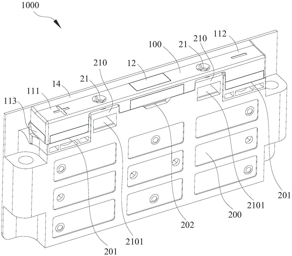
Referring to fig. 3 and 4, an embodiment of the present invention further provides a module end plate 1000, the module end plate 1000 is applied to a battery module, the module end plate 1000 includes an end plate body 200 and the protective structure 100 of any of the above embodiments, the end plate body 200 has an electrode mounting port 201 for mounting a positive terminal lead-out end and/or a negative terminal lead-out end of the battery module, that is, only one electrode mounting port 201 may be provided for mounting the positive terminal lead-out end or the negative terminal lead-out end of the battery module, the two electrode mounting ports 201 may be provided for mounting the positive terminal lead-out end and the negative terminal lead-out end of the battery module respectively, and the end plate body 200 further has an insertion mounting port 202 for mounting an insertion terminal of the battery module; the fixing structure 20 of the protection structure is connected to the end plate body 200, the electrode leading-out protection part 11 of the protection structure is covered on the electrode mounting opening 201, and the inserting protection part 12 of the protection structure is covered on the inserting mounting opening 202.
The embodiment of the utility model provides a module end plate 1000, owing to adopted foretell protective structure 100, can prevent effectively that external foreign matter from invading the positive pole of battery module and drawing forth the end, the negative pole draws forth the end, peg graft the end and lead to its impaired to can prevent that positive pole from drawing forth end and negative pole and drawing forth the junction of end and external connection spare, peg graft end and external plug connector junction receive the invasion of foreign matter such as condensation, water droplet and lead to appearing safety risks such as short circuit, can effectively improve the security of battery module and battery package.
In one embodiment, referring to fig. 3, the end plate body 200 has a snap-fit portion 210, and the fixing structure 20 is an elastic snap-fit portion 21 snap-fitted with the snap-fit portion 210; an open cavity 2101 is formed between the snap-fit portion 210 and the end plate body 200, the snap-fit portion 210 has a connection hole communicating with the open cavity 2101, the elastic snap-fit portion 21 is snap-fitted to the connection hole, and the snap-fit portion 210 may be a plate-shaped body or an arch-shaped body, but is not limited thereto. So set up, be convenient for convenient installation and dismantlement between protective structure 100 and the module end plate 1000, and be formed with opening chamber 2101 because of between block cooperation portion 210 and the end plate body 200, opening chamber 2101 is not linked together with the inside of battery module promptly, block cooperation portion 210 has the connecting hole that is linked together with opening chamber 2101, elasticity block portion 21 block in the connecting hole, when drop of water such as condensation drips on the protective structure body, and when infiltration elasticity block portion 21 and between the connecting hole, can flow to opening chamber 2101 along the connecting hole, flow to outside by opening chamber 2101 again, prevent that the drop of water from appearing the safety risk through electric connection position, can further improve the security.
Further, referring to fig. 3, a through hole penetrating through the electrode leading-out protection portion 11 and the elastic clamping portion 21 is formed on the protection structure body 100, and when droplets such as condensation drop on the protection structure body 10, the droplets can flow into the connection hole through the through hole on the protection structure body 10, flow to the opening cavity 2101 along the connection hole, and flow to the outside through the opening cavity 2101, so that the droplets are prevented from passing through the electrical connection portion to cause a safety risk.
The embodiment of the utility model provides a still provides a battery module, battery module include module shell and a plurality of electricity core, and electric core all sets up in the inside of module shell, and battery module has the positive pole and draws forth end, negative pole and draw forth end and the end of pegging graft, and battery module still includes the protective structure 100 of above-mentioned arbitrary embodiment, and protective structure 100 can set up and draw forth end, negative pole and draw forth end and the end of pegging graft in order to positive pole on the module shell and protect.
Because the embodiment of the utility model provides an foretell protective structure 100 has been adopted, therefore it has the technological effect that the technical scheme of above-mentioned protective structure 100 brought equally, can prevent effectively that external foreign matter from invading the positive pole of battery module and drawing forth the end, the negative pole is drawn forth the end, peg graft the end and lead to its impaired, and can prevent that the positive pole from drawing forth end and/or negative pole and drawing forth end and external connection spare junction, peg graft end and external plug connector junction receive the invasion of foreign matter such as condensation and lead to the safety risks such as short circuit appearing, can effectively improve the security of battery module and battery package.
In another embodiment, the battery module includes the module end plate 1000 of any of the above embodiments, and the module end plate 1000 may be an end plate constituting a module case. Since the module end plate 1000 is adopted, the module end plate also has the technical effects brought by the technical solution of the protection structure 10, and details are not described herein.
The embodiment of the utility model provides a still provide a battery package, battery package includes the battery module of above-mentioned arbitrary embodiment. The battery pack can further comprise a box body, and the battery module is arranged in the box body.
Because the embodiment of the utility model provides an adopted foretell battery module, therefore its technical effect that the technical scheme who has above-mentioned protective structure 100 equally brought can prevent that the positive pole from drawing forth end and negative pole and draw forth end and external connection spare junction, grafting end and external plug connector junction receive the invasion of foreign matters such as condensation and lead to the safety risks such as short circuit appearing, can effectively improve the security of battery package.
The embodiment of the utility model provides a still provide a vehicle, the vehicle includes foretell battery package.
Because the embodiment of the utility model provides an adopted foretell battery package, therefore its technical effect that the technical scheme who has above-mentioned protective structure 100 equally brought can prevent that the positive pole from drawing forth end and/or negative pole and draw forth end and external connection spare junction, grafting end and external plug connector junction receive the invasion of foreign matters such as condensation and lead to the safety risks such as short circuit appearing, can effectively improve the security of vehicle.
The above description is only exemplary of the present invention and should not be construed as limiting the present invention, and any modifications, equivalents and improvements made within the spirit and principles of the present invention are intended to be included within the scope of the present invention.