CN214898174U - Inner closed waterproof power switch - Google Patents
Inner closed waterproof power switch Download PDFInfo
- Publication number
- CN214898174U CN214898174U CN202121486813.8U CN202121486813U CN214898174U CN 214898174 U CN214898174 U CN 214898174U CN 202121486813 U CN202121486813 U CN 202121486813U CN 214898174 U CN214898174 U CN 214898174U
- Authority
- CN
- China
- Prior art keywords
- switch
- pressing rod
- sheet
- spring
- conductive
- Prior art date
- Legal status (The legal status is an assumption and is not a legal conclusion. Google has not performed a legal analysis and makes no representation as to the accuracy of the status listed.)
- Active
Links
- 230000003068 static effect Effects 0.000 claims abstract description 21
- 230000000712 assembly Effects 0.000 claims abstract description 8
- 238000000429 assembly Methods 0.000 claims abstract description 8
- XLYOFNOQVPJJNP-UHFFFAOYSA-N water Substances O XLYOFNOQVPJJNP-UHFFFAOYSA-N 0.000 claims description 10
- 229910001220 stainless steel Inorganic materials 0.000 claims description 6
- 239000010935 stainless steel Substances 0.000 claims description 6
- 230000007797 corrosion Effects 0.000 claims description 3
- 238000005260 corrosion Methods 0.000 claims description 3
- 239000013535 sea water Substances 0.000 claims description 3
- 229920001296 polysiloxane Polymers 0.000 claims 1
- 238000007789 sealing Methods 0.000 description 6
- VYPSYNLAJGMNEJ-UHFFFAOYSA-N Silicium dioxide Chemical compound O=[Si]=O VYPSYNLAJGMNEJ-UHFFFAOYSA-N 0.000 description 2
- 239000004020 conductor Substances 0.000 description 2
- 238000000034 method Methods 0.000 description 2
- 230000001681 protective effect Effects 0.000 description 2
- 239000000741 silica gel Substances 0.000 description 2
- 229910002027 silica gel Inorganic materials 0.000 description 2
- 238000010586 diagram Methods 0.000 description 1
- 230000005684 electric field Effects 0.000 description 1
- 239000000463 material Substances 0.000 description 1
- 230000007935 neutral effect Effects 0.000 description 1
- 239000004033 plastic Substances 0.000 description 1
- 239000007779 soft material Substances 0.000 description 1
Images



Landscapes
- Switch Cases, Indication, And Locking (AREA)
- Push-Button Switches (AREA)
Abstract
The utility model discloses an inner closed waterproof power switch, which comprises a switch shell, a press rod, a spring and a conductive component; the pressing rod and the spring are arranged in the switch shell; the pressing rod is of a step long-strip structure with wide bottom and narrow top and is positioned in the center of the switch shell, one end of the spring is clamped at the bottom of the pressing rod, the other end of the spring is fixed at the bottom of the switch shell, the other end of the pressing rod, which is far away from the spring, is connected with a pressing rod sleeve arranged outside the switch shell, and the pressing rod can be pushed down by pressing down the pressing rod sleeve; the two groups of conductive assemblies are respectively arranged in a cavity between the press rod and the switch shell, and each conductive assembly comprises a waterproof rubber sleeve, a conductive sheet static sheet, a conductive sheet moving sheet and two switch conductive sheets; the static conducting sheet and the moving conducting sheet are arranged in the waterproof rubber sleeve, a certain gap is reserved between the static conducting sheet and the moving conducting sheet in a natural state, and the static conducting sheet and the moving conducting sheet are respectively connected with a switch conducting sheet; four conducting strips in two sets of conducting assemblies constitute two pairs of contacts, carry out on-off control to live wire and zero line respectively to the switching of control switch.
Description
Technical Field
The utility model belongs to the technical field of electrical equipment, concretely relates to interior closed waterproof switch.
Background
In the electrical field, all electric equipment and electric products need to use a switch to complete the on-off of a power supply so as to ensure the safety of equipment and human bodies. Many locations also have to use power switches with water resistance. At present, all existing waterproof switches are externally closed, so that various accidents can be caused when the waterproof function of the existing waterproof switches is damaged particularly in deep water.
The prior art adopts a method of sealing the whole power switch in the aspect of water resistance. Such a method has a number of drawbacks. The switch is integrally sealed, so that the appearance of the product is enlarged, the application range of the product is greatly limited, and the switch can not be applied to small electric appliances, such as power sockets, power strip and other small electric appliances. Secondly, the external sealing body is easy to be damaged mechanically, so that the waterproof function of the product is lost. The waterproof switch is basically sealed by insulating soft materials such as rubber, plastic and the like, and the materials are easy to age and damage on the outside and lose the protection function.
Disclosure of Invention
To the weak point among the prior art, the utility model provides an interior closed waterproof switch for conductive parts is whole sealed and has waterproof function, has more the reliability at dampproofing, water proof spattering, mould proof.
In order to achieve the above purpose, the utility model discloses technical scheme as follows:
an inner closed waterproof power switch comprises a switch shell, a press rod, a spring and a conductive assembly; the pressing rod and the spring are arranged in the switch shell; the pressing rod is of a step long-strip structure with wide bottom and narrow top and is positioned in the center of the switch shell, one end of the spring is clamped at the bottom of the pressing rod, the other end of the spring is fixed at the bottom of the switch shell, the other end of the pressing rod, which is far away from the spring, is connected with a pressing rod sleeve arranged outside the switch shell, and the pressing rod can be pushed down by pressing down the pressing rod sleeve; the two groups of conductive assemblies are respectively arranged in a cavity between the press rod and the switch shell, and each conductive assembly comprises a waterproof rubber sleeve, a conductive sheet static sheet, a conductive sheet moving sheet and two switch conductive sheets; the conducting plate static sheet and the conducting plate moving sheet are arranged in the waterproof rubber sleeve, a certain gap is reserved between the conducting plate static sheet and the conducting plate moving sheet in a natural state, the conducting plate static sheet is arranged far away from the pressing rod 3, and the conducting plate moving sheet is arranged close to the pressing rod; the conducting plate static plate and the conducting plate moving plate are respectively connected with a switch conducting plate; four conducting strips in two sets of conducting assemblies constitute two pairs of contacts, carry out on-off control to live wire and zero line respectively to the switching of control switch.
Further, still include two bluff pieces, two the bluff piece sets up respectively according to between pole and the conductive component, and the bluff piece is the rectangular vertical rectangular of the slope of first half and the latter half respectively, and the slope of first half is rectangular to meet with according to the pole broadside.
Further, the guard plate is made of stainless steel.
Further, the spring is made of stainless steel, so that the switch has corrosion resistance.
Furthermore, the waterproof rubber sleeve is made of silica gel and can resist certain pressure, and can be used in water with the depth of more than 10 meters and seawater.
Further, still include the pilot lamp, the pilot lamp sets up at switch casing top, shows the switch break-make and can be waterproof.
Has the advantages that: the utility model changes the protection mode of the existing product, changes the external sealing into the internal sealing, and realizes that the switch can be used in water without any sealing outside; the waterproof performance is improved, the volume can be reduced, the reliability is greatly improved, and the blank of a small-volume inner-closed waterproof power switch is filled. Meanwhile, the conductive piece can be sealed in the switch, and the switch can be reliably used in water with the depth of more than 10 meters without electric leakage even if the outer shell of the switch is damaged.
Drawings
FIG. 1 is a connection diagram of the switch conducting strip of the present invention;
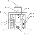
FIG. 2 is a schematic structural view showing the lifting state of the pressing rod of the present invention;
FIG. 3 is a schematic view of a partial structure of the pressing rod of the present invention;
fig. 4 is a top view of the present invention.
In the figure, 1-a pressing rod sleeve, 2-a switch shell, 3-a pressing rod, 4-a protective sheet, 5-a waterproof rubber sleeve, 6-a conductive sheet static sheet, 7-a spring, 8-a conductive sheet movable sheet and 9-an indicator light;
Lgo out、LInto、NGo out、NInto-a switch conducting strip outlet.
Detailed Description
The present invention is described below with reference to specific examples. It will be understood by those skilled in the art that these examples are for illustrative purposes only and are not intended to limit the scope of the present invention in any way.
An internally-closed waterproof power switch is shown in figures 1 to 4 and comprises a switch shell 2, a press rod 3, two protection sheets 4, a spring 7, an indicator light 9 and a conductive component; the pressing rod 3, the two guard plates 4 and the spring 7 are all arranged in the switch shell 2. The pressing rod 3 is of a step long-strip structure with a wide bottom and a narrow top, is located in the center of the switch shell 2, the bottom of the pressing rod is clamped with one end of the spring 7, the other end of the spring 7 is fixed at the bottom of the switch shell 2, the other end, far away from the spring 7, of the pressing rod 3 is connected with the pressing rod sleeve 1 arranged outside the switch shell 2, and the pressing rod 3 can be pushed down by pressing the pressing rod sleeve 1. Two protecting pieces 4 are arranged on two opposite sides of the pressing rod 3, the protecting pieces 4 are respectively an inclined strip of the upper half part and a vertical strip of the lower half part, and the inclined strip of the upper half part is connected with the wide side of the pressing rod 3. The two groups of conducting assemblies are respectively arranged in a cavity between the guard plate 4 and the switch shell 2, and each conducting assembly comprises a waterproof rubber sleeve 5, a conducting plate static plate 6, a conducting plate moving plate 8 and two switch conducting plates; the conducting plate static sheet 6 and the conducting plate moving sheet 8 are arranged in the waterproof rubber sleeve 5, a certain gap is reserved between the conducting plate static sheet 6 and the conducting plate moving sheet 8 in a natural state, the conducting plate static sheet 6 is arranged far away from the pressing rod 3, and the conducting plate moving sheet 8 is arranged close to the pressing rod 3; the conducting plate static plate 6 and the conducting plate moving plate 8 are respectively connected with a switch conducting plate; four conducting strips in the two groups of conducting assemblies form two pairs of contacts for respectively carrying out switch control on a live wire and a zero line; the indicator light 9 is arranged on the top of the switch shell 2 and displays the on-off state of the switch.
In this embodiment, the protective sheet 4 is made of stainless steel and is disposed between the push rod 3 and the waterproof rubber cover 5.
In this embodiment, the spring 7 is made of stainless steel and is disposed between the pressing rod 3 and the bottom of the switch housing 2, so that the switch has corrosion resistance.
In this embodiment, the waterproof rubber sleeve 6 is made of silica gel and can resist a certain pressure, and can be used in water of more than 10 meters and in seawater.
In this embodiment, the indicator lamp 9 can be waterproof.
The utility model discloses a theory of operation:
(1) as shown in fig. 1 and 2, there are four switch conducting strips, each having a contact, for switching the live and neutral conductors. The four conducting strips form two pairs of contacts, the AB contact controls a live wire L, the CD contact controls a zero line N, and the four contacts and the conducting strips are sealed in a waterproof rubber sleeve 5 and completely isolated from the outside, so that the conductor is waterproof in an inner sealing mode;
(2) as shown in fig. 2, when the push rod 3 of the switch is in a lifted state, two groups of contacts in the waterproof rubber sleeve 5 are separated, so that the live line L and the zero line N of the power supply are both cut off, and the switch is in a closed state;
(3) when the pressing rod sleeve 1 is pressed down, the pressing rod 3 moves downwards, and when the protruding part of the pressing rod 3 moves to the positions of the conducting plate static piece 6 and the conducting plate moving piece 8, the conducting component is pushed towards two sides, so that the contact A and the contact B of the conducting plate are connected, the contact C and the contact D are connected, and the switch is in an open state. The press rod of the switch has a self-locking function, and can keep self-locking when being opened or closed, namely, the switch is switched on once and then switched off once again.
Claims (6)
1. An inner closed waterproof power switch is characterized by comprising a switch shell, a pressing rod, a spring and a conductive assembly; the pressing rod and the spring are arranged in the switch shell; the pressing rod is of a step long-strip structure with wide bottom and narrow top and is positioned in the center of the switch shell, one end of the spring is clamped at the bottom of the pressing rod, the other end of the spring is fixed at the bottom of the switch shell, the other end of the pressing rod, which is far away from the spring, is connected with a pressing rod sleeve arranged outside the switch shell, and the pressing rod can be pushed down by pressing down the pressing rod sleeve; the two groups of conductive assemblies are respectively arranged in a cavity between the press rod and the switch shell, and each conductive assembly comprises a waterproof rubber sleeve, a conductive sheet static sheet, a conductive sheet moving sheet and two switch conductive sheets; the conducting plate static sheet and the conducting plate moving sheet are arranged in the waterproof rubber sleeve, a certain gap is reserved between the conducting plate static sheet and the conducting plate moving sheet in a natural state, the conducting plate static sheet is arranged far away from the pressing rod, and the conducting plate moving sheet is arranged close to the pressing rod; the conducting plate static plate and the conducting plate moving plate are respectively connected with a switch conducting plate; four conducting strips in two sets of conducting assemblies constitute two pairs of contacts, carry out on-off control to live wire and zero line respectively to the switching of control switch.
2. The internally-enclosed, waterproof power switch of claim 1, further comprising two guard plates, the two guard plates being respectively disposed between the pressing rod and the conductive member, the guard plates being an inclined strip of the upper half and a vertical strip of the lower half, the inclined strip of the upper half being connected to a broad side of the pressing rod.
3. The internally-enclosed, waterproof power switch of claim 2 wherein the guard plate is made of stainless steel.
4. The internally-enclosed, waterproof power switch of claim 1, wherein the spring is made of stainless steel to provide corrosion resistance to the switch.
5. The internally-enclosed, waterproof power switch of claim 1 wherein the waterproof grommet is made of silicone and is resistant to pressure, capable of use in water of 10 meters or more, and in seawater.
6. The internally-enclosed waterproof power switch of claim 1, further comprising an indicator light disposed on top of the switch housing to indicate on/off of the switch and to prevent water.
Priority Applications (1)
| Application Number | Priority Date | Filing Date | Title |
|---|---|---|---|
| CN202121486813.8U CN214898174U (en) | 2021-07-01 | 2021-07-01 | Inner closed waterproof power switch |
Applications Claiming Priority (1)
| Application Number | Priority Date | Filing Date | Title |
|---|---|---|---|
| CN202121486813.8U CN214898174U (en) | 2021-07-01 | 2021-07-01 | Inner closed waterproof power switch |
Publications (1)
| Publication Number | Publication Date |
|---|---|
| CN214898174U true CN214898174U (en) | 2021-11-26 |
Family
ID=78929317
Family Applications (1)
| Application Number | Title | Priority Date | Filing Date |
|---|---|---|---|
| CN202121486813.8U Active CN214898174U (en) | 2021-07-01 | 2021-07-01 | Inner closed waterproof power switch |
Country Status (1)
| Country | Link |
|---|---|
| CN (1) | CN214898174U (en) |
Cited By (1)
| Publication number | Priority date | Publication date | Assignee | Title |
|---|---|---|---|---|
| CN116759253A (en) * | 2023-08-18 | 2023-09-15 | 江苏中鹏电气有限公司 | Outdoor waterproof switch |
-
2021
- 2021-07-01 CN CN202121486813.8U patent/CN214898174U/en active Active
Cited By (2)
| Publication number | Priority date | Publication date | Assignee | Title |
|---|---|---|---|---|
| CN116759253A (en) * | 2023-08-18 | 2023-09-15 | 江苏中鹏电气有限公司 | Outdoor waterproof switch |
| CN116759253B (en) * | 2023-08-18 | 2023-10-20 | 江苏中鹏电气有限公司 | Outdoor waterproof switch |
Similar Documents
| Publication | Publication Date | Title |
|---|---|---|
| CN206282807U (en) | Switch disconnector | |
| JPS6452355A (en) | Two-dimensional electric conductor | |
| US11721931B2 (en) | Safety socket module, and power strip and mobile cable reel comprising same | |
| ATE469452T1 (en) | THREE-POSITION GROUND SWITCH | |
| CN103198970B (en) | Vacuum envelope with double-fracture structure | |
| SG154375A1 (en) | Vacuum switchgear and a method of diagnosing vacuum pressure thereof | |
| CN103326192A (en) | Safety socket | |
| CN202205926U (en) | Electric connector for inflatable-type high-voltage electric appliance | |
| CN213520424U (en) | Three-hole safety socket | |
| CN210272927U (en) | Safe waterproof socket | |
| CN203352037U (en) | Outdoor high-voltage solid insulated column switch platform | |
| CN204333433U (en) | Waterproof socket | |
| WO2009076975A1 (en) | Medium-voltage switchgear assembly | |
| CN214706397U (en) | Waterproof mechanical switch | |
| CN206148702U (en) | A power plug that can be stored | |
| CN108493019A (en) | A kind of safety switch of the explosion-proof high reliability of water proof and dust proof | |
| CN213584336U (en) | Lock control component | |
| CN118197860A (en) | A contact structure and a contactor | |
| CN209471889U (en) | A kind of small size temperature controller | |
| CN205810713U (en) | A kind of RCCB N level system | |
| CN205230943U (en) | Multi -functional magnetic -type switch | |
| CN204045481U (en) | A kind of 110kV isolating switch | |
| TW373207B (en) | Vacuum valve and vacuum circuit breaker utilizing said vacuum valve | |
| CN206532726U (en) | A grounding switch structure applied to cooker | |
| CN213459561U (en) | Outdoor high-voltage three-station vacuum circuit breaker |
Legal Events
| Date | Code | Title | Description |
|---|---|---|---|
| GR01 | Patent grant | ||
| GR01 | Patent grant |