Disclosure of Invention
The water boiler convenient for sewage discharge is provided in the embodiment and used for solving the problem that the water boiler is inconvenient to move in the prior art.
According to one aspect of the application, the water boiler convenient for sewage discharge comprises a water boiler box body, a supporting mechanism, a first motor, a fixed table, a partition plate, a water outlet pipe and a fixed shell, wherein the supporting mechanism, the first motor, the fixed table, the partition plate, the water outlet pipe and the fixed shell are arranged on one side of the water boiler box body, the fixed table is fixedly connected to the bottom of the water boiler box body, the water outlet pipe penetrates through and is fixedly connected to the right side of the water boiler box body, the top of the water boiler box body is connected with a box door through a hinge, the partition plate is arranged inside the water boiler box body, a plurality of first guide pipes penetrate through the bottom of the partition plate, the fixed shell is fixedly connected to the bottom of the first guide pipes, the water boiler inner container is fixedly connected to the fixed shell, the supporting mechanism comprises a second threaded rod, the second threaded rod is rotatably connected to the inside of the fixed table, first bevel gears are fixedly connected to the left side and the right side of the second threaded rod, one side of the bottom of the first bevel gears is meshed with a second bevel gear, the bottom of the second bevel gear is fixedly connected with a sleeve rod, the outer side of the sleeve rod is fixedly connected with a fixed plate, and the bottom of the sleeve rod is in threaded connection with a first threaded rod.
Further, a heat insulation layer is fixedly connected inside the water boiler box body, and a water boiler inner container is fixedly connected inside the heat insulation layer.
Furthermore, a first motor is fixedly connected to the left side of the water boiler box body, an output end of the first motor is fixedly connected with a rotating shaft, a plurality of scraping sheets are fixedly connected to the surface of the rotating shaft, and the scraping sheets are uniformly distributed on the surface of the rotating shaft.
Further, a filter screen is arranged in the fixed shell, a sealing plate is fixedly connected to one side of the filter screen, and the sealing plate is connected with the water boiler box in a penetrating mode.
Furthermore, a second gear is fixedly connected to a middle shaft of the second threaded rod, the bottom of the second gear is meshed with the first gear, one side of the first gear is fixedly connected with the output end of a second motor, and the bottom of the second motor is fixedly connected to a mounting groove formed in the fixed table.
Further, first threaded rod bottom fixed connection connecting plate, connecting plate bottom symmetry fixed connection advancing wheel, the connecting plate left and right sides sliding connection fixed station, the inside spacing groove of seting up with the connecting plate adaptation of fixed station.
Through the above-mentioned embodiment of this application, adopted supporting mechanism, solved the problem of being convenient for to remove, guaranteed the commonality of device simultaneously.
Drawings
In order to more clearly illustrate the embodiments of the present application or the technical solutions in the prior art, the drawings needed to be used in the description of the embodiments or the prior art will be briefly introduced below, and it is obvious that the drawings in the following description are only some embodiments of the present application, and it is obvious for those skilled in the art that other drawings can be obtained according to the drawings without inventive exercise.
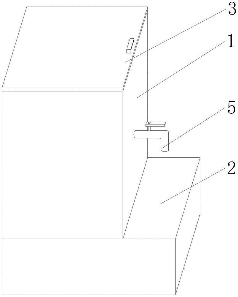
FIG. 1 is a schematic overall perspective view of an embodiment of the present application;
FIG. 2 is a schematic diagram of the overall internal structure of an embodiment of the present application;
fig. 3 is an enlarged schematic view of a structure shown in fig. 2 according to an embodiment of the present disclosure.
In the figure: 1. the water boiler comprises a water boiler box body, 2, a fixed platform, 3, a box cover, 4, a first threaded rod, 5, a water outlet pipe, 6, a sleeve rod, 7, a heat insulation layer, 8, a water boiler inner container, 9, a first motor, 10, a sealing plug, 11, a scraping piece, 12, a rotating shaft, 13, a partition plate, 14, a first guide pipe, 15, a fixed plate, 16, a fixed shell, 17, a filter screen, 18, a second guide pipe, 19, a mounting groove, 20, a second motor, 21, a first gear, 22, a second gear, 23, a traveling wheel, 24, a connecting plate, 25, a limiting groove, 26, a second threaded rod, 27, a first bevel gear, 28, a second bevel gear, 29 and a sealing plate.
Detailed Description
In order to make the technical solutions better understood by those skilled in the art, the technical solutions in the embodiments of the present application will be clearly and completely described below with reference to the drawings in the embodiments of the present application, and it is obvious that the described embodiments are only partial embodiments of the present application, but not all embodiments. All other embodiments, which can be derived by a person skilled in the art from the embodiments given herein without making any creative effort, shall fall within the protection scope of the present application.
It should be noted that the terms "first," "second," and the like in the description and claims of this application and in the drawings described above are used for distinguishing between similar elements and not necessarily for describing a particular sequential or chronological order. It should be understood that the data so used may be interchanged under appropriate circumstances such that embodiments of the application described herein may be used. Furthermore, the terms "comprises," "comprising," and "having," and any variations thereof, are intended to cover a non-exclusive inclusion, such that a process, method, system, article, or apparatus that comprises a list of steps or elements is not necessarily limited to those steps or elements expressly listed, but may include other steps or elements not expressly listed or inherent to such process, method, article, or apparatus.
In this application, the terms "upper", "lower", "left", "right", "front", "rear", "top", "bottom", "inner", "outer", "middle", "vertical", "horizontal", "lateral", "longitudinal", and the like indicate orientations or positional relationships based on the orientations or positional relationships shown in the drawings. These terms are used primarily to better describe the present application and its embodiments, and are not used to limit the indicated devices, elements or components to a particular orientation or to be constructed and operated in a particular orientation.
Moreover, some of the above terms may be used to indicate other meanings besides the orientation or positional relationship, for example, the term "on" may also be used to indicate some kind of attachment or connection relationship in some cases. The specific meaning of these terms in this application will be understood by those of ordinary skill in the art as appropriate.
Furthermore, the terms "mounted," "disposed," "provided," "connected," and "sleeved" are to be construed broadly. For example, it may be a fixed connection, a removable connection, or a unitary construction; can be a mechanical connection, or an electrical connection; may be directly connected, or indirectly connected through intervening media, or may be in internal communication between two devices, elements or components. The specific meaning of the above terms in the present application can be understood by those of ordinary skill in the art as appropriate.
It should be noted that the embodiments and features of the embodiments in the present application may be combined with each other without conflict. The present application will be described in detail below with reference to the embodiments with reference to the attached drawings.
The supporting mechanism in this embodiment may be suitable for supporting various moving carts, for example, in this embodiment, a garbage cart convenient for cleaning is provided, and the supporting mechanism in this embodiment may be used to support the garbage cart.
The utility model provides a garbage truck convenient to clearance, includes locomotive, carriage, wheel, carriage door, adjusting device and cleaning device, the right side swing joint of locomotive has the carriage, the equal movable mounting in bottom of carriage and locomotive has the wheel, the right-hand member movable mounting in carriage has the carriage door, adjusting device is installed on the left of the top in the carriage door, cleaning device is installed to left side and bottom in the carriage. Adjusting device includes first motor, first motor fixed mounting is on the carriage top right side, the output swing joint of first motor has first gear, the right side meshing of first gear has the second gear, the positive fixed surface of second gear is connected with the movable block. Cleaning device includes the second motor, second motor fixed mounting is in carriage bottom left side, the output swing joint of second motor has the lead screw, threaded connection has the screw thread piece on the lead screw, the middle part swing joint of screw thread piece has the spout, the first scraper blade of top fixedly connected with of screw thread piece, the equal movable mounting in both ends of lead screw has the bearing housing, the right side fixedly connected with of screw thread piece prevents the jam plate, left side inner wall top fixed mounting has electric telescopic handle in the carriage, electric telescopic handle's flexible pot head is equipped with the spring, electric telescopic handle's flexible end swing joint has the second scraper blade. Furthermore, the bottom end of the movable block is fixedly connected with a carriage door, and the top end of the movable block is movably connected with the top end of the right side in the carriage through a pin shaft. Furthermore, the first gear and the second gear are both half-tooth gears, and the rear surface of the second gear is movably connected with a pin shaft. Furthermore, the second motor is fixedly installed on the left side of the bottom end in the carriage, and the rotating direction of the second motor is matched with the direction of the thread block. Further, the length of the screw rod is matched with that of the carriage, and the thread block penetrates through the sliding groove and extends to the outside of the sliding groove. Furthermore, the anti-blocking plate is fixedly arranged on the right side of the thread block, the anti-blocking plate is matched with the groove width of the sliding groove, and the thickness of the anti-blocking plate is matched with the groove depth of the sliding groove. Furthermore, electric telescopic handle's flexible stroke and the interior high phase-match of carriage, and the left side swing joint of second scraper blade has the interior left side inner wall of carriage.
Of course, the support mechanism of the embodiment can also be applied to the support of various water boilers. Here, description is not repeated, and the water boiler according to the embodiment of the present application is described below.
Referring to fig. 1-3, the water boiler convenient for sewage discharge comprises a water boiler box body 1, a supporting mechanism, a first motor 9, a fixed platform 2, a partition plate 13, a water outlet pipe 5 and a fixed shell 16, wherein the supporting mechanism, the first motor 9, the fixed platform 2, the partition plate 13, the water outlet pipe 5 and the fixed shell 16 are arranged on one side of the water boiler box body 1, the fixed platform 2 is fixedly connected to the bottom of the water boiler box body 1, the water outlet pipe 5 penetrates through and is fixedly connected to the right side of the water boiler box body 1, the top of the water boiler box body 1 is connected with a boiler door 3 through a hinge, the partition plate 13 is arranged in the water boiler box body 1, the bottom of the partition plate 13 is connected with a plurality of first guide pipes 14 in a penetrating manner, the bottom of the first guide pipes 14 is connected with the fixed shell 16 in a penetrating manner, the fixed shell 16 is fixedly connected with a boiler liner 8, the supporting mechanism comprises a second threaded rod 26, the second threaded rod 26 is rotatably connected with the inside the fixed platform 2, the first bevel gear 27 is fixedly connected to the left side and the right side of the second threaded rod 26, one side of the bottom of the first bevel gear 27 is engaged with a second bevel gear 28, the bottom of the second bevel gear 28 is fixedly connected with a sleeve rod 6, the outer side of the sleeve rod 6 is fixedly connected with a fixing plate 15, and the bottom of the sleeve rod 6 is in threaded connection with a first threaded rod 4.
A heat insulation layer 7 is fixedly connected inside the water boiler box body 1, and a water boiler inner container 8 is fixedly connected inside the heat insulation layer 7; the left side of the water boiler box body 1 is fixedly connected with a first motor 9, the output end of the first motor 9 is fixedly connected with a rotating shaft 12, the surface of the rotating shaft 12 is fixedly connected with a plurality of scraping blades 11, and the scraping blades 11 are uniformly distributed on the surface of the rotating shaft 12; a filter screen 17 is arranged in the fixed shell 16, a sealing plate 29 is fixedly connected to one side of the filter screen 17, and the sealing plate 29 is connected with the water boiler box body 1 in a penetrating manner; a second gear 22 is fixedly connected to the middle shaft of the second threaded rod 26, the bottom of the second gear 22 is engaged with a first gear 21, one side of the first gear 21 is fixedly connected with the output end of a second motor 20, and the bottom of the second motor 20 is fixedly connected to a mounting groove 19 formed in the fixed table 2; the bottom of the first threaded rod 4 is fixedly connected with a connecting plate 24, the bottom of the connecting plate 24 is symmetrically and fixedly connected with traveling wheels 23, the left side and the right side of the connecting plate 24 are slidably connected with a fixed table 2, and a limit groove 25 matched with the connecting plate 24 is formed in the fixed table 2.
The utility model discloses when using, the electrical components that appear in this application all external intercommunication power and control switch when using, dirt and deposit can appear in long-term use back boiler bottom, when blowdown to the boiler, at first start first motor 9, first motor 9 output drives the axis of rotation 12 rather than the rigid coupling and rotates, axis of rotation 12 drives the doctor-bar 11 rather than the rigid coupling and rotates, doctor-bar 11 rotates along with axis of rotation 12 and scrapes the dirt of boiler bottom, then open the control valve of first pipe 14, the dirt gets into in set casing 16, waste water is discharged from second pipe 18 after filter screen 17 filters, when clearing up filter screen 17, outside pulling closing plate 29, clear up it, the efficiency of blowdown has greatly been improved; when the water boiler box body 1 needs to be moved, the second motor 20 is started, the output end of the second motor 20 drives the first gear 21 fixedly connected with the second motor to rotate, the first gear 21 drives the second threaded rod 26 to rotate through the second gear 22 meshed with the first gear, the second threaded rod 26 drives the first bevel gears 27 fixedly connected with the two sides to rotate, the first bevel gears 27 drive the socket-joint rods 6 to rotate through the second bevel gears 28 meshed with the first bevel gears 27, the socket-joint rods 6 drive the first threaded rods 4 with the bottoms in threaded connection with the first threaded rods to move downwards, the first threaded rods 4 drive the connecting plates 24 fixedly connected with the bottoms to move downwards, the connecting plates 24 drive the traveling wheels 23 fixedly connected with the bottoms to move downwards in the limiting grooves 25, and the traveling wheels 23 support the water boiler box body 1, so that the movement of the water boiler is realized, and the structural rationality is embodied.
The application has the advantages that:
1. in order to improve the efficiency of pollution discharge, when the water boiler is subjected to pollution discharge, a first motor is started, the output end of the first motor drives a rotating shaft fixedly connected with the first motor to rotate, the rotating shaft drives a scraping blade fixedly connected with the rotating shaft to rotate, the scraping blade scrapes dirt at the bottom of the water boiler along with the rotation of the rotating shaft, then a control valve of a first guide pipe is opened, the dirt enters a fixed shell, waste water is discharged from a second guide pipe after being filtered by a filter screen, and when the filter screen is cleaned, a sealing plate is pulled outwards to clean the waste water, so that the efficiency of pollution discharge is greatly improved;
2. this application is rational in infrastructure, when needs move the water boiler box, the output of second motor drives the first gear rotation rather than the rigid coupling, first gear drives the second threaded rod through rather than the second gear of meshing and rotates, the first bevel gear of second threaded rod drive both sides rigid coupling rotates, first bevel gear drives the rotation of bell and spigot joint pole through rather than the second conical gear of meshing, the bell and spigot joint pole drives the first threaded rod of bottom rather than threaded connection and moves down, first threaded rod drives the connecting plate of bottom rigid coupling and moves down, the connecting plate drives the running wheel of bottom rigid coupling and moves down at the spacing inslot, the running wheel supports the water boiler box, the removal of boiler has been realized, the rationality of structure has been embodied.
It is well within the skill of those in the art to implement, without undue experimentation, the present application is not directed to software and process improvements, as they relate to circuits and electronic components and modules.
The above description is only a preferred embodiment of the present application and is not intended to limit the present application, and various modifications and changes may be made by those skilled in the art. Any modification, equivalent replacement, improvement and the like made within the spirit and principle of the present application shall be included in the protection scope of the present application.