Pressure reducing valve
Technical Field
The utility model relates to a bathroom field specifically relates to a relief pressure valve.
Background
The pressure reducing valve of the existing waterway pipeline is usually installed at the outer side of the pipeline, and the structure of the pressure reducing valve is generally the structure of the pressure reducing valve disclosed in patent CN 105003702B. The pressure reducing valve structure is externally connected to the pipeline. However, this pressure reducing valve has a problem that the inside thereof is provided with a vent hole communicating with the outside atmosphere. When the internal sealing is poor, water flows out from the vent hole of the pressure reducing valve, and the use environment is affected. And the pressure reducing valve has more parts, complex structure and high production cost.
Disclosure of Invention
The utility model aims at providing an improved relief pressure valve to solve above-mentioned problem. Therefore, the utility model discloses a specific technical scheme as follows:
a pressure reducing valve can comprise a valve cover, a valve seat, a valve core and a spring, wherein the valve cover and the valve seat are mounted together in a sealing mode to form a mounting cavity and provided with a water inlet communicated with the mounting cavity in a fluid mode, the valve seat is provided with a water outlet communicated with the mounting cavity in the fluid mode, the valve core is provided with a water passing hole and mounted in the mounting cavity through the spring, the water passing hole is communicated with the water outlet, the valve core is switched between a first position and a second position under the action of water inlet pressure and the spring, in the first position, the valve core opens a water passing channel between the valve core and the inner wall of the valve cover, and in the second position, the valve core closes the water passing channel between the valve core and the inner wall of the valve cover.
Further, the valve core comprises a plugging portion with a larger outer diameter and a columnar portion with a smaller outer diameter, the valve seat comprises an inner ring portion and an outer ring portion, the water outlet is arranged between the inner ring portion and the outer ring portion, the columnar portion is inserted into the inner ring portion, the spring is sleeved on the inner ring portion in a sleeved mode, one end of the spring abuts against the plugging portion, the other end of the spring abuts against the valve seat, the plugging portion and the outer ring portion are at least partially overlapped, and the water passing hole is formed in the plugging portion.
Furthermore, one end of the blocking part close to the water inlet is a groove, and the cross-sectional area of the water passing hole is 1/20-1/10 of the cross-sectional area of the groove.
Further, the middle of the groove is provided with a bulge, and the water through hole is formed between the bulge and the wall of the groove.
Furthermore, the number of the water through holes is 1-4.
Furthermore, a sealing ring mounting groove is formed in the valve seat.
Furthermore, a plurality of axially extending reinforcing ribs are arranged on the inner wall of the water inlet.
Further, the valve cover, the valve seat and the valve core are formed by injection molding of ABS materials.
The utility model adopts the above technical scheme, the beneficial effect who has is: the utility model discloses simple structure, the part is few, convenient assembling, low in production cost to there is not the air vent, avoids leaking and influences the environment.
Drawings
To further illustrate the embodiments, the present invention provides the accompanying drawings. The accompanying drawings, which are incorporated in and constitute a part of this disclosure, illustrate embodiments of the invention and, together with the description, serve to explain the principles of the embodiments. With these references, one of ordinary skill in the art will appreciate other possible embodiments and advantages of the present invention. Elements in the figures are not drawn to scale and like reference numerals are generally used to indicate like elements.
Fig. 1 is a perspective view of a pressure reducing valve according to an embodiment of the present invention;
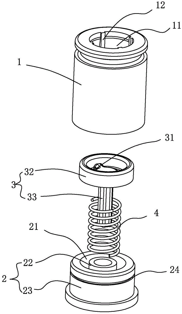
FIG. 2 is an exploded view of the pressure relief valve shown in FIG. 1;
FIG. 3 is a schematic illustration of the water circuit with the valve spool in the first position;
fig. 4 is a schematic illustration of the water path when the valve spool is in the second position.
Detailed Description
The present invention will now be further described with reference to the accompanying drawings and detailed description.
As shown in fig. 1 to 4, a pressure reducing valve may include a valve housing 1, a valve seat 2, a valve core 3, and a spring 4, wherein the valve housing 1 and the valve seat 2 are sealingly mounted together to form a mounting cavity and have a water inlet 11 in fluid communication with the mounting cavity. The valve seat 2 has an outlet 21 in fluid communication with the mounting chamber. The valve core 3 is provided with a water through hole 31 and is movably arranged in the mounting cavity through a spring 4. The water through hole 31 is communicated with the water outlet 21. The valve core 3 is switched between a first position and a second position under the action of the water inlet pressure and the spring 4. Specifically, in the second position (i.e., when the water inlet pressure is low), the valve element 3 opens the water passage C between the valve element 3 and the inner wall of the valve housing 1, and water is normally supplied, see fig. 3; and when the valve core 3 is at the first position (i.e. when the water inlet pressure is higher), the water passing channel C between the valve core 3 and the inner wall of the valve cover 1 is closed, water only passes through the water passing hole 31, the flow rate is reduced, and the purpose of pressure reduction is achieved, see fig. 4.
In the present embodiment, the valve body 3 includes a stopper portion 32 having a larger outer diameter and a columnar portion 33 having a smaller outer diameter. The water flow hole 31 is provided in the blocking portion 32. The end (hereinafter referred to as the upper end) of the blocking part 32 near the water inlet 11 is a groove, and the cross-sectional area of the water passing hole 31 is 1/20-1/10 of the cross-sectional area of the groove. Therefore, the valve body 3 can be moved toward the outlet port 21 by the water pressure. The middle of the groove is provided with a projection 321, and the water through holes 31 are arranged between the projection 321 and the wall of the groove. The number and size of the water through holes 31 are set according to the requirement, and the number of the water through holes 31 can be 1-4 in general. Of course, the upper end of the blocking portion 32 may be a flat surface. The valve seat 2 comprises an inner ring part 22 and an outer ring part 23 which are coaxial, and the water outlet 21 is arranged between the inner ring part 22 and the outer ring part 23. The blocking portion 32 at least partially overlaps the outer ring portion 23 to block a water passage C between the valve element 3 and the inner wall of the valve housing 1. When the valve element 3 is mounted, the column portion 33 is inserted into the inner ring portion 22, and the spring 4 is fitted around the inner ring portion 22, with one end abutting against the stopper portion 32 and the other end abutting against the valve seat 3. When the valve core 3 moves towards the water outlet 21 under the action of water pressure, the spring 4 is compressed; when the water pressure is reduced, the valve core 3 moves towards the water inlet under the action of the restoring force of the spring 4, and a water passing channel C between the valve core 3 and the inner wall of the valve cover 1 is opened.
To facilitate the seal ring installation, a seal ring installation groove 24 is provided on the outer wall of the valve seat 2 (specifically, the outer ring portion 23).
Preferably, be equipped with many axially extending strengthening rib 12 on the inner wall of water inlet 11 to improve its intensity, damage when avoiding the installation to dismantle, increase of service life.
The valve cover 1, the valve seat 2 and the valve core 3 may be made of a metallic material or a non-metallic material. Preferably, the valve cover 1, the valve seat 2 and the valve core 3 are injection molded by ABS material, and the production cost is low.
The assembly process and the working principle of the present invention will be briefly described below. During assembly, the spring 4 is sleeved on the inner ring part 22, the sealing ring is sleeved on the sealing ring mounting groove 24, the valve core 3 is inserted into the inner ring part 22, and finally the valve cover 1 is sleeved on the valve seat 2. Therefore, the pressure reducing valve is simple in structure, few in parts and convenient to assemble. In the initial state, when the valve core 3 is at the first position, water flows in from the water inlet 11 of the valve cover 1, flows out through a large gap between the valve core 3 and the inner wall of the valve cover 1, and finally flows out from the water outlet 21 of the valve seat 2, and the water flow path is shown by an arrow in fig. 3; when the water pressure at the inlet is gradually increased, the valve core 3 moves towards the water outlet 21 and compresses the spring 4, and reaches the second position, namely, one end (the blocking part 32) of the valve core 3 abuts against one end (the outer ring part 23) of the valve seat 2, so that the water passing channel C between the valve core 3 and the inner wall of the valve cover 1 is closed, at the moment, water can only flow out through the water passing hole 31 of the valve core 3, and therefore the pressure reducing and throttling effects are achieved, and the water flowing path is shown by an arrow in fig. 4. When the inlet water pressure is reduced, the valve core 3 is reset under the action of the spring force, and the water passing channel C between the valve core 3 and the inner wall of the valve cover 1 is restored (opened) again, as shown in fig. 3.
While the invention has been particularly shown and described with reference to a preferred embodiment, it will be understood by those skilled in the art that various changes in form and detail may be made therein without departing from the spirit and scope of the invention as defined by the appended claims.