Roadbed construction protection device
Technical Field
The utility model relates to a construction protector relates to protector technical field, concretely relates to road bed construction protector.
Background
The roadbed is a foundation of a track or a road surface and is a geotechnical structure formed by excavation or filling, the roadbed mainly has the functions of providing necessary conditions for track or road surface laying and train or traveling operation, bearing static load and dynamic load of the track and rolling stock or road surface and traffic load, and simultaneously transmitting and diffusing the load to the deep part of the foundation, and the roadbed must ensure the required elevation of a line on a longitudinal section.
The following problems exist in the prior art:
1. due to the integration of the design structure of the protective guard protective device, the protective guard protective device is inconvenient to disassemble and assemble, thereby causing certain difficulty to equipment transportation, further increasing the transportation cost, increasing the roadbed construction cost and influencing the practicability of the equipment;
2. because the roadbed construction is generally outdoor, the stability of the bottom of the protective guard protective device is poor, equipment is easy to overturn under the action of strong wind, and the life safety of workers on the roadbed construction cannot be guaranteed.
SUMMERY OF THE UTILITY MODEL
The technical problem to be solved by the utility model is to provide a roadbed construction protection device, wherein one purpose is to provide a function of convenient disassembly, and solve the problem that the equipment is inconvenient to disassemble, so that certain difficulty is caused in transportation; the other purpose is in order to have fixed function, makes things convenient for equipment to increase stability, is favorable to equipment guarantee constructor's life safety, and it is relatively poor to have solved rail guard protector bottom stability for equipment overturns easily, leads to equipment to lose the effect of protection, and constructor's life safety can't obtain the problem of guaranteeing.
In order to solve the technical problem, the utility model discloses the technical scheme who adopts is:
the utility model provides a road bed construction protector, includes the rail guard frame, the inside fixed mounting of rail guard frame has the rail guard post, the top fixed mounting of rail guard frame has signal lamp device, signal lamp device's top fixed mounting has the flashing lamp, the both sides fixed mounting of rail guard frame has the support column, the side fixed mounting of support column has the connecting block, the bottom fixed mounting of support column has fixing device, fixing device's bottom fixed mounting has the bottom plate.
The utility model discloses technical scheme's further improvement lies in: the connecting groove is formed in the connecting block, the mounting hole is formed in the side face of the connecting block, and the mounting bolt is fixedly mounted in the mounting hole.
The utility model discloses technical scheme's further improvement lies in: a clamping block is fixedly mounted on the other side of the supporting column, and a connecting hole is formed in the side face of the clamping block.
The utility model discloses technical scheme's further improvement lies in: the bottom fixed mounting of flashing lamp has the spliced pole, the bottom fixed mounting of spliced pole has the connecting plate, the top threaded connection of connecting plate has fixing bolt.
The utility model discloses technical scheme's further improvement lies in: the fixing device is characterized in that a fixing block is fixedly mounted at the top of the fixing device, a first bolt is in threaded connection with the side face of the fixing block, a fixing column is fixedly connected to the bottom of the first bolt, a fixed bottom block is fixedly mounted at the bottom of the fixing column, and a second bolt is in threaded connection with the top of the fixed bottom block.
The utility model discloses technical scheme's further improvement lies in: the surface of the guardrail column is fixedly provided with a reflective strip, and the bottom of the guardrail frame is fixedly provided with a reflective block.
The utility model discloses technical scheme's further improvement lies in: the inner part of the bottom plate is fixedly provided with a pressing plate, the bottom of the pressing plate is fixedly provided with a compression spring, and the bottom of the compression spring is fixedly provided with a lower pressing block.
Owing to adopted above-mentioned technical scheme, the utility model discloses relative prior art, the technological progress who gains is:
1. the utility model provides a road bed construction protector, through the erection joint piece, the spread groove, the mounting hole, construction bolt, fixture block and connecting hole mutually support, one side through the rail guard frame is connected with the another side of second rail guard frame, then by the fixture block joint to the inside of spread groove, then by construction bolt threaded connection inside mounting hole and connecting hole again, make through construction bolt fixed connection fixture block and connecting block, thereby convenient installation and dismantlement, and then make things convenient for equipment to carry out convenient transportation, be favorable to saving extra freight, reduce the cost of transportation.
2. The utility model provides a road bed construction protector, through the installation fixed block, a bolt, the fixed column, the fixed bottom piece, No. two bolts, the bottom plate, the clamp plate, compression spring and lower briquetting mutually support, through the fixed block by a bolt threaded connection on the support column, then fixed block fixed mounting fixed column, then pass through No. two bolt threaded connection on the clamp plate by the fixed bottom piece again, make fixed column fixed connection on the clamp plate, thereby make the stability that increases the support column bottom, make things convenient for equipment to increase stability, be favorable to increasing the protectiveness of equipment.
Drawings
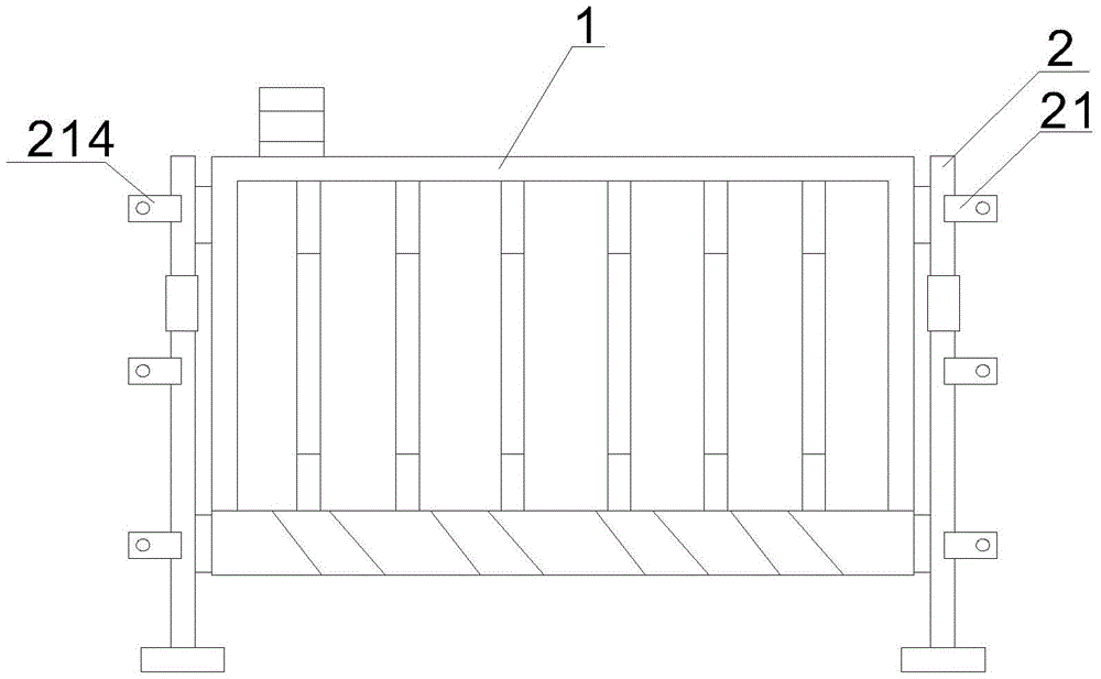
Fig. 1 is a schematic structural view of the present invention;
fig. 2 is a front view structural diagram of the protective guard frame of the present invention;
FIG. 3 is a schematic structural view of a signal lamp apparatus according to the present invention;
FIG. 4 is a schematic view of the connecting block structure of the present invention;
fig. 5 is a schematic structural view of the fixing device of the present invention;
fig. 6 is a schematic view of the sectional structure of the bottom plate of the present invention.
In the figure: 1. a guard rail frame; 10. a light reflecting block; 11. a guardrail post; 111. a light-reflecting strip; 12. a signal lamp device; 122. connecting columns; 123. a connecting plate; 124. fixing the bolt; 121. a flashing light; 2. a support pillar; 21. connecting blocks; 211. connecting grooves; 212. mounting holes; 213. installing a bolt; 214. a clamping block; 215. connecting holes; 22. a fixing device; 221. a fixed block; 222. a first bolt; 223. fixing a column; 224. fixing the bottom block; 225. a second bolt; 23. a base plate; 24. pressing a plate; 25. a compression spring; 26. and (7) pressing the blocks.
Detailed Description
The present invention will be described in further detail with reference to the following examples:
example 1
As shown in fig. 1-6, the utility model provides a road bed construction protector, including rail guard frame 1, rail guard frame 1's inside fixed mounting has rail post 11, rail guard frame 1's top fixed mounting has signal lamp device 12, signal lamp device 12's top fixed mounting has flashing lamp 121, rail guard frame 1's both sides fixed mounting has support column 2, support column 2's side fixed mounting has connecting block 21, support column 2's bottom fixed mounting has fixing device 22, fixing device 22's bottom fixed mounting has bottom plate 23, connecting groove 211 has been seted up to connecting block 21's inside, mounting hole 212 has been seted up to the side of connecting block 21, the inside fixed mounting of mounting hole 212 has mounting bolt 213, support column 2's opposite side fixed mounting has fixture block 214, connecting hole 215 has been seted up to fixture block 214's side.
In this embodiment, one side of the guard rail frame 1 is connected to the other side of the second guard rail frame 1, the fixture block 214 is clamped into the connecting groove 211, and the mounting bolt 213 is screwed into the mounting hole 212 and the connecting hole 215, so that the fixture block 214 and the connecting block 21 are fixedly connected by the mounting bolt 213, and therefore the mounting and dismounting are convenient, the transportation of the device is convenient, the additional transportation cost is saved, and the transportation cost is reduced.
Example 2
As shown in fig. 1-6, on the basis of embodiment 1, the utility model provides a technical solution: the top of the fixing device 22 is fixedly provided with a fixing block 221, the side surface of the fixing block 221 is in threaded connection with a first bolt 222, the bottom of the first bolt 222 is fixedly connected with a fixing column 223, the bottom of the fixing column 223 is fixedly provided with a fixing bottom block 224, the top of the fixing bottom block 224 is in threaded connection with a second bolt 225, the inside of the bottom plate 23 is fixedly provided with a pressing plate 24, the bottom of the pressing plate 24 is fixedly provided with a compression spring 25, the bottom of the compression spring 25 is fixedly provided with a lower pressing block 26, the fixing block 221 is connected to the supporting column 2 through the first bolt 222, then the fixing block 221 is fixedly provided with the fixing column 223, and then the fixing bottom block 224 is screwed on the pressure plate 24 through the second bolt 225, so that the fixing column 223 is fixedly connected on the pressure plate 24, thereby make the stability that increases 2 bottoms of support column, make things convenient for equipment to increase stability, be favorable to increasing the protectiveness of equipment.
Example 3
As shown in fig. 1-6, on the basis of embodiment 1, the utility model provides a technical solution: preferably, the surface of the guardrail post 11 is fixedly provided with the light reflecting strip 111, the bottom of the guardrail frame 1 is fixedly provided with the light reflecting block 10, the bottom of the flashing lamp 121 is fixedly provided with the connecting post 122, the bottom of the connecting post 122 is fixedly provided with the connecting plate 123, the top of the connecting plate 123 is in threaded connection with the fixing bolt 124, the flashing lamp 121 is installed at the top of the guardrail frame 1, so that passersby can be conveniently reminded, then the light reflecting strip 111 is installed by the guardrail post 11, then the light reflecting block 10 is installed at the bottom of the guardrail frame 1, so that light of vehicles coming and going is reflected at night, thereby conveniently reminding the vehicles, and the life safety of constructors is guaranteed.
The working principle of the roadbed construction protection device is described in detail below.
As shown in fig. 1 to 6, one side of a guard rail frame 1 is connected with the other side of a second guard rail frame 1, and then the fixture block 214 is clamped inside the connecting groove 211, and then the mounting bolt 213 is screwed inside the mounting hole 212 and the connecting hole 215, so that the fixture block 214 and the connecting block 21 are fixedly connected through the mounting bolt 213, thereby facilitating the mounting and dismounting;
as shown in fig. 1-6, the fixing block 221 is connected to the supporting column 2 through a first bolt 222, then the fixing block 221 is fixedly provided with the fixing column 223, and then the fixing bottom block 224 is connected to the pressing plate 24 through a second bolt 225 by threads, so that the fixing column 223 is fixedly connected to the pressing plate 24, and therefore the stability of the bottom of the supporting column 2 is improved, and the stability of the equipment is improved conveniently.
The present invention has been described in detail with reference to the above general description, but it will be apparent to one of ordinary skill in the art that modifications and improvements can be made to the invention. Therefore, modifications or improvements without departing from the spirit of the invention are within the scope of the invention.