CN214885293U - A bracket for civil engineering construction - Google Patents

A bracket for civil engineering construction Download PDF

Info

Publication number
CN214885293U
CN214885293U CN202120875745.8U CN202120875745U CN214885293U CN 214885293 U CN214885293 U CN 214885293U CN 202120875745 U CN202120875745 U CN 202120875745U CN 214885293 U CN214885293 U CN 214885293U
Authority
CN
China
Prior art keywords
rod
base
groove
support
civil engineering
Prior art date
Legal status (The legal status is an assumption and is not a legal conclusion. Google has not performed a legal analysis and makes no representation as to the accuracy of the status listed.)
Expired - Fee Related
Application number
CN202120875745.8U
Other languages
Chinese (zh)
Inventor
陈大鹏
余海飞
龚元龙
Current Assignee (The listed assignees may be inaccurate. Google has not performed a legal analysis and makes no representation or warranty as to the accuracy of the list.)
Zunyi Normal University
Original Assignee
Zunyi Normal University
Priority date (The priority date is an assumption and is not a legal conclusion. Google has not performed a legal analysis and makes no representation as to the accuracy of the date listed.)
Filing date
Publication date
Application filed by Zunyi Normal University filed Critical Zunyi Normal University
Priority to CN202120875745.8U priority Critical patent/CN214885293U/en
Application granted granted Critical
Publication of CN214885293U publication Critical patent/CN214885293U/en
Expired - Fee Related legal-status Critical Current
Anticipated expiration legal-status Critical

Links

Images

Landscapes

  • Bridges Or Land Bridges (AREA)

Abstract

本实用新型公开了一种用于土木工程建筑施工的支架,涉及土木工程技术领域,本实用新型中,通过设置的防护机构可根据工人的身高进行调节,能够对不同身高的工人起到很好的保护效果,提高了支架的适用性,解决了现有的护栏高度无法调节导致的保护作用小以及实用性较差的问题,通过设置的升降机构可在不同高度进行施工,使施工更加方便,有利于工人的使用,通过设置的调节机构能够对滚轮的位置进行调节,避免使用时滚轮承受较大压力,容易造成滚轮损坏,延长了滚轮的使用寿命,同时能够提高支架放置时的稳定性。

Figure 202120875745

The utility model discloses a support for civil engineering construction, which relates to the technical field of civil engineering. In the utility model, a protective mechanism provided in the utility model can be adjusted according to the height of workers, which can play a good role for workers with different heights. The protection effect improves the applicability of the bracket, and solves the problems of small protection effect and poor practicability caused by the inability to adjust the height of the existing guardrail. It is beneficial to the use of workers, and the position of the roller can be adjusted through the set adjustment mechanism, so as to avoid the roller from being subjected to large pressure during use, which is easy to cause damage to the roller, prolong the service life of the roller, and improve the stability of the bracket when placed.

Figure 202120875745

Description

Support for civil engineering building construction
Technical Field
The utility model relates to a civil engineering technical field especially relates to a support for civil engineering construction.
Background
The building construction refers to production activities in the engineering construction implementation stage, is the construction process of various buildings, and also can be a process of changing various lines on a design drawing into a real object at a specified place, and comprises foundation engineering construction, main structure construction, roofing engineering construction, decoration engineering construction and the like, wherein the construction operation place is called a building construction site or a construction site, also called a construction site, and the civil engineering building construction support is an auxiliary support frame for civil engineering construction.
The prior patent (publication number: CN212836608U) provides a bracket for civil engineering construction, which solves the problems that the bracket is used for construction in civil engineering construction, the traditional civil engineering construction bracket is easy to shake when lifting, and the stability of the bracket is poor when the bracket is placed in a region with large wind power or a hollow road surface;
the civil engineering construction support has the following disadvantages when in use: guardrail height can't be adjusted, can not play fine guard action to the higher workman of height, and the practicality is relatively poor, and the gyro wheel bears great pressure when using, causes the gyro wheel to damage easily, has shortened gyro wheel life, and for this reason, we provide a support for civil engineering building construction and solve above-mentioned problem.
SUMMERY OF THE UTILITY MODEL
The utility model provides a support for civil engineering construction has solved the high unable regulation of guardrail, can not play fine guard action to the higher workman of height, and the practicality is relatively poor, and the gyro wheel bears great pressure when using, causes the gyro wheel to damage easily, has shortened gyro wheel life's technical problem.
In order to solve the technical problem, the utility model provides a support for civil engineering construction, which comprises a base, a support column, a sliding sleeve, an operation platform, a protection mechanism, a lifting mechanism and an adjusting mechanism;
the quantity of support column is four, four the support column is fixed mounting respectively in the four corners department at base top, the sliding sleeve slip cap is established on the support column, operation platform and sliding sleeve fixed connection, the last protection machanism who is used for protecting operating personnel construction safety that is equipped with of operation platform, be equipped with the elevating system who is used for adjusting operation platform height between base and the operation platform, the bottom of base is seted up flutedly, adjustment mechanism sets up the inside at the recess.
Preferably, protection machanism includes first fender rod, second fender rod, protection frame and fixing bolt, the quantity of first fender rod is a plurality of, and is a plurality of first fender rod is rectangle array fixed mounting at operation platform's top, second fender rod sliding connection is in the inside of first fender rod, protection frame fixed mounting is located at the top of second fender rod threaded connection has fixing bolt on the first fender rod of operation platform top four corners department, fixing bolt's one end extends to the inside of first fender rod and offsets with the outer wall of second fender rod.
Preferably, the lifting mechanism comprises a bidirectional screw rod, a nut, a limit block, a slide rod, a slide block, a connecting rod and a driving motor, the inside of the base is provided with an installation groove, the bidirectional screw rod is rotationally connected inside the installation groove of the base, the number of the nuts is two, the two nuts are both in threaded connection with the bidirectional screw rod, the limiting block is fixedly arranged at the bottom of the nut, a limiting groove for the limiting block to slide is formed in the base, the sliding rod is fixedly arranged at the bottom of the operating platform, the number of the sliding blocks is two, the two sliding blocks are connected on the sliding rod in a sliding way, the bottom of the sliding block is rotationally connected with a connecting rod, one end of the connecting rod, which is far away from the sliding block, extends into the mounting groove and is rotatably connected with the top of the nut, the driving motor is fixedly installed on the right side of the base, and the right end of the bidirectional screw rod is fixedly connected with the driving end of the driving motor.
Preferably, a plurality of annular grooves are formed in the inner wall of the sliding block, balls are embedded in the annular grooves, and the balls are abutted to the outer wall of the sliding rod.
Preferably, one side fixed mounting of base has the installation shell, driving motor fixed mounting is in the inside of installation shell.
Preferably, the adjusting mechanism comprises a mounting plate, a guide block, a guide groove, a roller, a rotating rod, a threaded sleeve, a threaded rod, a driven bevel gear and a driving bevel gear, the mounting plate is connected inside the groove in a sliding way, the guide blocks are fixedly arranged at two sides of the mounting plate, the base is internally provided with a guide groove for the guide block to slide, the number of the rollers is four, the four rollers are respectively and fixedly arranged at the four corners of the bottom of the mounting plate, the rotating rod is rotatably connected inside the groove, the threaded sleeve is fixedly inserted in the center of the mounting plate, the threaded rod is connected inside the threaded sleeve in a threaded manner, the top end of the threaded rod is rotationally connected with the inner top wall of the groove, the driven bevel gear is fixedly arranged at the upper part of the threaded rod, the driving bevel gear is fixedly arranged at the right end of the rotating rod and is in meshed connection with the driven bevel gear.
Preferably, the inner top wall of the groove is fixedly provided with an installation block, and the rotating rod is rotatably connected inside the installation block.
Preferably, the left end of bull stick extends to the left side of base and fixedly connected with rotates the hand wheel, it is located the base outside to rotate the hand wheel.
Compared with the prior art, the utility model provides a pair of have following beneficial effect:
1. the utility model discloses in, can adjust according to workman's height through the protection machanism who sets up, can play fine protection effect to the workman of different heights, improved the suitability of support.
2. The utility model discloses in, can adjust the position of gyro wheel through the adjustment mechanism who sets up, the gyro wheel bears great pressure when avoiding using, causes the gyro wheel to damage easily, has prolonged the life of gyro wheel, can improve the stability when the support is placed simultaneously.
Drawings
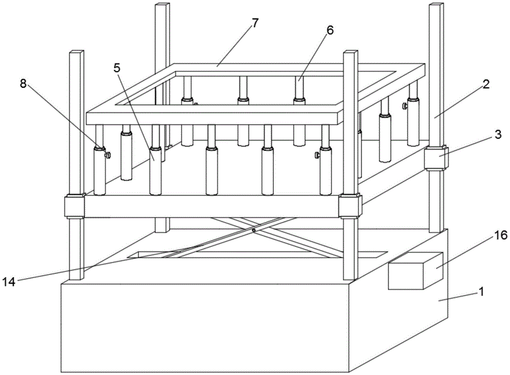
Fig. 1 is a schematic structural view of a support for civil engineering construction;
FIG. 2 is a schematic view of a front cross-sectional structure of a support for civil engineering construction;
FIG. 3 is a schematic view of a connection structure of a slide bar and a slide block in a bracket for civil engineering construction;
fig. 4 is an enlarged view of a structure at a in fig. 2.
Reference numbers in the figures: 1. a base; 2. a support pillar; 3. a sliding sleeve; 4. an operating platform; 5. a first guard bar; 6. a second guard bar; 7. a protective frame; 8. fixing the bolt; 9. a bidirectional screw rod; 10. a nut; 11. a limiting block; 12. a slide bar; 13. a slider; 14. a connecting rod; 15. a drive motor; 16. mounting a shell; 17. mounting a plate; 18. a guide block; 19. a guide groove; 20. a roller; 21. mounting blocks; 22. a rotating rod; 23. rotating a hand wheel; 24. a threaded sleeve; 25. a threaded rod; 26. a driven bevel gear; 27. a drive bevel gear; 28. and a ball.
Detailed Description
The technical solutions in the embodiments of the present invention will be clearly and completely described below with reference to the drawings in the embodiments of the present invention, and it is obvious that the described embodiments are only some embodiments of the present invention, not all embodiments; based on the embodiments in the present invention, all other embodiments obtained by a person skilled in the art without creative work belong to the protection scope of the present invention.
Embodiment one, given by fig. 1-4, a support for civil engineering construction comprises a base 1, a support column 2, a sliding sleeve 3, an operating platform 4, a protection mechanism, a lifting mechanism and an adjusting mechanism;
the quantity of support column 2 is four, four support column 2 respectively fixed mounting are in the four corners department at base 1 top, 3 sliding sleeve of sliding sleeve establish on support column 2, operating platform 4 and 3 fixed connection of sliding sleeve, operating platform 4 is last to be equipped with and to be used for protecting operating personnel safety in construction's safeguard mechanism, be equipped with the elevating system who is used for adjusting operating platform 4 height between base 1 and the operating platform 4, the recess has been seted up to base 1's bottom, adjustment mechanism sets up the inside at the recess.
Embodiment two, on the basis of embodiment one, protection machanism includes first fender rod 5, second fender rod 6, protective frame 7 and fixing bolt 8, the quantity of first fender rod 5 is a plurality of, a plurality of first fender rods 5 are rectangle array fixed mounting at operation platform 4's top, 6 sliding connection of second fender rod is in the inside of first fender rod 5, 7 fixed mounting at the top of second fender rod 6 of protective frame, threaded connection has fixing bolt 8 on the first fender rod 5 that is located 4 top four corners departments of operation platform, fixing bolt 8's one end extends to the inside of first fender rod 5 and offsets with the outer wall of second fender rod 6, can adjust according to workman's protection machanism through the protection machanism that sets up, can play fine protection effect to the workman of different heights, the suitability of support has been improved.
Third embodiment, on the basis of the first embodiment, the lifting mechanism includes a bidirectional screw rod 9, a nut 10, a limiting block 11, a sliding rod 12, a sliding block 13, a connecting rod 14 and a driving motor 15, a mounting groove is formed in the base 1, the bidirectional screw rod 9 is rotatably connected to the inside of the mounting groove of the base 1, the number of the nuts 10 is two, two nuts 10 are both in threaded connection with the bidirectional screw rod 9, the limiting block 11 is fixedly mounted at the bottom of the nut 10, a limiting groove for the limiting block 11 to slide is formed in the base 1, the sliding rod 12 is fixedly mounted at the bottom of the operating platform 4, the number of the sliding block 13 is two, two sliding blocks 13 are both in sliding connection with the sliding rod 12, the bottom of the sliding block 13 is rotatably connected with the connecting rod 14, one end of the connecting rod 14, which is far away from the sliding block 13, extends to the inside of the mounting groove and is rotatably connected with the top of the nut 10, the driving motor 15 is fixedly mounted at the right side of the base 1, the right end of the bidirectional screw rod 9 is fixedly connected with the driving end of the driving motor 15, and construction can be carried out at different heights through the arranged lifting mechanism, so that construction is more convenient, and the use of workers is facilitated.
Fourth embodiment, on the basis of third embodiment, seted up a plurality of ring channels on the inner wall of slider 13, the ball 28 has been inlayed in the inside of ring channel, and ball 28 offsets with the outer wall of slide bar 12, can play fine guide effect to the slip of slider 13 through the ball 28 that sets up, avoids slider 13 to take place the offset when sliding, and ball 28 takes place to rotate when slider 13 slides simultaneously and reduces the sliding friction power, makes slider 13 slide more convenient.
Fifth embodiment, on the basis of third embodiment, one side fixed mounting of base 1 has installation shell 16, and driving motor 15 fixed mounting has made things convenient for driving motor 15's installation in the inside of installation shell 16 through installation shell 16, can play fine protection effect to driving motor 15 simultaneously.
Sixth embodiment, on the basis of the first embodiment, the adjusting mechanism includes a mounting plate 17, a guide block 18, a guide groove 19, rollers 20, a rotating rod 22, a threaded sleeve 24, a threaded rod 25, a driven bevel gear 26 and a driving bevel gear 27, the mounting plate 17 is slidably connected inside the groove, the guide block 18 is fixedly installed at two sides of the mounting plate 17, the base 1 is internally provided with the guide groove 19 for the guide block 18 to slide, the number of the rollers 20 is four, the four rollers 20 are respectively and fixedly installed at four corners of the bottom of the mounting plate 17, the rotating rod 22 is rotatably connected inside the groove, the threaded sleeve 24 is fixedly inserted in the center of the mounting plate 17, the threaded rod 25 is threadedly connected inside the threaded sleeve 24, the top end of the threaded rod 25 is rotatably connected with the inner top wall of the groove, the driven bevel gear 26 is fixedly installed at the upper portion of the threaded rod 25, the driving bevel gear 27 is fixedly installed at the right end of the rotating rod 22, the driving bevel gear 27 is meshed with the driven bevel gear 26, the position of the roller 20 can be adjusted through the adjusting mechanism, the roller 20 bears large pressure when the adjusting mechanism is used, the roller 20 is damaged easily, the service life of the roller 20 is prolonged, and meanwhile the stability of the support when the support is placed can be improved.
Seventh embodiment, on the basis of sixth embodiment, fixed mounting has installation piece 21 on the interior roof of recess, and the bull stick 22 rotates and connects in the inside of installation piece 21, makes the bull stick 22 rotate more stably through the installation piece 21 that sets up.
Eight embodiment, on the basis of six embodiments, the left end of bull stick 22 extends to the left side of base 1 and fixedly connected with rotates hand wheel 23, rotates hand wheel 23 and is located base 1 outside, makes things convenient for operating personnel to rotate bull stick 22 through the rotation hand wheel 23 that sets up, need not to adjust with the help of the instrument, and it is more convenient to use.
In this embodiment: the drive motor 15 is of type YC 7124.
The working principle is as follows:
when the higher workman of height is under construction:
the first step is as follows: a worker stands on the operating platform 4, the four fixing bolts 8 are unscrewed, the fixing bolts 8 are separated from the second protection rod 6, the second protection rod 6 can slide upwards or downwards in the first protection rod 5 at the moment, the protection frame 7 is pulled to move upwards, the second protection rod 6 slides upwards, when the height of the protection frame 7 can protect workers with higher height, the four fixing bolts 8 are screwed to enable the fixing bolts 8 to be tightly abutted against the outer wall of the second protection rod 6, and the adjusted fixing can be realized to avoid the second protection rod 6 from automatically moving when in use;
the second step is that: the driving motor 15 is controlled to be started, the bidirectional screw rod 9 is driven to rotate through the driving motor 15, the two nuts 10 are driven to synchronously and relatively move through the bidirectional screw rod 9, the connecting rod 14 is driven to move through the nuts 10, the two sliding blocks 13 are driven to relatively slide on the sliding rod 12 through the connecting rod 14, the operating platform 4 can be pushed to move upwards, and workers can be pushed to a construction site.
When the bracket is used:
the first step is as follows: the rotating hand wheel 23 is rotated to drive the rotating rod 22 to rotate, the rotating rod 22 drives the driving bevel gear 27 to rotate, the driving bevel gear 27 is meshed with the driven bevel gear 26 to drive the threaded rod 25 to rotate, the threaded sleeve 24 is driven to move downwards through the threaded meshing of the threaded rod 25 and the threaded sleeve 24, the mounting plate 17 is driven to move downwards through the threaded sleeve 24, the mounting plate 17 drives the roller 20 to move downwards, and when the roller 20 is in contact with the ground, the base 1 is pushed to move;
the second step is that: after moving to appointed construction site, the contra-rotation rotates hand wheel 23, can stimulate mounting panel 17 to move upwards through the cooperation of thread bush 24, threaded rod 25, driven bevel gear 26 and drive bevel gear 27, and then make gyro wheel 20 retract to the inside of recess, the bottom of base 1 has increased the area of contact with ground with the ground contact this moment makes the support can more stable placing in the work progress, gyro wheel 20 retracts to the inside of recess simultaneously, avoid gyro wheel 20 to bear great pressure when using, cause the problem that gyro wheel 20 damaged easily, the life of gyro wheel 20 has been prolonged.
It is noted that, herein, relational terms such as first and second, and the like may be used solely to distinguish one entity or action from another entity or action without necessarily requiring or implying any actual such relationship or order between such entities or actions. Also, the terms "comprises," "comprising," or any other variation thereof, are intended to cover a non-exclusive inclusion, such that a process, method, article, or apparatus that comprises a list of elements does not include only those elements but may include other elements not expressly listed or inherent to such process, method, article, or apparatus.
Although embodiments of the present invention have been shown and described, it will be appreciated by those skilled in the art that changes, modifications, substitutions and alterations can be made in these embodiments without departing from the principles and spirit of the invention, the scope of which is defined in the appended claims and their equivalents.

Claims (8)

1.一种用于土木工程建筑施工的支架,其特征在于,包括底座(1)、支撑柱(2)、滑套(3)、操作平台(4)、防护机构、升降机构和调节机构;1. A support for civil engineering construction, characterized in that it comprises a base (1), a support column (2), a sliding sleeve (3), an operating platform (4), a protection mechanism, a lifting mechanism and an adjusting mechanism; 所述支撑柱(2)的数量为四个,四个所述支撑柱(2)分别固定安装在底座(1)顶部的四角处,所述滑套(3)滑动套设在支撑柱(2)上,所述操作平台(4)与滑套(3)固定连接,所述操作平台(4)上设有用于保护操作人员施工安全的防护机构,所述底座(1)和操作平台(4)之间设有用于调节操作平台(4)高度的升降机构,所述底座(1)的底部开设有凹槽,所述调节机构设置在凹槽的内部。The number of the support columns (2) is four, the four support columns (2) are respectively fixedly installed at the four corners of the top of the base (1), and the sliding sleeves (3) are slidably sleeved on the support columns (2). ), the operating platform (4) is fixedly connected with the sliding sleeve (3), the operating platform (4) is provided with a protective mechanism for protecting the operator's construction safety, the base (1) and the operating platform (4) ) is provided with a lifting mechanism for adjusting the height of the operating platform (4), the bottom of the base (1) is provided with a groove, and the adjusting mechanism is arranged inside the groove. 2.根据权利要求1所述的一种用于土木工程建筑施工的支架,其特征在于,所述防护机构包括第一防护杆(5)、第二防护杆(6)、防护框(7)和固定螺栓(8),所述第一防护杆(5)的数量为多个,多个所述第一防护杆(5)呈矩形阵列固定安装在操作平台(4)的顶部,所述第二防护杆(6)滑动连接在第一防护杆(5)的内部,所述防护框(7)固定安装在第二防护杆(6)的顶部,位于所述操作平台(4)顶部四角处的第一防护杆(5)上螺纹连接有固定螺栓(8),所述固定螺栓(8)的一端延伸至第一防护杆(5)的内部且与第二防护杆(6)的外壁相抵。2. A support for civil engineering construction according to claim 1, characterized in that the protection mechanism comprises a first protection rod (5), a second protection rod (6), a protection frame (7) and fixing bolts (8), the number of the first protection rods (5) is multiple, and the plurality of the first protection rods (5) are fixedly installed on the top of the operation platform (4) in a rectangular array, and the Two protective rods (6) are slidably connected to the inside of the first protective rod (5). A fixing bolt (8) is threadedly connected to the first protection rod (5), and one end of the fixing bolt (8) extends to the inside of the first protection rod (5) and abuts against the outer wall of the second protection rod (6). . 3.根据权利要求1所述的一种用于土木工程建筑施工的支架,其特征在于,所述升降机构包括双向丝杆(9)、丝母(10)、限位块(11)、滑杆(12)、滑块(13)、连接杆(14)和驱动电机(15),所述底座(1)的内部开设有安装槽,所述双向丝杆(9)转动连接在底座(1)安装槽的内部,所述丝母(10)的数量为两个,两个所述丝母(10)均螺纹连接在双向丝杆(9)上,所述限位块(11)固定安装在丝母(10)的底部,所述底座(1)的内部开设有供限位块(11)滑动的限位槽,所述滑杆(12)固定安装在操作平台(4)的底部,所述滑块(13)的数量为两个,两个所述滑块(13)均滑动连接在滑杆(12)上,所述滑块(13)的底部转动连接有连接杆(14),所述连接杆(14)远离滑块(13)的一端延伸至安装槽的内部且与丝母(10)的顶部转动连接,所述驱动电机(15)固定安装在底座(1)的右侧,所述双向丝杆(9)的右端与驱动电机(15)的驱动端固定连接。3. A support for civil engineering construction according to claim 1, wherein the lifting mechanism comprises a bidirectional screw (9), a screw nut (10), a limit block (11), a sliding A rod (12), a slider (13), a connecting rod (14) and a drive motor (15), a mounting groove is provided inside the base (1), and the two-way screw (9) is rotatably connected to the base (1). ) inside the installation groove, the number of the nut (10) is two, the two nut (10) are both threadedly connected to the two-way screw (9), and the limit block (11) is fixedly installed At the bottom of the nut (10), a limit groove for the limit block (11) to slide is opened inside the base (1), and the sliding rod (12) is fixedly installed on the bottom of the operation platform (4), The number of the sliding blocks (13) is two, the two sliding blocks (13) are both slidably connected to the sliding rod (12), and the bottom of the sliding block (13) is rotatably connected with a connecting rod (14) , the end of the connecting rod (14) away from the slider (13) extends to the inside of the installation slot and is rotatably connected with the top of the nut (10), and the driving motor (15) is fixedly installed on the right side of the base (1). On the side, the right end of the two-way screw (9) is fixedly connected with the driving end of the driving motor (15). 4.根据权利要求3所述的一种用于土木工程建筑施工的支架,其特征在于,所述滑块(13)的内壁上开设有多个环形槽,所述环形槽的内部嵌设有滚珠(28),所述滚珠(28)与滑杆(12)的外壁相抵。4. A support for civil engineering construction according to claim 3, characterized in that a plurality of annular grooves are formed on the inner wall of the slider (13), and the inside of the annular groove is embedded with Balls (28), the balls (28) abut against the outer wall of the sliding rod (12). 5.根据权利要求3所述的一种用于土木工程建筑施工的支架,其特征在于,所述底座(1)的一侧固定安装有安装壳(16),所述驱动电机(15)固定安装在安装壳(16)的内部。5. A support for civil engineering construction according to claim 3, wherein a mounting shell (16) is fixedly installed on one side of the base (1), and the drive motor (15) is fixed Installed inside the mounting shell (16). 6.根据权利要求1所述的一种用于土木工程建筑施工的支架,其特征在于,所述调节机构包括安装板(17)、导向块(18)、导向槽(19)、滚轮(20)、转杆(22)、螺纹套(24)、螺纹杆(25)、从动锥齿轮(26)和主动锥齿轮(27),所述安装板(17)滑动连接在凹槽内部,所述导向块(18)固定安装在安装板(17)两侧,所述底座(1)的内部开设有供导向块(18)滑动的导向槽(19),所述滚轮(20)的数量为四个,四个所述滚轮(20)分别固定安装在安装板(17)底部的四角处,所述转杆(22)转动连接在凹槽内部,所述螺纹套(24)固定插接在安装板(17)的中心处,所述螺纹杆(25)螺纹连接在螺纹套(24)的内部,且所述螺纹杆(25)的顶端与凹槽的内顶壁转动连接,所述从动锥齿轮(26)固定安装在螺纹杆(25)上部,所述主动锥齿轮(27)固定安装在转杆(22)的右端,所述主动锥齿轮(27)与从动锥齿轮(26)啮合连接。6. A support for civil engineering construction according to claim 1, characterized in that the adjustment mechanism comprises a mounting plate (17), a guide block (18), a guide groove (19), a roller (20) ), rotating rod (22), threaded sleeve (24), threaded rod (25), driven bevel gear (26) and driving bevel gear (27), the mounting plate (17) is slidably connected inside the groove, so The guide block (18) is fixedly installed on both sides of the mounting plate (17), the interior of the base (1) is provided with a guide groove (19) for the guide block (18) to slide, and the number of the rollers (20) is Four, the four rollers (20) are respectively fixed and installed at the four corners of the bottom of the mounting plate (17), the rotating rod (22) is rotatably connected inside the groove, and the threaded sleeve (24) is fixedly inserted in the groove. At the center of the mounting plate (17), the threaded rod (25) is threadedly connected to the inside of the threaded sleeve (24), and the top end of the threaded rod (25) is rotatably connected to the inner top wall of the groove. The driving bevel gear (26) is fixedly mounted on the upper part of the threaded rod (25), the driving bevel gear (27) is fixedly mounted on the right end of the rotating rod (22), the driving bevel gear (27) and the driven bevel gear (26) ) engaged connection. 7.根据权利要求6所述的一种用于土木工程建筑施工的支架,其特征在于,所述凹槽的内顶壁上固定安装有安装块(21),所述转杆(22)转动连接在安装块(21)的内部。7 . The support for civil engineering construction according to claim 6 , wherein a mounting block ( 21 ) is fixedly installed on the inner top wall of the groove, and the rotating rod ( 22 ) rotates. 8 . Connected inside the mounting block (21). 8.根据权利要求6所述的一种用于土木工程建筑施工的支架,其特征在于,所述转杆(22)的左端延伸至底座(1)的左侧且固定连接有转动手轮(23),所述转动手轮(23)位于底座(1)外部。8. A support for civil engineering construction according to claim 6, wherein the left end of the rotating rod (22) extends to the left side of the base (1) and is fixedly connected with a rotating handwheel ( 23), the rotating handwheel (23) is located outside the base (1).
CN202120875745.8U 2021-04-26 2021-04-26 A bracket for civil engineering construction Expired - Fee Related CN214885293U (en)

Priority Applications (1)

Application Number Priority Date Filing Date Title
CN202120875745.8U CN214885293U (en) 2021-04-26 2021-04-26 A bracket for civil engineering construction

Applications Claiming Priority (1)

Application Number Priority Date Filing Date Title
CN202120875745.8U CN214885293U (en) 2021-04-26 2021-04-26 A bracket for civil engineering construction

Publications (1)

Publication Number Publication Date
CN214885293U true CN214885293U (en) 2021-11-26

Family

ID=78888836

Family Applications (1)

Application Number Title Priority Date Filing Date
CN202120875745.8U Expired - Fee Related CN214885293U (en) 2021-04-26 2021-04-26 A bracket for civil engineering construction

Country Status (1)

Country Link
CN (1) CN214885293U (en)

Cited By (4)

* Cited by examiner, † Cited by third party
Publication number Priority date Publication date Assignee Title
CN114197893A (en) * 2021-12-17 2022-03-18 中建八局第四建设有限公司 Portable interlayer curtain wall dotting positioning device
CN114856145A (en) * 2022-05-25 2022-08-05 陕西建工集团股份有限公司 Support for civil engineering
CN114962892A (en) * 2022-05-27 2022-08-30 河南众惠工程设计有限公司 A support device for civil engineering
CN116591442A (en) * 2023-05-04 2023-08-15 黄诚 Lifting platform for building construction

Cited By (6)

* Cited by examiner, † Cited by third party
Publication number Priority date Publication date Assignee Title
CN114197893A (en) * 2021-12-17 2022-03-18 中建八局第四建设有限公司 Portable interlayer curtain wall dotting positioning device
CN114856145A (en) * 2022-05-25 2022-08-05 陕西建工集团股份有限公司 Support for civil engineering
CN114856145B (en) * 2022-05-25 2024-01-16 陕西建工集团股份有限公司 Support for civil engineering
CN114962892A (en) * 2022-05-27 2022-08-30 河南众惠工程设计有限公司 A support device for civil engineering
CN114962892B (en) * 2022-05-27 2024-07-19 河南众惠工程设计有限公司 A support device for civil engineering
CN116591442A (en) * 2023-05-04 2023-08-15 黄诚 Lifting platform for building construction

Similar Documents

Publication Publication Date Title
CN112707349A (en) Guide rail scissor type aerial work platform
CN211499909U (en) Support bracket for constructional engineering
CN113089479A (en) Municipal construction decorates light-duty operation car with outer hanging guardrail
CN212583204U (en) A kind of auxiliary dismantling equipment for construction engineering scaffolding
CN111375625B (en) A kind of steel structure building solid waste recycling and processing method
CN210369814U (en) Multifunctional building construction platform convenient to remove
CN210713907U (en) Protection device for construction safety
CN115432640A (en) Municipal administration tube-well construction auxiliary device
CN210508131U (en) Wall type guardrail handrail
CN208137379U (en) Novel building ergonomic support device
CN217602009U (en) Safety platform for construction
CN218758614U (en) Scaffold convenient to dismantle
CN218268126U (en) Multifunctional monitoring equipment
CN213710293U (en) Construction platform with safety protection function for building construction
CN210263832U (en) Movable cantilever platform
CN215443005U (en) Height-adjustable scaffold
CN215254715U (en) Bearing structure for construction
CN221321677U (en) Support for building engineering
CN215949115U (en) Construction protective guard for constructional engineering
CN213774837U (en) Rail guard for construction
CN115478669A (en) Lifting device for building engineering construction
CN113175195A (en) Shaft overlap joint operation platform with safety protection
CN222066090U (en) A construction scaffold for building construction
CN222140636U (en) A scaffolding for construction engineering
CN223523401U (en) An adjustable work platform

Legal Events

Date Code Title Description
GR01 Patent grant
GR01 Patent grant
CF01 Termination of patent right due to non-payment of annual fee

Granted publication date: 20211126

CF01 Termination of patent right due to non-payment of annual fee