Assembled building decorative plate
Technical Field
The utility model belongs to the technical field of the building decorative panel, in particular to pin-connected panel building decorative panel.
Background
The present assembled decorative board for building is made up by using wood core board, veneer board, decorative panel, density board, integrated material, shaving board, fire-resisting board, gypsum board, PVC board, aluminium gusset plate, aluminium-plastic board and three-dimensional board as main raw material through the processes of laying or coating them on the surface of building, and combining them into one body, so that it is an important material basis for building decoration engineering.
Although the existing assembled decorative plate can meet the basic requirements of decoration, when a certain decorative plate is damaged in the subsequent use process after the assembly is finished, the existing assembled decorative plate cannot be conveniently disassembled and replaced.
SUMMERY OF THE UTILITY MODEL
In view of this, the utility model provides a to the not enough of prior art, provide a pin-connected panel building decorative panel, not only can splice the installation at the in-process of installation, but also can dismantle the change to the decorative panel that takes place the damage at the in-process of follow-up use.
In order to solve the technical problem, the utility model discloses a technical scheme is: the utility model provides a pin-connected panel building decorative board, including the decorative board body, the connecting plate of setting at four sides of decorative board body, a connection kerve that is used for carrying out the joint to the lower extreme of two adjacent connecting plates of adjacent decorative board body and fixes and can with the bottom parallel and level of decorative board body, a connection cover groove that is used for carrying out the joint to the upper end of two adjacent connecting plates of adjacent decorative board body and fixes and can with the top parallel and level of decorative board body, the jack of connection of setting on the connecting plate, the connection slot that sets up on connecting the kerve and corresponding with jack, the connection inserted bar that sets up on the middle part diapire in connection cover groove and can pass jack and with connection inserted slot looks joint, set up at the fixed clamping groove of connecting the kerve side and set up at the side in connection cover groove and with the fixed cardboard of fixed clamping groove looks adaptation.
Furthermore, the connecting device also comprises a connecting screw which passes through the connecting cover groove and the connecting inserted bar and is connected with the connecting slot.
Furthermore, the top of the connecting cover groove is provided with a first accommodating groove matched with the upper end of the connecting screw.
Furthermore, the fixing device also comprises a fixing screw which passes through the connecting cover groove and the fixing clamping plate and is connected with the fixing clamping groove.
Furthermore, a second accommodating groove matched with the upper end of the fixing screw is formed in the top of the connecting cover groove.
Compared with the prior art, the beneficial effects of the utility model are as follows: one of them, only need make the lower extreme of two adjacent connecting plates earlier fixed with the connection kerve joint, make the connection lid groove fixed to the upper end joint of two adjacent connecting plates after that, when the connection lid groove is fixed to the upper end joint of two adjacent connecting plates, it can pass connect jack and be connected with connect slot to connect the inserted bar, fixed cardboard can be together fixed with the fixed slot joint, thereby realize the fixed connection to two adjacent connecting plates, again according to same method, with the fixed together of three remaining connecting plates of a decorative board body and rather than adjacent connecting plate, alright realize a decorative board body and with the fixed connection of four adjacent connecting plates, and then realize assembling to a plurality of decorative board bodies.
And secondly, because the bottom of the connecting bottom groove is flush with the bottom of the decorative board body, the top of the connecting cover groove is flush with the top of the decorative board body, so that the bottom of the decorative board which is assembled can not be closely attached to the wall, and the top of the decorative board which is assembled can not be closely attached to the bottoms of other devices.
Thirdly, the connecting part of the connecting inserted rod and the connecting slot can be fixed through the connecting screw, and the connecting part of the fixing clamping plate and the fixing clamping groove can be fixed through the specified screw, so that the firmness of the decorative plate is improved, and the service life of the decorative plate is prolonged; through the first recess that holds, can make the top of connecting screw can not be outstanding to the top that is higher than the surface of decorative board body, through the second recess that holds, can make the top of set screw can not be outstanding to the top that is higher than the surface of decorative board body.
Drawings
The present invention will be described in further detail with reference to the accompanying drawings and specific embodiments.
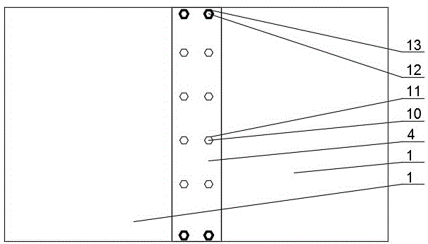
Fig. 1 is a schematic top view of the connecting cover slot covering the connecting bottom slot of the present invention;
fig. 2 is a schematic top view of the connecting cover slot of the present invention when opened;
fig. 3 is a schematic sectional structure of the present invention;
fig. 4 is a schematic sectional view of the connecting bottom groove and the connecting cover groove of the present invention.
In the figure: 1. a decorative plate body; 2. a connecting plate; 3. connecting the bottom groove; 4. a connecting cover groove; 5. connecting the jacks; 6. connecting the slots; 7. connecting the inserted link; 8. fixing the clamping groove; 9. fixing the clamping plate; 10. a connecting screw; 11. a first accommodating recess; 12. a set screw; 13. a second receiving recess.
Detailed Description
For a better understanding of the present invention, the contents of the present invention will be further clarified below by referring to examples, but the present invention is not limited to the following examples. In the following description, numerous specific details are set forth in order to provide a more thorough understanding of the present invention. It will be apparent, however, to one skilled in the art, that the present invention may be practiced without one or more of these specific details.
As shown in fig. 1 to 4, a sectional type building decorative panel, including decorative board body 1, the setting is at connecting plate 2 of 1 four sides of decorative board body, a connection kerve 3 that is used for carrying out the joint to two adjacent connecting plate 2's of adjacent decorative board body 1 lower extreme fixed and can with the bottom parallel and level of decorative board body 1, a connection cover groove 4 that is used for carrying out the joint to two adjacent connecting plate 2's of adjacent decorative board body 1 upper end fixed and can with the top parallel and level of decorative board body 1, jack 5 sets up on connecting plate 2, set up on connecting kerve 3 and with the corresponding connection slot 6 of jack 5, set up on connecting cover groove 4's middle part diapire and can pass jack 5 and with the connection slot 6 looks joint be connected inserted bar 7, set up at the fixed card board 9 of connecting the fixed card groove 8 of 3 sides of bottom groove and setting at the side of connecting cover groove 4 and with the adaptation of fixed card groove 8.
And a connecting screw 10 which passes through the connecting cover groove 4 and the connecting inserted rod 7 and is connected with the connecting inserted groove 6.
The top of the connecting cover groove 4 is provided with a first accommodating groove 11 matched with the upper end of the connecting screw 10.
And the fixing device also comprises a fixing screw 12 which passes through the connecting cover groove 4 and the fixing clamping plate 9 and is connected with the fixing clamping groove 8.
The top of the connecting cover groove 4 is provided with a second accommodating groove 13 matched with the upper end of the fixing screw 12.
It is specific, only need make the lower extreme of two adjacent connecting plates earlier fixed with the connection kerve joint, make the connection lid groove fixed to the upper end joint of two adjacent connecting plates afterwards, the connection lid groove is when fixed to the upper end joint of two adjacent connecting plates, it can pass connect the inserted bar and be connected with connect slot, fixed cardboard can be together fixed with the fixed slot joint, thereby realize the fixed connection to two adjacent connecting plates, again according to same method, with the fixed together of three remaining connecting plates of a decorative board body and rather than adjacent connecting plate, alright realize a decorative board body and with the fixed connection of four adjacent connecting plates, and then realize assembling to a plurality of decorative board bodies.
Because the bottom of connecting the kerve still with the bottom parallel and level of decorative board body, the top of connecting the lid groove still with the top parallel and level of decorative board body, so can avoid assembling the bottom of the decorative board of completion and can't closely paste with the wall and be in the same place, can avoid assembling the decorative board top of completion and can't closely paste with the bottom of other devices and be in the same place.
The connecting part of the connecting inserted rod and the connecting slot can be fixed through the connecting screw, and the connecting part of the fixing clamping plate and the fixing clamping slot can be fixed through the specified screw, so that the firmness of the decorative plate is improved, and the service life of the decorative plate is prolonged; through the first recess that holds, can make the top of connecting screw can not be outstanding to the top that is higher than the surface of decorative board body, through the second recess that holds, can make the top of set screw can not be outstanding to the top that is higher than the surface of decorative board body.
Finally, the above embodiments are only used for illustrating the technical solutions of the present invention and not for limiting, and other modifications or equivalent replacements made by the technical solutions of the present invention by those of ordinary skill in the art should be covered within the scope of the claims of the present invention as long as they do not depart from the spirit and scope of the technical solutions of the present invention.