Crane
Technical Field
The utility model relates to a lifting device technical field especially relates to a line hangs.
Background
The crane is a multi-action crane capable of lifting and carrying heavy objects in a certain range. The existing traveling crane in the current market lifts materials through a lifting device in the first step, moves on a cross beam along the length direction of the cross beam through a traveling device in the second step and moves in the vertical direction of the traveling crane relative to the length direction of the cross beam, carries the materials to the position above a material placing point, and reduces the height of the materials to the material placing point through the lifting device in the third step. Two operation modes of the ground and the control cabin are provided.
When the heavy object is hung, the heavy object is very heavy, the lifting hook and the lifting wheel are added, if workers do not pay attention to timely stopping the lifting, the lifting wheel can collide with the lifting device body, great damage can be caused to machinery, and the personal safety of the workers can be threatened.
SUMMERY OF THE UTILITY MODEL
The utility model aims at solving the defects existing in the prior art and providing a crane.
In order to achieve the above purpose, the utility model adopts the following technical scheme:
the utility model provides a line hangs, includes the crossbeam, the bottom of crossbeam is equipped with the spout, the inside of spout is rotated and is connected with the threaded rod, the outer fringe of threaded rod has the nut in the inside threaded connection of spout, the lower extreme symmetry of nut is equipped with two bracing pieces, two the inside of bracing piece is rotated jointly and is connected with the hanging wheel, the outer fringe coiling of hanging wheel has the haulage rope, the one end of haulage rope is equipped with the lifting hook, the inside of crossbeam still is equipped with the actuating mechanism who is used for driving the lifting hook and removes.
Preferably, actuating mechanism is including setting up in the motor of crossbeam upper end one side, the terminal fixedly connected with pivot of output shaft of motor, inside one side of crossbeam is equipped with the device groove, the lower extreme of pivot runs through the upper surface of crossbeam and extends to the inside in device groove, the outer fringe of pivot is in the inside fixedly connected with worm cover in the device groove, one end of threaded rod runs through one side of spout and extends to the inside in device groove, the one end of threaded rod is in the inside fixedly connected with worm wheel in the device groove, the worm wheel meshes with the worm cover.
Preferably, a rope winder is arranged below the cross beam, and the other end of the traction rope is wound inside the rope winder.
Preferably, two ends of the cross beam are respectively provided with a bracket for keeping the cross beam stable.
Preferably, a round rod is arranged inside the lifting hook, and one end of the traction rope is tied to the outer edge of the round rod.
Preferably, the edge of the hanging wheel is also provided with an annular groove matched with the traction rope to rotate.
The utility model has the advantages that:
1. the motor is arranged to drive the rotating shaft to rotate, then the worm sleeve drives the worm wheel to rotate, and then the threaded rod drives the hanging wheel and the hanging hook below the nut to move, so that the object is moved to a proper position;
2. the traction rope is tensioned or released by the rope winder, so that the hoisted object can be driven to ascend or descend, and the object is hoisted to a proper height.
Drawings
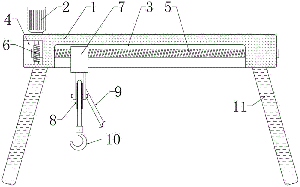
Fig. 1 is a schematic structural view of a traveling crane according to the present invention;
fig. 2 is a side view of a traveling crane according to the present invention.
In the figure: the device comprises a beam 1, a motor 2, a sliding chute 3, a device groove 4, a threaded rod 5, a worm wheel 6, a nut 7, a hanging wheel 8, a traction rope 9, a lifting hook 10, a support 11, a rotating shaft 12 and a worm sleeve 13.
Detailed Description
In order to make the objects, features and advantages of the present invention more obvious and understandable, the drawings in the embodiments of the present invention are combined below to clearly and completely describe the technical solutions in the embodiments of the present invention, and obviously, the embodiments described below are only some embodiments of the present invention, but not all embodiments. Based on the embodiments in the present invention, all other embodiments obtained by a person skilled in the art without creative efforts belong to the protection scope of the present invention.
The technical solution of the present invention is further explained by the following embodiments with reference to the accompanying drawings.
In the description of the present invention, it is to be understood that the terms "upper", "lower", "top", "bottom", "inner", "outer", and the like indicate orientations or positional relationships based on those shown in the drawings, and are only for convenience of description and simplicity of description, and do not indicate or imply that the device or element referred to must have a particular orientation, be constructed and operated in a particular orientation, and therefore should not be construed as limiting the present invention.
Referring to fig. 1-2, a traveling crane comprises a cross beam 1, a sliding chute 3 is arranged at the bottom of the cross beam 1, a threaded rod 5 is connected to the inside of the sliding chute 3 in a rotating mode, a nut 7 is connected to the outer edge of the threaded rod 5 in the sliding chute 3 in an internal threaded mode, two supporting rods are symmetrically arranged at the lower end of the nut 7, a hanging wheel 8 is connected to the two supporting rods in a rotating mode, a traction rope 9 is wound on the outer edge of the hanging wheel 8, a circular groove matched with the traction rope 9 to rotate is formed in the edge of the hanging wheel 8, a lifting hook 10 is arranged at one end of the traction rope 9, and a driving mechanism used for driving the lifting hook 10 to move is further arranged inside the cross beam 1.
The utility model discloses in, actuating mechanism is including setting up in the motor 2 of 1 upper end one side of crossbeam, the terminal fixedly connected with pivot 12 of output shaft of motor 2, inside one side of crossbeam 1 is equipped with device groove 4, the lower extreme of pivot 12 runs through the upper surface of crossbeam 1 and extends to the inside of device groove 4, the outer fringe of pivot 12 is in the inside fixedly connected with worm cover 13 of device groove 4, one side that spout 3 was run through to the one end of threaded rod 5 and extends to the inside of device groove 4, the one end of threaded rod 5 is in the inside fixedly connected with worm wheel 6 of device groove 4, worm wheel 6 meshes with worm cover 13, can drive worm wheel 6 through worm cover 13 and rotate, rethread threaded rod 5 drives hanging wheel 8 and the lifting hook 10 removal of nut 7 below, move the object to suitable position.
It is specific, crossbeam 1's below is equipped with the ropewinder, the other end of haulage rope 9 is convoluteed in the inside of ropewinder, can take-up or relieve haulage rope 9 through the ropewinder, can drive the object of being hoisted and rise or descend, with object hoist and mount to suitable height, crossbeam 1's both ends are equipped with respectively and are used for keeping 1 stable support 11 of crossbeam, the support 11 of both sides all is the shape of falling V and sets up, can improve crossbeam 1's stability, the inside of lifting hook 10 is equipped with the round bar, the one end of haulage rope 9 is tied in the outer fringe of round bar.
The utility model discloses during the use, earlier fix support 11 and crossbeam 1, then hoist the object through lifting hook 10, starter motor 2 and ropewinder afterwards, it rotates to drive pivot 12 through motor 2, then drive worm wheel 6 through worm cover 13 and rotate, 5 hanging wheel 8 and the lifting hook 10 that drive nut 7 below of rethread threaded rod move, move the object to suitable position, the ropewinder strains or releases haulage rope 9, can drive the object of being hoisted and rise or descend, hoist the object to suitable height.
The above embodiments are only used to illustrate the technical solution of the present invention, and not to limit the same; although the present invention has been described in detail with reference to the foregoing embodiments, it should be understood by those skilled in the art that: the technical solutions described in the foregoing embodiments may still be modified, or some technical features may be equivalently replaced; such modifications and substitutions do not depart from the spirit and scope of the present invention in its corresponding aspects.