Digital media art design interaction device capable of enhancing interestingness
Technical Field
The utility model relates to an art design technical field specifically is a can strengthen interesting digital media art design interactive installation.
Background
The art design is an independent art subject, and the art design is a term and mainly comprises: the environment design professional direction, the plane design professional direction, the visual transmission professional direction, the product design professional direction, and the like. The artistic design is to apply the aesthetic feeling of artistic form to the design closely related to daily life, so that the artistic design not only has aesthetic function, but also has practical function.
For example, patent No. CN210515727U discloses an interactive device for animation design teaching, which comprises a platform, wherein the left side of the upper end of the platform is provided with a computer, the lower end of the computer is provided with a first wireless module, the right side of the upper end of the platform is provided with a display screen, the left side of the platform is provided with a desk, the upper end of the desk is connected with a first fixed cover, the upper end of the desk is provided with a controller matched with the desk in position, the upper end of the controller is provided with buttons at equal intervals, the upper ends of the buttons penetrate through the first fixed cover and extend to the upper part of the first fixed cover, the upper end of the inner cavity of the first fixed cover is provided with a second wireless module, the interactive device has simple structural design and strong practicability, is convenient for teaching use, is convenient for effectively increasing the interactive opportunity between teachers and students, is convenient for effectively improving the learning effect of the students, and increases the teaching quality, and the teaching equipment is effectively protected.
Current interactive installation can set up the seat usually and supply to sit by in the student when using, but the seat is comparatively rigid fixed usually, can't reduce the regulation of height according to student's height and custom, makes the student feel uncomfortable easily to lead to the interactive effect to reduce, and current interactive installation interactive mode is comparatively single, and the interactive effect is comparatively general, unable better cultivation cooperation tacit degree between the student.
SUMMERY OF THE UTILITY MODEL
An object of the utility model is to provide a can strengthen interesting digital media art design interactive installation to solve the current interactive installation interactive mode that provides in the above-mentioned background comparatively single, interactive effect is comparatively general, the unable problem of the cooperation tacit degree of cultivateing between the student better.
In order to achieve the above object, the utility model provides a following technical scheme: a digital media art design interaction device capable of enhancing interestingness comprises a substrate; the substrate includes: the two side plates are respectively arranged on the left side and the right side of the base plate; the vertical rod is arranged in the middle of the top of the substrate; the top end of the vertical rod is rotatably provided with a table plate, two vertical grooves are formed in three-sixteenth length sections of the vertical rod, a sliding rod is slidably arranged in each of the two vertical grooves, and two L-shaped plates are arranged on five-sixteenth length sections of the vertical rod; the outer ends of the two side plates are respectively provided with a square plate, the tops of the two square plates are respectively provided with an adjusting rod, the middle of the top of each side plate is provided with a seat plate through a spring, the inner sides of the tops of the two side plates are respectively provided with an L-shaped stay bar, and the outer ends of the two L-shaped stay bars are respectively rotatably provided with a driving gear; both sides all are provided with a riser around the base plate, and all rotate on the riser of two and install a bull stick, and the outer end of these two bull sticks all is provided with a vice bevel gear.
Preferably, the seat plate includes: the two cushions are respectively arranged at the bottoms of the inner sides of the two seat plates, and the two seat plates are of L-shaped structures; the two vertical sliding strips are respectively arranged in the middle of the outer sides of the two seat plates and are respectively meshed with the two driving gears.
Preferably, the driving gear includes: the two transverse rollers are respectively arranged in the middle of the outer sides of the two driving gears; two main bevel gears are respectively arranged at the outer ends of the two transverse rollers, and the two main bevel gears are meshed with the auxiliary bevel gear at the outer end of the rotating rod.
Preferably, the L-shaped plate includes: the two sliding chutes are respectively arranged on the inner side walls of the two L-shaped plates; the two sliding columns are respectively and slidably arranged in the two sliding grooves; the two pedals are respectively arranged at the bottoms of the inner sides of the two L-shaped plates through springs, and the outer ends of the two pedals are connected with the inner end of one sliding column; the connecting rod, two connecting rods all set up in the top outside of a department footboard, and the top of two connecting rods all is connected with a slide bar.
Preferably, the table comprises: the bottom ring is of a circular ring structure and is arranged at the bottom of the table plate; the two jacks are symmetrically arranged at the bottom of the bottom ring; the two flat plate brackets are of inclined structures and are symmetrically arranged at the top of the table board.
Preferably, the slide bar comprises: the two loading discs are of disc-shaped structures and are arranged at the outer ends of the sliding rods; and the two insertion rods are respectively arranged in the middle of the tops of the two carrying discs.
Preferably, the adjusting lever includes: the two rows of fixing holes are arranged on the outer side of one adjusting rod at equal intervals from top to bottom; the two sleeves are respectively sleeved and slidably arranged on the two adjusting rods, and the inner sides of the two sleeves are respectively connected with the outer side walls of the two seat plates.
Preferably, the adjusting lever further comprises: the two fixing rods are of T-shaped structures and are respectively installed in the middle of the outer sides of the two sleeves in a sliding and inserting mode; the two circular baffle discs are respectively arranged on the middle sections of the two fixed rods, and a spring is arranged between the inner sides of the two circular baffle discs and the outer sides of the two sleeves.
Compared with the prior art, the beneficial effects of the utility model are that:
1. the utility model discloses be provided with the footboard, when two students want to rotate the table and exchange the artistic design achievement of vwatching the other side, need trample two footboards downwards simultaneously through two people, make it drive two connecting rods and descend, thereby make two connecting rods drag two slide bars and two inserted bars downwards, make it break away from with two jacks, make the table can rotate, and then need two students to cooperate to trample the footboard jointly and just can make the table can rotate, realize the cultivation to two student's tacit degree, the interactive interest of this device has also been strengthened simultaneously.
2. The utility model discloses be provided with vertical draw runner, when the student that is located one side needs to adjust the height of seat, need rotate the bull stick that corresponds through the student that is located the opposite side, make its drive gear that drives the correspondence under the cooperation of main bevel gear and vice bevel gear rotate, make drive gear drive vertical draw runner and the seat that corresponds rise, thereby make the seat can carry out the regulation of height according to student's custom and height, make student's interactive experience more comfortable, and the height of adjusting the seat needs the completion that another student's help could be convenient, and then cultivate student's mutual help and mutual help spirit, make possess stronger reunion nature between the student.
Drawings
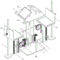
FIG. 1 is a schematic structural view of the present invention;
FIG. 2 is a schematic bottom structure of the present invention;
FIG. 3 is a schematic view of the structure of the table plate and the bottom ring of the present invention;
FIG. 4 is a schematic view of the adjusting lever and the seat plate of the present invention;
FIG. 5 is a schematic view of the structure of the L-shaped plate and the pedal of the present invention;
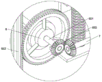
fig. 6 is a schematic diagram of a magnified portion of fig. 1 according to the present invention;
in the figure: 1. a substrate; 101. a side plate; 102. a vertical rod; 2. a table plate; 201. a bottom ring; 202. a jack; 203. a flat plate carrier; 3. a slide bar; 301. a carrying tray; 302. inserting a rod; 4. adjusting a rod; 401. a fixing hole; 402. a sleeve; 403. fixing the rod; 404. a circular baffle disc; 5. a seat plate; 501. a cushion; 502. a vertical slide bar; 6. a drive gear; 601. a transverse roller; 602. a main bevel gear; 7. a rotating rod; 8. an L-shaped plate; 801. a chute; 802. a traveler; 803. a pedal; 804. a connecting rod.
Detailed Description
The technical solutions in the embodiments of the present invention will be described clearly and completely with reference to the accompanying drawings in the embodiments of the present invention, and it is obvious that the described embodiments are only some embodiments of the present invention, not all embodiments.
Referring to fig. 1 to 6, the present invention provides an embodiment: a digital media art design interaction device capable of enhancing interestingness comprises a substrate 1; the substrate 1 includes: two side plates 101, wherein the two side plates 101 are respectively arranged at the left side and the right side of the substrate 1; a vertical rod 102, the vertical rod 102 is arranged in the middle of the top of the substrate 1; the top end of the vertical rod 102 is rotatably provided with a table plate 2, three sixths of the length of the vertical rod 102 is provided with two vertical grooves, the two vertical grooves are internally provided with a sliding rod 3 in a sliding way, and five sixths of the length of the vertical rod 102 is provided with two L-shaped plates 8; the outer ends of the two side plates 101 are respectively provided with a square plate, the tops of the two square plates are respectively provided with an adjusting rod 4, the middle of the tops of the two side plates 101 is respectively provided with a seat plate 5 through a spring, the inner sides of the tops of the two side plates 101 are respectively provided with an L-shaped support rod, and the outer ends of the two L-shaped support rods are respectively rotatably provided with a driving gear 6; the adjusting lever 4 further comprises: two fixing rods 403 are of a T-shaped structure, and the two fixing rods 403 are respectively slidably inserted into the middle of the outer sides of the two sleeves 402; two circular blocking discs 404 are respectively arranged on the middle sections of the two fixing rods 403, and a spring is arranged between the inner sides of the two circular blocking discs 404 and the outer sides of the two sleeves 402; both sides all are provided with a riser around the base plate 1, and all rotate on the riser of two and install a bull stick 7, and the outer end of these two bull sticks 7 all is provided with a vice bevel gear.
Further, the table 2 includes: the bottom ring 201, the bottom ring 201 is a circular structure, and the bottom ring 201 is arranged at the bottom of the table plate 2; two jacks 202, wherein the two jacks 202 are symmetrically arranged at the bottom of the bottom ring 201; the two flat plate brackets 203 are of an inclined structure, the two flat plate brackets 203 are symmetrically arranged at the top of the desk plate 2, the two flat plate brackets 203 can fix the tablet personal computer for art design, and the desk plate 2 is rotated to drive the two tablet personal computers to rotate, so that two students can interchange and view the art design results of the other students.
Further, the slide bar 3 includes: the two loading discs 301 are of disc-shaped structures, and the two loading discs 301 are arranged at the outer ends of the sliding rods 3; the two insertion rods 302 are respectively arranged in the middle of the tops of the two carrying trays 301, and the two insertion rods 302 are inserted into the two insertion holes 202, so that the bottom ring 201, the desk board 2 and the two tablet computers are fixed.
Further, the adjusting lever 4 includes: the two rows of fixing holes 401 are arranged on the outer side of the adjusting rod 4 from top to bottom at equal intervals; the sleeve 402, two sleeve 402 overlap the cunning respectively and install on two regulation poles 4, and the inboard of two sleeve 402 is connected with the lateral wall of two seat boards 5 respectively, when two seat boards 5 follow two sleeve 402 and upwards move to a certain position along two regulation poles 4, pull two dead levers 403 to the inboard through the spring, make it insert respectively in two suitable fixed orificess 401, thereby it is fixed to two sleeve 402 and two seat boards 5, make two seat boards 5 keep adjusting the suitable height after accomplishing.
Further, the seat plate 5 includes: the two seat cushions 501 are respectively arranged at the bottoms of the inner sides of the two seat plates 5, and the two seat plates 5 are in L-shaped structures; vertical draw runner 502, two vertical draw runners 502 set up respectively in the middle of the outside of two seats 5, and two vertical draw runners 502 mesh with two drive gear 6 respectively, when the seat 5 of one side needs height-adjusting, rotate corresponding bull stick 7 through the student that is located the opposite side, make it drive corresponding drive gear 6 and rotate under the cooperation of main bevel gear 602 and vice bevel gear, make drive gear 6 drive corresponding vertical draw runner 502 and seat 5 rise to adjust seat 5.
Further, the drive gear 6 includes: two horizontal rollers 601, two horizontal rollers 601 are respectively arranged at the middle of the outer sides of two driving gears 6; the main bevel gears 602 and the two main bevel gears 602 are respectively arranged at the outer ends of the two transverse rollers 601, the two main bevel gears 602 are respectively meshed with the auxiliary bevel gear at the outer end of the rotating rod 7, and the two driving gears 6 are rotated to drive the two vertical sliding strips 502 to ascend, so that the two seat plates 5 move upwards along with the two vertical sliding strips 502, and the height adjustment effect of the two seat plates 5 is achieved.
Further, the L-shaped plate 8 includes: the two sliding chutes 801 are respectively arranged on the inner side walls of the two L-shaped plates 8; the sliding columns 802, the two sliding columns 802 are respectively installed inside the two sliding grooves 801 in a sliding manner; two pedals 803, wherein the two pedals 803 are respectively arranged at the bottoms of the inner sides of the two L-shaped plates 8 through springs, and the outer ends of the two pedals 803 are connected with the inner end of one sliding column 802; the connecting rod 804 and the two connecting rods 804 are both disposed outside the top of one pedal 803, and the top ends of the two connecting rods 804 are both connected to one sliding rod 3, and the two pedals 803 are simultaneously stepped down to drive the two connecting rods 804 to descend, so that the two connecting rods 804 pull the two sliding rods 3 and the two insertion rods 302 downwards to separate from the two insertion holes 202, and the table 2 can rotate.
The working principle is as follows: when the multifunctional chair is used, firstly, the tablet personal computers for design are respectively fixed on two tablet brackets 203, then two students are respectively seated on two seat plates 5, so that the two students use the tablet personal computers for artistic design, when one of the students needs to adjust the height of the seat plate 5, the student pulls out the corresponding fixing rod 403 from the corresponding fixing hole 401, then the student on the other side rotates the corresponding rotating rod 7, so that the student drives the corresponding driving gear 6 to rotate under the matching of the main bevel gear 602 and the auxiliary bevel gear, so that the driving gear 6 drives the corresponding vertical sliding strip 502 and the seat plate 5 to ascend, so that the seat plate 5 can adjust the height according to the habits and heights of the students, when the seat plate 5 ascends to a certain position, the student does not pull the corresponding fixing rod 403 any more, so that the student can be inserted into the proper fixing hole 401 again under the action of the spring, thereby sleeve 402 and seat 5 are fixed, make seat 5 keep adjusting the suitable height after accomplishing, and after two students design, through two people trample two footboard 803 simultaneously downwards, make it drive two connecting rods 804 and descend, thereby make two connecting rods 804 drag two slide bars 3 and two inserted bar 302 downwards, make it break away from with two jacks 202, make table 2 can rotate, through rotating table 2 at last, make it drive two panel computers rotatory, make two students can interchangeable view the artistic design achievement of other side.
It is obvious to a person skilled in the art that the invention is not restricted to details of the above-described exemplary embodiments, but that it can be implemented in other specific forms without departing from the spirit or essential characteristics of the invention. The present embodiments are therefore to be considered in all respects as illustrative and not restrictive, the scope of the invention being indicated by the appended claims rather than by the foregoing description, and all changes which come within the meaning and range of equivalency of the claims are therefore intended to be embraced therein. Any reference sign in a claim should not be construed as limiting the claim concerned.