SUMMERY OF THE UTILITY MODEL
In order to facilitate clearing up the waste material, this application provides a pavement material strength test appearance.
The application provides a pavement material strength test appearance adopts following technical scheme:
a pavement material strength tester comprises a base, a bearing plate arranged on the base, a scrap cleaning device, a pressure applying device arranged above the bearing plate and a pressure sensor arranged on the pressure applying device; the scrap cleaning device comprises a bottom frame, a surrounding groove, a lifting cylinder and a rotating mechanism, wherein the bottom frame is arranged on the base around the bearing plate, a plurality of sliding blocks are arranged on the side wall of the surrounding groove along the circumferential direction, the bottom frame is provided with a sliding groove for the sliding blocks to slide along the vertical direction, the lifting cylinder is arranged on the bottom wall of an inner cavity of the bottom frame and is provided with a plurality of sliding blocks corresponding to the sliding blocks, and a piston rod of the lifting cylinder is arranged along the vertical direction and is connected with the sliding blocks; the rotating mechanism is arranged between the bearing plate and the base and can drive the bearing plate to rotate.
By adopting the technical scheme, when the physical properties of the pavement material are tested, the mobile material is placed on the bearing plate, and the lifting cylinder is adjusted to be opened, so that the piston rod of the lifting cylinder drives the enclosing groove to ascend along the sliding groove through the sliding block until the top wall of the enclosing groove is higher than the material; adjusting a pressure device to apply pressure to the material until the material is crushed, and reading the material strength reading of the material on the pressure sensor; the crushed materials fall into the bottom frame, the splashed materials are splashed on the inner wall of the surrounding groove and fall into the bottom frame again along the inner wall of the surrounding groove, the adjusting and rotating mechanism is started to enable the bearing plate to rotate, the waste materials on the bearing plate are thrown out of the bearing plate and fall into the bottom frame, and the waste materials are cleaned; the bottom frame, the surrounding groove and the lifting cylinder are arranged, the periphery of the material is surrounded and protected through the surrounding groove before the material is pressurized, broken waste scraps can fall into the bottom frame conveniently, splashed waste materials are blocked, the situation that the waste materials are splashed out to cause damage to operators is avoided, and safety is improved; the slewing mechanism who sets up can be through the rotation of accepting the board will accept the sweeps on the board and throw away, clears up accepting the board, is convenient for to the clearance and the collection of material sweeps, is convenient for test next material.
Optionally, the pressing device includes a pressing plate, a hydraulic cylinder, a fixing plate and four supporting columns, the fixing plate is arranged above the bearing plate in parallel, the four supporting columns are uniformly arranged around the bottom frame, and two ends of each supporting column are respectively arranged on the fixing plate and the base along the vertical direction; the hydraulic cylinder is arranged on one side of the fixing plate, which is far away from the bearing plate, and a piston rod of the hydraulic cylinder penetrates through the fixing plate and is connected with the force application plate.
By adopting the technical scheme, the arranged force application plate, the hydraulic cylinder, the fixed plate and the support column control the force application plate to ascend and descend through the hydraulic cylinder, so that the material on the bearing plate is pressed, and the operation is convenient; the hydraulic cylinder is supported through the fixing plate and the supporting columns, and force application of the hydraulic cylinder is facilitated.
Optionally, the sweeps cleaning device still includes the fan, the fan sets up the underframe lateral wall, the air intake has been seted up to the underframe lateral wall, the air intake orientation accept the board setting.
Through adopting above-mentioned technical scheme, the fan of setting can will accept the dust on the board and blow down and collect in falling into the underframe along enclosing the groove, is convenient for clear up the dust waste material of less particle diameter, improves the clearance effect of waste material.
Optionally, the rotating mechanism includes a supporting block, a rotating motor and a rotating shaft, an output shaft of the rotating motor is arranged on the base along a vertical direction, the supporting block is arranged on the base above the rotating motor, the receiving plate is arranged above the supporting block, one end of the rotating shaft is arranged on the bottom wall of the receiving plate, the other end of the rotating shaft penetrates through the supporting block and is rotatably connected with the supporting block, and the rotating shaft penetrates through one end of the supporting block and is coaxially connected with the output shaft of the rotating motor.
Through adopting above-mentioned technical scheme, the supporting shoe that sets up, rotate motor and pivot are supported accepting the board through the supporting shoe, are convenient for exert pressure to the material of accepting on the board, realize accepting the rotation of board through rotating motor and pivot.
Optionally, the bottom wall of the bearing plate is provided with a clamping strip, and the top wall of the supporting block is provided with a clamping groove for clamping the clamping strip; the rotating shaft is connected with the supporting block in a sliding mode, a guide piece capable of enabling the rotating motor to move in the vertical direction is arranged at one end, close to the base, of the rotating motor, and the guide piece enables the rotating motor to move in the direction close to the supporting block.
By adopting the technical scheme, the arranged clamping strip can avoid the influence on the measurement of the pressure sensor caused by the rotation of the bearing plate when the material is pressurized; the guide piece that sets up can make the card strip keep away from the draw-in groove when the clearance waste material, realizes accepting the rotation of board.
Optionally, the guide part includes at least a pair of guide bolt and spring, guide bolt passes rotate the motor and penetrate base and base threaded connection, the spring both ends set firmly respectively rotate on motor and the base, and can make it drives to rotate the motor the draw-in groove tends to keep away from.
Through adopting above-mentioned technical scheme, the deflector bolt and the spring that set up when biasing device is exerted pressure to the material, cushion accepting the board through the spring, when clearing up the waste material simultaneously, can make the card strip automatic keep away from the draw-in groove, guarantee the location of rotating the motor through deflector bolt, avoid rotating the motor and take place the biography certainly, and then guarantee to accept the rotation of board.
Optionally, it is provided with four sets of evenly distributed's setting element and drive four sets of on accepting the board to accept on the board the synchronous pivoted driving piece of setting element, the setting element includes bull stick, commentaries on classics board, clamp plate and torsional spring, the commentaries on classics board passes through the bull stick rotates to be connected accept on the board, the clamp plate articulates the commentaries on classics board is close to and accepts board center one side, just the articulated shaft of clamp plate sets up along vertical direction, the torsional spring sets up just can make on the articulated shaft of clamp plate the clamp plate tends to keep away from the commentaries on classics board.
Through adopting above-mentioned technical scheme, bull stick, commentaries on classics board, clamp plate and the torsional spring of setting can rotate through driving piece drive bull stick, and then makes the commentaries on classics board drive clamp plate rotate and support and press on the material to make the commentaries on classics board support through the torsional spring and push away the clamp plate, the clamp plate supports the location that pushes away the material and realize the material.
Optionally, the driving piece includes revolving cylinder, toothed chain and four rings, the coaxial setting of ring gear is in the bull stick passes accept the one end of board below, the toothed chain cover is established four on the ring gear and with the ring gear meshing sets up, revolving cylinder sets up accept on the board just revolving cylinder's piston rod and arbitrary the coaxial setting of bull stick.
Through adopting above-mentioned technical scheme, the synchronous rotation of four bull sticks is realized through the meshing of toothed chain and ring gear to the revolving cylinder, toothed chain and the ring gear that set up, and then makes revolving plate and clamp plate be close to the material with synchronous frequency to, the pressure applying of the biasing means of being convenient for.
In summary, the present application includes at least one of the following beneficial technical effects:
1. the bottom frame, the surrounding groove and the lifting cylinder are arranged, the periphery of the material is surrounded and protected through the surrounding groove before the material is pressurized, broken waste scraps can fall into the bottom frame conveniently, splashed waste materials are blocked, the situation that the waste materials are splashed out to cause damage to operators is avoided, and safety is improved; the rotating mechanism can throw the scraps on the bearing plate out through the rotation of the bearing plate, clean the bearing plate, facilitate the cleaning and collection of the scraps of the materials and facilitate the test of the next material;
2. the guide bolt and the spring are arranged, when the pressing device presses materials, the bearing plate is buffered through the spring, meanwhile, when waste materials are cleaned, the clamping strips can be automatically far away from the clamping grooves, the positioning of the rotating motor is guaranteed through the guide bolt, the rotating motor is prevented from being self-transmitted, and further the rotation of the bearing plate is guaranteed;
3. the rotating cylinder, the toothed chain and the toothed ring are arranged, synchronous rotation of the four rotating rods is achieved through meshing of the toothed chain and the toothed ring, and therefore the rotating plate and the pressing plate are close to materials with synchronous frequency, the materials are located on the bearing plate in the middle, and pressing of the pressing device is facilitated.
Detailed Description
The present application is described in further detail below with reference to figures 1-3.
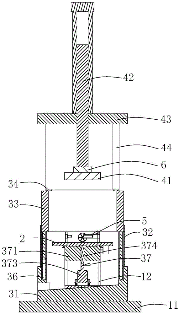
The embodiment of the application discloses pavement material strength tester. Referring to fig. 1 and 2, the pavement material strength tester comprises a base 1, a bearing plate 2, a scrap cleaning device 3, a pressing device 4, a positioning device 5 and a pressure sensor 6 arranged on the pressing device 4; the base 1 comprises a bottom plate 11 and a motor cover 12, the bottom plate 11 is fixed on the ground through expansion bolts, the motor cover 12 is welded at the center of the bottom plate 11, a bearing plate 2, a scrap cleaning device 3 and a pressure applying device 4 are all arranged on the bottom plate 11, a positioning device 5 is arranged on the bearing plate 2, and a pressure sensor 6 is arranged on the pressure applying device 4.
Referring to fig. 2 and 3, the scrap cleaning device 3 includes a material receiving frame 31, a bottom frame 32, a surrounding groove 33, a baffle ring 34, a fan 35, a lifting cylinder 36 and a rotating mechanism 37, the material receiving frame 31 is welded at the center of the bottom plate 11, the bottom wall is obliquely arranged, and a material outlet 311 is formed in the side wall of the bottom wall of the material receiving frame 31 close to the lower side; the bottom frame 32 and the surrounding groove 33 are both arranged in a cylindrical barrel shape, and the bottom frame 32 is vertically welded on the inner wall of the material receiving frame 31 around the center of the material receiving frame 31 and is communicated with the material receiving frame 31. Enclose groove 33 and evenly weld on the lateral wall along circumference and have four slider 38, the gliding spout of confession slider 38 along vertical direction is seted up to underframe 32 inner wall, keeps off ring 34 and welds and enclose groove 33 along axial roof, and keeps off ring 34's internal diameter and is not less than and accept the board 2 external diameter. Four lifting cylinders 36 are arranged and fixed in the sliding grooves through bolts in the same direction as the sliding grooves, and one end of a piston rod of each lifting cylinder 36 is welded to the bottom wall of the sliding block 38 along the vertical direction; the lateral wall of the bottom frame 32 close to the top wall is provided with an air inlet, the air inlet is arranged right opposite to the top wall of the bearing plate 2, and the fan 35 is fixed at the air outlet of the bottom frame 32 through a bolt.
Referring to fig. 2 and 3, the rotating mechanism 37 includes a supporting block 371, a clamping strip 372, a rotating motor 373, a rotating shaft 374 and a guiding member, the guiding member includes two pairs of guiding bolts 375 and a spring 376, the rotating motor 373 adopts a servo motor and is disposed in the motor cover 12 in the embodiment of the present application, the output end of the rotating motor 373 faces the receiving plate 2, the guiding bolt 375 passes through the rotating motor 373 and passes through the collecting frame bottom wall to be in threaded connection with the bottom plate 11, the spring 376 is sleeved between the rotating motor 373 and the bottom frame 32 bottom wall at the guiding bolt 375, and two ends of the spring 376 are respectively welded on the rotating motor 373 and the bottom frame 32 bottom wall, and the spring 376 can enable the rotating motor 373 to drive the clamping strip 372 to tend to be away from the clamping slot. Supporting shoe 371 welds on motor cover 12 roof, accepts board 2 and sets up on supporting shoe 371, and the welding of card strip 372 is accepted 2 diapalls of board, and the draw-in groove that supplies card strip 372 card to establish is seted up to supporting shoe 371 roof. One end of the rotating shaft 374 is coaxially welded on the bottom wall of the bearing plate 2, the other end of the rotating shaft 374 penetrates through the supporting block 371 and is in rotating and sliding connection with the supporting block 371, and one end of the rotating shaft 374 penetrating through the supporting block 371 extends into the motor cover 12 and is coaxially welded with an output shaft of the rotating motor 373.
Referring to fig. 1, the pressing device 4 includes a pressing plate 41, a hydraulic cylinder 42, a fixing plate 43 and four supporting columns 44, the fixing plate 43 is disposed above the bearing plate 2 in parallel, the four supporting columns 44 are respectively disposed on the bottom wall of the fixing plate 43 near four corners, and two ends of the supporting columns 44 are respectively welded to the fixing plate 43 and the base 1 along the vertical direction. The hydraulic cylinder 42 is fixed on one side of the fixing plate 43 far away from the bearing plate 2 through a bolt, and a piston rod of the hydraulic cylinder 42 penetrates through the fixing plate 43 and is welded on a pressure plate 53 arranged in parallel with the bearing plate 2; the pressure sensor 6 is mounted on the pressure plate 53.
Referring to fig. 2 and 3, the positioning device 5 includes positioning elements and driving elements, the positioning elements of four groups are uniformly distributed on the top wall of the bearing plate 2 close to the side wall, the positioning elements include a rotating rod 51, a rotating plate 52, a pressure plate 53 and a torsion spring 54, and the driving elements include a rotating cylinder 55, a toothed chain 56, four toothed rings 57 and four baffles 58; the rotating plate 52 is rotatably connected to the top wall of the bearing plate 2 through an axially vertical rotating rod 51, a toothed ring 57 is coaxially welded at one end of the rotating rod 51 penetrating through the lower part of the bearing plate 2, and a baffle plate 58 is coaxially welded at one side of the toothed ring 57 far away from the bearing plate 2; the toothed chain 56 is sleeved on the four toothed rings 57 and meshed with the toothed rings 57, the mounting plate is welded on the bottom wall of the bearing plate 2, the rotating cylinder 55 is fixed on the mounting plate through bolts, and a piston rod of the rotating cylinder 55 is coaxially welded on one side, far away from the toothed rings 57, of any baffle plate 58. The pressing plate 53 is hinged to one side of the rotating plate 52 close to the center of the bearing plate 2, a hinged shaft of the pressing plate 53 is arranged along the vertical direction, the torsion spring 54 is sleeved on the hinged shaft of the pressing plate 53, two ends of the torsion spring 54 are respectively welded on the pressing plate 53 and the rotating plate 52, and the torsion spring 54 can enable the pressing plate 53 to tend to be away from the rotating plate 52.
The implementation principle of the pavement material strength tester in the embodiment of the application is as follows: when testing the physical properties of pavement materials, remove the material and place on accepting board 2, adjust revolving cylinder 55 and start, make revolving cylinder 55's piston rod pass through baffle 58 and drive ring gear 57 and bull stick 51 and rotate, and then drive chain gear 56 and rotate with other three ring gear 57 of chain gear 56 meshing, thereby drive four bull sticks 51 synchronous rotation, bull stick 51 drives revolving plate 52 and moves to being close to the material direction, and then make revolving plate 52 drive clamp plate 53 rotate and support and press on the material, until clamp plate 53 tightly supports on the material under the torsional spring 54 effect, revolving plate 52 tightly supports on clamp plate 53, make the material location in the middle on accepting board 2. Adjusting the lifting cylinder 36 to start, so that a piston rod of the lifting cylinder 36 drives the enclosing groove 33 to ascend along the sliding groove through the sliding block 38 until the bottom wall of the enclosing groove 33 is higher than the air outlet; adjust pneumatic cylinder 42 and start, make pneumatic cylinder 42's piston rod drive application of force board 41 to being close to the material direction motion, application of force board 41 supports and presses the material and accepts board 2 to being close to supporting shoe 371 direction motion, establish in the draw-in groove until card strip 372 card, application of force board 41 continues to push down, until with the material crushing, and read out the material intensity reading of material on the pressure sensor 6, accomplish the strength test to the material, later adjust pneumatic cylinder 42, make application of force board 41 reset, accept board 2 and card strip 372 and keep away from the draw-in groove under the effect of spring 376.
When clearing up the waste material, the material of crushing falls in receiving material frame 31, the material that splashes spatters on enclosing groove 33 inner wall and falls into again along enclosing groove 33 inner wall and receive material frame 31 in, adjust and rotate motor 373 and start, the output shaft that rotates motor 373 drives through pivot 374 and accepts board 2 and rotates, throw away the waste material on accepting board 2 and accept board 2 and fall into receiving material frame 31 in, open fan 35 simultaneously, the less sweeps of particle diameter on accepting board 2 blows down in receiving material frame 31, waste material in receiving material frame 31 is discharged along discharge gate 311, the completion is to the clearance of waste material.
The above embodiments are preferred embodiments of the present application, and the protection scope of the present application is not limited by the above embodiments, so: all equivalent changes made according to the structure, shape and principle of the present application shall be covered by the protection scope of the present application.